 Open Access Article
Detection of magnetic field effects by confocal microscopy†
Victoire
Déjean
 a,
Marcin
Konowalczyk
 ab,
Jamie
Gravell
 a,
Matthew J.
Golesworthy
 a,
Catlin
Gunn
a,
Nils
Pompe
a,
Olivia
Foster Vander Elst
a,
Ke-Jie
Tan
c,
Mark
Oxborrow
a,
Catlin
Gunn
a,
Nils
Pompe
a,
Olivia
Foster Vander Elst
a,
Ke-Jie
Tan
c,
Mark
Oxborrow
 c,
Dirk G. A. L.
Aarts
b,
Stuart R.
Mackenzie
 b and
Christiane R.
Timmel
 *ad
*ad
aDepartment of Chemistry, University of Oxford, Inorganic Chemistry Laboratory, Oxford, OX1 3QR, UK. E-mail: christiane.timmel@chem.ox.ac.uk
bDepartment of Chemistry, University of Oxford, Physical and Theoretical Chemistry Laboratory, Oxford, OX1 3QZ, UK
cDepartment of Materials, Imperial College London, London, SW7 2AZ, UK
dCentre for Advanced Electron Spin Resonance (CAESR), Department of Chemistry, University of Oxford, Oxford, OX1 3QR, UK
First published on 22nd July 2020
Abstract
Certain pairs of paramagnetic species generated under conservation of total spin angular momentum are known to undergo magnetosensitive processes. Two prominent examples of systems exhibiting these so-called magnetic field effects (MFEs) are photogenerated radical pairs created from either singlet or triplet molecular precursors, and pairs of triplet states generated by singlet fission. Here, we showcase confocal microscopy as a powerful technique for the investigation of such phenomena. We first characterise the instrument by studying the field-sensitive chemistry of two systems in solution: radical pairs formed in a cryptochrome protein and the flavin mononucleotide/hen egg-white lysozyme model system. We then extend these studies to single crystals. Firstly, we report temporally and spatially resolved MFEs in flavin-doped lysozyme single crystals. Anisotropic magnetic field effects are then reported in tetracene single crystals. Finally, we discuss the future applications of confocal microscopy for the study of magnetosensitive processes with a particular focus on the cryptochrome-based chemical compass believed to lie at the heart of animal magnetoreception.
Introduction
Certain chemical reactions, namely those proceeding via radical pair intermediates, exhibit a surprising sensitivity to applied magnetic fields.1–3 Both time-dependent and static fields, independently or in combination, have been reported to affect the kinetics and/or yields of these reactions.4Most chemical reactions known to exhibit such field sensitivity involve pairs of radicals created in highly spin-correlated states under conservation of total spin angular momentum. As will be discussed in more detail below, application of weak magnetic fields affects the spin dynamics and consequently the reactivity of the pair. The field sensitivity of such radical pair processes finds application in a wide variety of scientific disciplines ranging from biology (e.g. in the study of the initial processes in photosynthesis), to physics and materials (e.g. in the field of organic electronics).5–7
The field sensitivity of spin-correlated radical pairs (RPs) has been proposed as central to the phenomenon of avian magnetoreception.8 Three developments have added particular weight to this hypothesis. Firstly, the blue light photoreceptor protein cryptochrome was discovered in the retinas of migratory birds.9,10 Secondly, the formation of field-sensitive RPs following blue light illumination was experimentally proven by both optical spectroscopy and electron paramagnetic resonance.11 Finally, a molecular triad system was recently shown to act as a chemical compass, sensing not only the strength but also the direction of a 100 μT magnetic field.12,13
The effect of magnetic fields is not restricted to chemical reactions proceeding via spin-correlated RPs (with individual spins s = 1/2). When species in states of higher multiplicity are created from their molecular precursors, also under conservation of total spin angular momentum, other magnetosensitive processes are known to occur. A prominent example regards the singlet fission process resulting in two spin correlated triplet states from a singlet molecular precursor. In analogy to radical pair reactions, the recombination of these triplet states has been shown to be sensitive to applied static magnetic fields.14
Most field effects, if arising from radical or triplet pairs, have been detected by optical spectroscopy. Absorption-based methods include transient absorption,12,15 cavity ring-down and cavity-enhanced absorption spectroscopies.16,17 These techniques allow the identification of ground and excited state species and the quantification of the magnetic field sensitivity of their respective concentrations. Transient absorption and ring-down spectroscopies furthermore facilitate a detailed kinetic analysis. Fluorescence techniques, on the other hand, exhibit superior sensitivity and find particular application in exploring systems of low optical quality (such as colloidal, inhomogeneous or otherwise strongly scattering samples). Most commonly, such studies have monitored the field effects via observation of the delayed fluorescence (most commonly via exciplex or p-type fluorescence).18,19 Recently, however, Evans et al. demonstrated that the magnetosensitivity of a radical pair generated by continuous photoexcitation may also be studied via the prompt fluorescence of the photosensitiser.20 The study focused on a flavin photosensitiser and a tryptophan electron donor, a system further investigated in subsequent work by Kattnig et al. using wide-field microscopy of bulk solutions.21 In this work, we exploit fluorescence microscopy further to study photosensitive and photosensitiser-doped single crystals. The results showcase confocal microscopy as a powerful technique for the characterisation of the spatiotemporal evolution of MFEs, not only in bulk solutions, but also in crystals. Owing to the ability of confocal imaging to block out-of-focus light and therefore image only a thin focal plane, the fluorescence emitted by the crystal can be discriminated from that emitted by the surrounding solution.
This article will commence with a short introduction into the physical origins of magnetic field effects on spin-correlated pairs of both radicals and triplets states. We then report microscopy-detected MFEs on a number of chemical systems exemplifying both mechanisms.
Pairs of radicals generated from a molecular precursor under conservation of total spin angular momentum are formed in highly spin-polarised states. This results in a pronounced magnetic field sensitivity of their spin dynamics and consequently the fate of the RP. Below we illustrate this mechanism on the examples of two flavin/tryptophan radical pairs (see chemical structures in Fig. 1). Firstly, the radical pair mechanism (RPM) and the origin of magnetic field effects are discussed with reference to cryptochrome before similarities and differences to a frequently employed cryptochrome model system are highlighted.
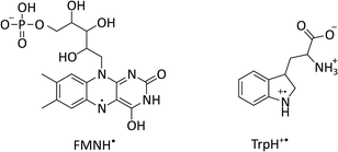 | ||
| Fig. 1 Chemical structures of flavin mononucleotide (FMN) in its semiquinone form (left) and a tryptophan radical (right) at pH 4.2.22–24 | ||
In cryptochromes, blue light photoexcitation of the non-covalently bound flavin adenine dinucleotide cofactor (FAD, which also contains an isoalloxazine moiety, but differs from FMN in the nature of the ribityl chain) is followed by rapid, intramolecular electron transfer along a chain of either three or four tryptophans, see Fig. 2a.12,28 The resulting radical pair, 1[FAD˙− TrpH˙+], also called RP1, is formed in an initial singlet state and typically lives for several microseconds. In the absence of strong interradical interactions, the singlet state is not an eigenstate of the spin Hamiltonian. Consequently, the radical pair undergoes coherent interconversion to a triplet state (and back, repeatedly), a process driven by the hyperfine couplings between electron and nuclear spins. This singlet–triplet interconversion is field-sensitive: if the applied field exceeds the effective hyperfine coupling in the pair (as is the case for all fields in this study), two of the triplet sublevels (namely the T+ and T− states) become energetically isolated from the S/T0 manifold. As a result, the efficiency of singlet–triplet interconversion is reduced.
 | ||
| Fig. 2 Photoschemes of the RP systems investigated in this work. (a) Blue light photoexcitation of the FAD cofactor in the cryptochrome protein from the plant Arabidopsis thaliana (AtCry1) is followed by rapid intramolecular electron transfer along a triad of tryptophans (see inset). The RP 1[FAD˙− TrpH˙+] is consequently formed in a singlet state and undergoes coherent, field-sensitive singlet–triplet interconversion. Only 1[FAD˙− TrpH˙+] may recombine to the ground state. However, protonation of the flavin anion and deprotonation of the tryptophan cation are non-spin-selective and lead to formation of RP2, a pair of radicals that has lost any spin correlation and is not field-sensitive. The prompt fluorescence of 1FAD* is monitored by confocal microscopy. Inset drawn from PDB entry 1U3D.25,26 (b) The cryptochrome model system used in this study comprises FMN as the electron acceptor and a Trp residue from HEWL as the electron donor (see inset). In contrast to cryptochromes, photoexcitation of the flavin is followed by intersystem crossing to 3FAD* before electron transfer from the Trp and protonation of the flavin result in the formation of 3[FMNH˙ TrpH˙+]. Again, recombination can only occur from the singlet pair whilst the RP partners can undergo diffusional separation and termination reactions spin-independently. Inset drawn from PDB entry 1DPX.26,27 | ||
In order to observe magnetic field effects on reaction yields and/or kinetics, singlet and triplet radical pairs must have different fates. Only singlet radical pairs may recombine to the ground state, triplet recombination being spin-forbidden. However, both singlet and triplet radical pairs can, usually via protonation or deprotonation of one or both of the radical partners, yield a further pair of radicals. Formation of this radical pair (referred to as RP2) from the initial spin-polarised radical pair (RP1) is not spin-selective. RP2 has lost any spin-correlation and no further singlet–triplet interconversion takes place. The field dependence of the RP dynamics, together with this difference in singlet and triplet pair fates, leads to field-sensitive recombination kinetics and concentrations of all species in the photoscheme. The presence of a large magnetic field decreases the RP2 concentration and consequently increases the ground state population. As a result, the flavin fluorescence in any steady-state illumination experiment increases in the presence of a large magnetic field.
The most frequently employed cryptochrome model system, consisting of flavin mononucleotide (FMN) and hen egg-white lysozyme (HEWL), follows similar photochemistry and field-sensitive radical pair kinetics but exhibits some crucial differences, see Fig. 2b. Photoexcitation of the flavin is followed by intersystem crossing to generate 3FMN. Subsequent intermolecular electron transfer from tryptophan residues Trp 62 or Trp 123 on HEWL to the flavin cofactor, and rapid protonation of the latter, create an initial triplet radical pair 3[FMNH˙ TrpH˙+].29,30 This triplet pair has no direct recombination path to the ground state but first has to undergo coherent triplet–singlet interconversion. As before, however, singlet and triplet RPs can undergo further spin-independent reactions such as reduction of TrpH˙+ or oxidation of FMNH˙, as discussed in detail by Kattnig et al.21 More importantly, the RP can also undergo spin-independent diffusive separation forming free radicals. As a result, the intramolecular radical pair in cryptochrome and the intermolecular radical pair in FMN/HEWL exhibit opposite trends in their field sensitivities.
Triplet exciton pairs
By analogy with the rates of bimolecular reactions involving pairs of radicals (pairs of spin-1/2 species), processes involving pairs of triplet excitons (spin-1 species), have also been shown to be field-sensitive.14,32 These triplet excitons are typically formed via a photoinitiated process termed singlet fission which occurs in molecular crystals, aggregates, conjugated polymers, and dimers of suitable organic chromophores.33The process commences with photoexcitation generating a chromophore in its first excited singlet state, see Fig. 3. This excitation energy, if approximately equal to or greater than twice that of a suitable triplet state, may then be shared with a neighbouring ground-state chromophore. As a result, and under conservation of total spin angular momentum, the formation of a spin-correlated triplet exciton pair (SCTEP) on neighbouring chromophores can ensue. Under the influence of the zero-field splitting (electron–electron dipolar interaction) of the two triplets, coherent interconversion between the singlet and quintet states, 1(3P3P) and 5(3P3P), ensues.33 This process is affected by both the magnitude and orientation of an applied magnetic field.
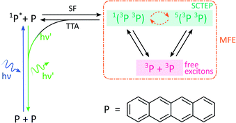 | ||
| Fig. 3 Photoscheme of the exciton pair system investigated in this work. Following blue light photoexcitation of a polyaromatic species, here tetracene (P), the singlet excited state can undergo singlet fission (SF) with a neighbouring ground state molecule. Zero field splitting and Zeeman interactions determine the extent of singlet–quintet mixing. Note that this discussion and the simulations conducted in this work neglect the effect of anisotropic g-values and the existence of two non-equivalent sites in the herringbone structure of tetracene single crystals. Both drive the system additionally into the 3(3P3P) state, but are of little relevance in the temperature regimes and fields considered here.31 Only 1(3P3P) may recombine by triplet–triplet annihilation (TTA), the result of which can be monitored by delayed fluorescence of 1P*. | ||
Furthermore, only excitonic pairs in an overall singlet state may recombine in a spin-selective process called triplet–triplet annihilation (the reverse of singlet fission). It yields a singlet ground and singlet excited state, the latter of which may undergo radiative decay to emit delayed fluorescence. Therefore, in close analogy to systems subject to the RPM, the delayed fluorescence in such singlet fission materials may depend on the strength of any applied magnetic fields (via the Zeeman interaction, as before). Importantly, the zero-field splitting interactions in the triplet excitons may render such field effects anisotropic.
Methods
Chemical systems
The following chemicals were purchased from Sigma-Aldrich and used without further purification: FMN (catalogue number F6750), HEWL (62971), sodium chloride (31434-M), acetic acid (A6283), TRIS (154563) and potassium ferricyanide (208019). HCl and glycerol were obtained from Fisher Scientific (catalogue numbers 10316380 and 10336040, respectively) and used without further purification.Lysozyme crystals were prepared by batch method. A protein solution (3.5 mM HEWL, 100 μM FMN) and a precipitant solution (1 M NaCl) were mixed in equal proportions. Both stock solutions were prepared in 0.1 M acetate buffer, pH![[thin space (1/6-em)]](https://www.rsc.org/images/entities/char_2009.gif) =
=![[thin space (1/6-em)]](https://www.rsc.org/images/entities/char_2009.gif) 4.2. 1 mL of the resulting solution was pipetted in a glass-bottom dish and stored in the dark at room temperature. Crystals appeared after one or two days. X-ray data showed that HEWL crystallised in the tetragonal space group P43212. When grown in the presence of FMN, HEWL crystals exhibited an increased unit cell volume (unit cell parameters are given in the ESI†), indicating that the crystal structure expanded to incorporate the dopant. No additional difference from the FMN-free crystals was observed, suggesting that FMN is not ordered within the crystal.
4.2. 1 mL of the resulting solution was pipetted in a glass-bottom dish and stored in the dark at room temperature. Crystals appeared after one or two days. X-ray data showed that HEWL crystallised in the tetragonal space group P43212. When grown in the presence of FMN, HEWL crystals exhibited an increased unit cell volume (unit cell parameters are given in the ESI†), indicating that the crystal structure expanded to incorporate the dopant. No additional difference from the FMN-free crystals was observed, suggesting that FMN is not ordered within the crystal.
AtCry1 was provided by Planet Biotechnology Inc., USA. The cryptochrome sample (∼75 μM) was studied in 50 mM Tris/HCl buffer at pH 7.0 with 100 mM NaCl, and approximately 30% glycerol v/v. Potassium ferricyanide (2 mM) was added to promote reoxidation of the flavin.
Tetracene crystals were grown using the “open” variant of the physical vapour transport (PVT) method.34,35 High-purity argon was used as the flow gas. The charge comprised tetracene crystals that had been purified through vapour sublimation. The starting material was >99.8% tetracene from Tokyo Chemical Industries.
Apparatus
The sample was excited continuously at 458![[thin space (1/6-em)]](https://www.rsc.org/images/entities/char_2009.gif) nm through a 63× oil-immersion objective using an inverted Zeiss confocal microscope (LSM 5 Exciter). The emitted fluorescence was recorded by a photomultiplier tube. A 475 nm long-pass filter prevented scattered light from the excitation beam reaching the detector. The imaging parameters used are detailed in the ESI.†
nm through a 63× oil-immersion objective using an inverted Zeiss confocal microscope (LSM 5 Exciter). The emitted fluorescence was recorded by a photomultiplier tube. A 475 nm long-pass filter prevented scattered light from the excitation beam reaching the detector. The imaging parameters used are detailed in the ESI.†
The magnetic field was generated by two orthogonal pairs of home-built solenoids wound around ferrite cores. To test the effect of magnetic fields on the sample fluorescence, only one pair of coils was used and the applied field was switched alternately between 0 and 16 mT (with a rise time of ∼70 ms) every few frames using a waveform generator (Rigol DG1022).
The effects of magnetic fields on the fluorescence intensity are displayed in two formats in this paper:
(i) Via the field-dependent fluorescence intensity, I, following the initiation of the experiment at time t = 0. Field-on (Ion) and field-off (Ioff) periods can usually be easily distinguished as step functions in the fluorescence decay curves.
(ii) Via percentage magnetic field effect, defined as:
 | (1) |
To test the response of the fluorescence of a tetracene crystal to the direction of an applied magnetic field, both pairs of coils were employed. In such experiments, the field's intensity was held constant at 16 mT but its direction was either parallel (B∥) or perpendicular (B⊥) to the crystallographic b-axis of the crystal.
With the exception of the cryptochrome studies, experiments were conducted at room temperature. To maximise MFEs in AtCry1 and minimise protein degradation, cryptochrome solutions were maintained at approximately 5 °C using a water-cooled sample holder.12
Fluorescence recovery after photobleaching (FRAP) was used to determine the degree of immobilisation of the flavin molecules within the crystal. This technique involves laser irradiation of a region of interest (ROI) at high power, resulting in significant photobleaching and a subsequent drop in the fluorescence intensity within that region. Following termination of the high power irradiation, fresh and bleached sample diffuse into and out of this region, respectively. As a result, a recovery of the fluorescence intensity is observed. The evolution of the temporal and spatial fluorescence profile following the bleaching event can then be used to estimate the diffusion coefficient and the extent of immobilisation of the fluorophore molecules.
Laser irradiation (458 nm, 70 μW power) was used to bleach a 40 × 40 × 5 μm3 region within a 101.8 μm wide frame for 5 s. The subsequent recovery of the fluorescence was monitored with the same laser at 0.9 μW. The analysis was conducted according to the method outlined by Aarts et al.36
Data analysis
The data were acquired as a time stack of frames. The pixels in the ROI of each frame were averaged together and their intensity analysed over the course of the experiment.To obtain spatially resolved %MFEs, multiple small ROIs were considered. In this work, it was found that a 4 × 4 pixel bin was sufficient to obtain enough superpixel bit depth to detect spatially resolved MFEs. The average intensity of each ROI was then sliced into up/down (u/d) segments in synchrony with the field steps. A number of data points were omitted at the edge of each segment to allow for minor uncertainties in timing as the laser scans through the whole frame. For each triplet of u–d–u and d–u–d segments, the outer segments were fitted with a quadratic function whose difference to the central segment results from a change in the magnitude or direction of the magnetic field. The %MFE could then be calculated using eqn (1). In many instances, the initial decay of the fluorescence intensity was too fast to resolve the MFE, and these initial segments were, therefore, discarded.
The average %MFE step over multiple off-on cycles were obtained by averaging over all pixels of the ROI and, once again, splitting them into u/d segments. In order to make the dynamics of the MFE within one step visible (like in Fig. 8), the fluorescence baseline needs to be subtracted. It is obtained from a smoothing interpolent through the centre points between each pair of u–d and d–u segments (see ESI† for details). The baseline-subtracted data is then shifted such that the average field-off segment is centred at 0, and divided by the baseline intensity to obtain the %MFE. The average %MFE step is either fitted with a square wave or a piecewise single exponential. Further information regarding these fitting functions is provided in the ESI.†
The analysis of FRAP data was conducted as follows. The intensity profiles along the x-axis at different times after bleaching were obtained by averaging over several pixels along the y-axis. The normalised intensity profiles can be described by an error function:37
 | (2) |
Results and discussion
Detection of magnetic field effects in solution
We will commence our discussions with the study of magnetic field effects on flavin-based radical pairs in solution. Similar investigations have previously been performed by Kattnig et al.,21 albeit using a wide-field fluorescence microscope and different data analysis protocols (see Experimental section and ESI†). The results outlined here will serve as an important reference point in the analysis of the crystal results discussed subsequently.![[thin space (1/6-em)]](https://www.rsc.org/images/entities/char_2009.gif) s period (i.e., 30
s period (i.e., 30![[thin space (1/6-em)]](https://www.rsc.org/images/entities/char_2009.gif) s “field-on”, 30 s “field-off”).
s “field-on”, 30 s “field-off”).
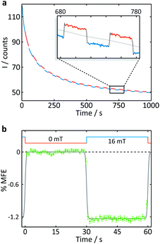 | ||
| Fig. 4 Measurement of an aqueous solution of 10 μM FMN and 1 mM HEWL by confocal microscopy. (a) Fluorescence intensity as a function of time after the onset of continuous illumination at 458 nm. An applied magnetic field is switched between 0 and 16 mT approximately every 30 s. Blue segments were recorded in the presence of a 16 mT field (“field-on”), red segments correspondingly in the absence of any applied field (“field-off”. (b) Average %MFE of 14 on-off steps (see ESI† for full data and analysis). A step function was fitted to the data to guide the eye. | ||
A number of features are apparent. Firstly, the fluorescence intensity exhibits a substantial decay over the course of the experiment (∼16 min). Although it can be fitted reasonably successfully by a biexponential decay as well as an additional constant offset (see ESI†), the contributions to the long-term evolution of the fluorescence intensity are numerous. Photodegradation of the flavin is certainly the main driving factor behind this decay, but this effect is strongly affected by diffusion, both of photodegradation products out of the illuminated region and of fresh FMN into the illuminated region (see discussion on crystals below). Additionally, the solutions are not de-oxygenated (in part for comparability with the cryptochrome experiments below where oxygen is crucial for reoxidation of the sample) so that triplet–triplet (3FMN–3O2) quenching and, therefore, oxygen diffusion into and out of the illuminated region also contribute. Finally, the illuminated system, even in the absence of any photodegradation, takes time to reach the steady state under conditions of constant illumination (and field). Any detailed interpretation of this temporal evolution is outside the scope of this work. Experiments in which flavin concentrations, solution conditions (such as viscosity and temperature), oxygen concentrations and illumination conditions are varied systematically, accompanied by detailed simulations, are presently under way in our laboratory.
The focus of the work presented here is to demonstrate the suitability of confocal microscopy for detecting and exploring magnetic field effects in a variety of microscopic samples. We therefore turn our attention to the square modulation of the fluorescence signal visible in Fig. 4. Blue segments were recorded in the presence of a 16 mT field (“field-on”), red segments correspondingly in the absence of any applied field (“field-off”). From the inset of Fig. 4a, which shows a triplet of “off-on-off” segments, it is obvious that an increase in the magnetic field decreases the fluorescence intensity. This behaviour is expected for a radical pair born in a triplet state. An increase in field impedes triplet to singlet interconversion and consequently reduces the (singlet-only) recombination yield. As a result, the FMN ground state population is decreased, giving rise to lower fluorescence yields in the presence of a field.20 Finally, following baseline subtraction and the procedure outlined in the Methods section, the average %MFE can be obtained (Fig. 4b). The %MFE of −1.25% is in excellent agreement with previous results, obtained by Evans et al. in similar solution conditions.20
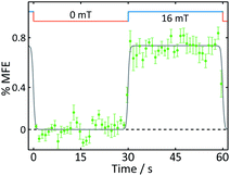 | ||
| Fig. 5 Average %MFE of AtCry1. An applied magnetic field is switched between 0 and 16 mT every ∼30 s. The data show an average of four on-off steps (see ESI† for full data and analysis). A step function was fitted to the data to guide the eye. | ||
Detection of magnetic field effects in crystals
The main driving force for this work is to explore the potential of confocal microscopy in the study of spatially resolved magnetic field effects. Potential applications include the investigation of the field dependence of light-induced processes in living cells and tissues, as well as spintronic materials and devices.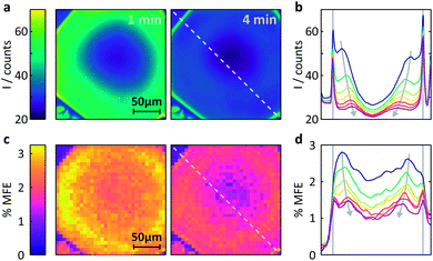 | ||
Fig. 6 Measurement of the MFE on an FMN-doped HEWL crystal by confocal microscopy. (a) Spatially-resolved fluorescence intensity after different times following the onset of continuous illumination at 458![[thin space (1/6-em)]](https://www.rsc.org/images/entities/char_2009.gif) nm. Left t = 1 min, right t = 4 min. (b) Fluorescence intensity profiles across the crystal along the line indicated in (a). The profiles are shown for 1 min time bins (with 45 s offset) after the start of illumination. See ESI† for exact time regions. (c) Time-averaged %MFE of the same crystal in a 16 mT field. The images correspond to the same time bins as in (a). (d) MFE intensity profiles across the crystal along the line indicated in (c) for the same times as for (b). nm. Left t = 1 min, right t = 4 min. (b) Fluorescence intensity profiles across the crystal along the line indicated in (a). The profiles are shown for 1 min time bins (with 45 s offset) after the start of illumination. See ESI† for exact time regions. (c) Time-averaged %MFE of the same crystal in a 16 mT field. The images correspond to the same time bins as in (a). (d) MFE intensity profiles across the crystal along the line indicated in (c) for the same times as for (b). | ||
(i) Different fluorescence intensities are registered inside and outside the crystal.
(ii) The fluorescence intensity is most intense at the edges of the crystal and drops towards the centre.
(iii) The fluorescence intensity in the whole of the crystal drops with time.
Fig. S10 (ESI)† reports a much larger number of images obtained on this crystal over time and further supports the findings above. Fig. S11† also includes the very first image taken and shows that (i) the fluorescence within the crystal is initially nearly entirely homogeneous, including the crystal edges and (ii) the fluorescence throughout the crystal is much stronger than in the surrounding solution (in agreement with the image taken at one minute, Fig. 6a).
The latter observation is a consequence of the restrictive environment within the crystal and of the attractive Coulomb force between HEWL and FMN slowing the diffusion within the crystal matrix. At the low pH used in our study (pH 4.2), the surface of HEWL (isoelectric point of 11.4, see ESI† for details) is positively charged which results in strong interactions with the negatively charged phosphate group of the FMN molecule.30 Such effects have been observed previously: in solution, the strong interaction between HEWL and FMN resulted in large MFEs on the photogenerated radical pair 3[FMNH˙ TrpH˙+].30 In the system studied here, these strong coulombic interactions result in a much increased fluorescence intensity in the tightly packed HEWL crystal as compared to the weakly concentrated protein solution.40
The temporal evolution of the fluorescence profiles is a consequence of a number of competing effects.41,42 Firstly, unlike what is implied in Fig. 2a, the photochemistry of flavins is not perfectly cyclic. Photoexcitation results in the rapid formation of degradation products. In the absence of electron donors, a photodegradation yield of 7.3 × 10⁻³ was reported for FMN.43 The major photodegradation products are lumichrome and lumiflavin derivatives,43 with the former comprising the dominant contribution. Importantly, the absorbance of lumichrome is negligible at our excitation wavelength of 458 nm so that lumichrome does not contribute to the fluorescence images once formed by photodegradation of FMN.43,44
Secondly, diffusion processes, both of photodegraded products out of the crystal and fresh FMN into areas of photobleached crystal, are complex. The importance of diffusion and its intricate interplay with spin dynamics and photobleaching have only in part been explored before, albeit for different photosensitisers, illumination and diffusion conditions.41,42,45 As the emphasis of this paper is on the detection of MFEs (see below), a detailed diffusional analysis is not presented but prepared for publication elsewhere.
Here, a semi-quantitative analysis, taking into account the results of previous studies on similar systems, will suffice. Firstly, as the bright edges appear symmetrically and only in the later (partially photobleached) images, they are unlikely to be optical artefacts but rather illustrate the discrepancy between the diffusion constants of FMN inside and outside the crystal.41 The diffusion coefficient of FMN in aqueous solution has been determined as 5.57 × 10⁻¹⁰ m2 s−1 in work by Tzedakis et al.46 This is three orders of magnitude larger than the diffusion coefficient inside the crystal, as determined by our fluorescence recovery after photobleaching (FRAP) studies (3.4 × 10⁻¹³ m2 s−1, see Fig. 7 for details). The latter is in good agreement with data obtained on fluorescein (a fluorescent probe of similar size and charge to FMN) in HEWL where the diffusion coefficient was found to be between 0.53 and 1.90 × 10⁻¹³ m2 s−1 (depending on crystal direction).42
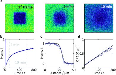 | ||
| Fig. 7 Results of a FRAP experiment and accompanying data analysis to extract the diffusion coefficient of FMN in the HEWL crystals studied. (a) Images of a FMN/HEWL crystal following bleaching of a 40 × 40 μm ROI following intense laser illumination at t = 0. (b) FRAP curve normalised to the intensity before bleaching and corrected for photobleaching due to measurement, see Methods for details. (c) Error function fitted to the edge of the bleached ROI immediately after bleaching. (d) Linear fit of the C parameter defined in eqn (2). | ||
Photobleaching degrades FMN inside both the illuminated solution and the illuminated crystal. However, the bulk volume of surrounding mother liquor solution (∼1 mL) greatly outweighs that of the illuminated (photodegraded) crystal (∼10−7 mL). As a consequence, the concentration of FMN in the bulk liquid can be assumed constant throughout the experiment. Fresh FMN, therefore, continually diffuses rapidly through solution to the (positively charged) crystal surface but slows down significantly within the crystal. Diffusion of FMN inside the crystal is thus the rate-limiting step leading to significant photodegradation and a subsequent fluorescence decrease inside the crystal.
Fig. 6b shows these effects in a different format. Here, the fluorescence count across the crystal (dashed lined in Fig. 6a) is plotted as a function of time (blue to purple traces). The bleaching in the centre of the crystal is obviously most pronounced and rapid due to slow internal diffusion. The edges continue to appear bright as fresh FMN diffuses from solution. Additionally, two symmetric bands of increased fluorescence intensity spread from the sides of the crystal into the centre and decrease in amplitude with observation time. The origin of these bands is presently not entirely clear, but they appear in all flavin-doped HEWL crystals we have studied (see ESI†). Importantly, these bands are not observed when we use either photostable fluorescent probes or dyes whose interactions with HEWL are repulsive, emphasising the importance of both photodegradation and strong probe-crystal interactions in the development of these features.
The temporal evolution of the bands in Fig. 6b emphasises that our system has not reached a steady state and that photobleaching dominates. Decreased illumination intensities reduce the effects of photobleaching but will, in the FMN/HEWL system, lead to significantly reduced quality of the field effect data (see below). However, for systems with cyclic photoschemes such as singlet fission materials, photodegradation is less of an issue.
We finally turn our attention to the investigation of magnetic field effects in FMN-doped HEWL crystals, see Fig. 6c. The field effects are pronounced, showing strong dependence of their magnitude both on the time of observation and position within the crystal. As confirmed by both X-ray crystallography and the FRAP data above, FMN in these systems is not bound, but diffuses within the crystal, albeit less rapidly than in solution. As a result, the system follows the same photocycle as in a solution of FMN and HEWL with the radical pair formed in an initial triplet state. Consequently, the application of a magnetic field reduces the fluorescence yield.
The maximum effects are detected near the edges of the crystals, although the sharp components observed in the fluorescent profiles in Fig. 6a and b above are less prominent. As reported previously, field effects in the FMN/HEWL system are functions not only of FMN concentration and illumination conditions, but also depend strongly on the diffusion rate of the radical pair constituents.20,21 Slower diffusion results in longer radical pair lifetimes which in turn lead to increased magnetic field effects.47 So, whilst, as expected, photodegradation inside the crystal decreases the magnetic field effect, slower diffusion boosts it. As a result, the maximum field effect is observed neither inside the crystal nor at the outside edges but in a band near the crystal–solution interface, where diffusion is neither prohibitively rapid nor photobleaching too extensive.
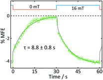
Fig. 8 displays the field effect in different format: here the time- and spatially-averaged response of the FMN doped crystal is shown as a function of time during one “off-on” step. In this figure, it becomes obvious that the field effects observed are dominated by two components. Immediately following the increase of the magnetic field, a prompt MFE develops. Subsequently, the MFE continues to rise slowly with an exponential time constant giving rise to a delayed (enhanced) MFE.21 When the field is switched off, a complementary pattern of fast and slow phases is observed. These observations are in keeping with previous studies in which such prompt and delayed components in the field effects were described:21 the fast component immediately after the field jump is attributed to the attainment of a new steady state at a rate limited by the bulk re-encounter of the free radicals, whilst the slow component was shown to arise from asymmetrical rates of termination reaction of the two radical pair partners. The time constant we find for this delayed field effect is in good agreement with data obtained by Kattnig et al. on FMN/HEWL solutions of increased viscosity.21
In summary, the study of the FMN-doped HEWL crystals demonstrates that confocal microscopy offers insights into the spatiotemporal evolution of magnetic field effects not accessible by any other technique presently employed for MFE studies. Here, photodegradation and diffusion dominate much of the spatiotemporal evolution within the crystals. These processes are likely to be of crucial importance also in other samples (such as cryptochrome-containing cellular systems) and hence warrant detailed examination. They can, however, greatly complicate any efforts of quantitative interpretation and discussion. Moreover, despite the use of a HEWL single crystal, the actual fluorescent probe, on the time scale of the experiment, is mobile, albeit less so than in solution. As a result, it is not possible to study any orientationally-selective field effects in this system.
Anisotropic magnetic field effects in tetracene crystals
To test the suitability of confocal microscopy for the investigation of anisotropic magnetic field effects, we studied photoexcited single crystals of tetracene in magnetic fields of different orientations. Crystals of tetracene (and many other polyacenes) undergo efficient singlet fission to form triplet excitons.48 The yield of the subsequently observed tetracene delayed fluorescence is a function of both the magnitude and orientation of any applied magnetic field, as first demonstrated by Merrifield et al.32Fig. 9a shows the relative fluorescence intensity of a tetracene single crystal in the presence of a 16 mT magnetic field. The ESI† provides a detailed description of the data analysis procedure for this experiment. The clear step increase in the fluorescence intensity coincides with a change in the field direction from parallel (B∥) to perpendicular (B⊥) with respect to the b-axis of the crystal. These data are in agreement with the work by Groff et al. in which the delayed fluorescence intensity was also attenuated when the field was aligned along the b-axis rather than the a-axis.49 However, as Groff's experiments were conducted at 400 mT, we also performed simulations of these effects for the field strength employed here (16 mT). The results depicted in Fig. 9b are in excellent agreement with our experimental findings.
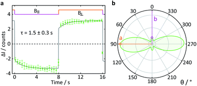 | ||
| Fig. 9 Delayed fluorescence intensity of a tetracene single crystal excited at 458 nm in the presence of a 16 mT magnetic field of different orientations. (a) Response of the fluorescence intensity to a change of field direction from parallel (B∥) to perpendicular (B⊥) with respect to the b-axis of the crystal. The data show the average pixel intensity over the entire frame both time- and position-averaged (see ESI† for details). A single exponential step function with a time constant τ was fitted to both parts of the field cycle to guide the eye. (b) Simulated orientation dependence of the anisotropic component of the delayed fluorescence as a function of angle between the applied magnetic field and the b-axis of the crystal. The orientation dependence of the field effect in tetracene arises from a complex interplay of the Zeeman interaction, the zero-field splitting and kinetic parameters describing the processes of triplet state formation, triplet–triplet annihilation and diffusion of excitons (see ESI†). | ||
Conclusions
With this work, we have demonstrated the exciting potential of confocal microscopy for the investigation of magnetic field effects, not only in homogeneous solutions, but also in solid materials such as single crystals. The latter is enabled by the ability of confocal imaging to reject out-of-focus light and therefore image a single focal plane with high spatial resolution.We employed confocal microscopy to study the spatiotemporal evolution of magnetic field effects in strongly bleaching samples (FMN-doped lysozyme crystals) as well as the anisotropic magnetic field effects in a single crystal of tetracene. We have thus shown that the methodology is equally equipped to study MFEs in systems subject to the RPM as well as those undergoing singlet fission.
Although field effects are conveniently monitored in both systems, some additional considerations will be provided for those studied via their prompt fluorescence. Given the illumination conditions of confocal microscopy, the study of field effects via prompt fluorescence requires the photocycle to be, at least partially, cyclic. Only then will both ground and photoexcited states (and with them the prompt fluorescence) carry the field effect signature.
Particularly large MFEs may develop if radical termination reactions are asymmetrical, and no faster than the time scale of the measurement.21 As shown in Fig. 8, these effects are particularly strong in crystals, attributed to inhibited diffusion. Further, similar long-timescale dynamics (possibly of the same origin) can be seen in the anisotropy of the MFE in tetracene single crystals.
One particularly exciting future application of confocal microscopy is to test ordered samples of cryptochromes for a compass response. Both single crystals of cryptochromes and photoselectively-excited, immobilised cryptochrome samples are attractive targets for these investigations. As the results on AtCry1 have demonstrated, confocal microscopy has the necessary sensitivity to probe the magnetic field sensitive recombination reactions in these proteins. The challenge now is to crystallise these exciting molecules at sufficient size such that confocal microscopy can be employed to test if they are fit for purpose as magnetoreceptors.
Data availability
The data that support the findings of this study are available from the corresponding author C. R. T. on request and have also been deposited in the Oxford University Research Archive (ORA) at http://https://www.ora.ox.ac.uk, DOI: 10.5287/bodleian:y0PgB9BVj.Author contributions
D. A. and C.R.T. conceived the project. V. D. and J. G. performed the experiments. M. K. developed the data analysis code. V. D. and M. K. analysed the data. M. J. G. performed the tetracene simulations. C. G., N. P. and O. F. V. E. pioneered the study of spatiotemporally resolved MFEs. K.-J. T., with technical support from M. O., produced the tetracene crystals. C. R. T. coordinated the study. V. D., M. K., J. G., M. J. G., S. R. M. and C. R. T. interpreted the data. V. D. and C. R. T. wrote the manuscript. All authors discussed the results and commented on the manuscript.Conflicts of interest
There are no conflicts to declare.Acknowledgements
We thank the electronic and mechanical workshops (Department of Chemistry, University of Oxford), and especially Neville Baker, Philip Hurst and Timothy Powell, for the design and construction of the magnetic field apparatus. We are grateful for Dr Charlotte Dodson's assistance with protein expression and purification. We thank Dr Kirsten Christensen and Prof. Susan Lea for the X-ray crystallographic measurements of HEWL crystals. We are grateful to Mr Gabriel Moise for insightful discussions on spin dynamics. Victoire Déjean is indebted to the Clarendon Fund for her doctoral scholarship. Marcin Konowalczyk is thankful to the Air Force Office of Scientific Research (AFOSR, USAF award number FA9550-14-1-0095) for funding of their doctoral studies. Jamie Gravell is funded by the European Research Council (ERC) as part of the QuantumBirds project under the European Union's Horizon 2020 research and innovation programme (Grant agreement No. 810002). Matthew Golesworthy gratefully acknowledges the support of the Biotechnology and Biological Sciences Research Council (BBSRC – grant number BB/M011224/1) and the Clarendon Fund. Dr Ke-Jie Tan gratefully acknowledges support through an A*STAR post-doctoral fellowship provided by Singapore's Agency for Science Technology & Research. Dr M. Oxborrow's work was supported by EPSRC contract EP/K037390/1 (“Manufacturing Routes for Organic Room-Temperature MASER”). Molecular graphics were created with UCSF Chimera, developed by the Resource for Biocomputing, Visualization, and Informatics at the University of California, San Francisco, with support from NIH P41-GM103311.References
- U. E. Steiner and T. Ulrich, Chem. Rev., 1989, 89, 51–147 CrossRef CAS.
- B. Brocklehurst, Chem. Soc. Rev., 2002, 31, 301–311 RSC.
- C. R. Timmel and K. B. Henbest, Philos. Trans. R. Soc., A, 2004, 362, 2573–2589 CrossRef CAS PubMed.
- K. B. Henbest, P. Kukura, C. T. Rodgers, P. J. Hore and C. R. Timmel, J. Am. Chem. Soc., 2004, 126, 8102–8103 CrossRef CAS PubMed.
- A. J. Hoff and J. Deisenhofer, Phys. Rep., 1997, 287, 1–247 CrossRef CAS.
- T. D. Nguyen, J. Rybicki, Y. Sheng and M. Wohlgenannt, Phys. Rev. B: Condens. Matter Mater. Phys., 2008, 77, 035210 CrossRef.
- T. D. Nguyen, Y. Sheng, J. E. Rybicki and M. Wohlgenannt, Sci. Technol. Adv. Mater., 2008, 9, 024206 CrossRef PubMed.
- T. Ritz, S. Adem and K. Schulten, Biophys. J., 2000, 78, 707–718 CrossRef CAS PubMed.
- A. Möller, S. Sagasser, W. Wiltschko and B. Schierwater, Naturwissenschaften, 2004, 91, 585–588 CrossRef PubMed.
- H. Mouritsen, U. Janssen-Bienhold, M. Liedvogel, G. Feenders, J. Stalleicken, P. Dirks and R. Weiler, Proc. Natl. Acad. Sci. U. S. A., 2004, 101, 14294–14299 CrossRef CAS PubMed.
- T. Biskup, E. Schleicher, A. Okafuji, G. Link, K. Hitomi, E. D. Getzoff and S. Weber, Angew. Chem., Int. Ed., 2009, 48, 404–407 CrossRef CAS PubMed.
- K. Maeda, A. J. Robinson, K. B. Henbest, H. J. Hogben, T. Biskup, M. Ahmad, E. Schleicher, S. Weber, C. R. Timmel and P. J. Hore, Proc. Natl. Acad. Sci. U. S. A., 2012, 109, 4774–4779 CrossRef CAS PubMed.
- C. Kerpal, S. Richert, J. G. Storey, S. Pillai, P. A. Liddell, D. Gust, S. R. Mackenzie, P. J. Hore and C. R. Timmel, Nat. Commun., 2019, 10, 3707 CrossRef PubMed.
- R. C. Johnson, R. E. Merrifield, P. Avakian and R. B. Flippen, Phys. Rev. Lett., 1967, 19, 285–287 CrossRef CAS.
- J. P. Beardmore, L. M. Antill and J. R. Woodward, Angew. Chem., Int. Ed., 2015, 54, 8494–8497 CrossRef CAS PubMed.
- K. Maeda, S. R. T Neil, K. B. Henbest, S. Weber, E. Schleicher, P. J. Hore, S. R. Mackenzie and C. R. Timmel, J. Am. Chem. Soc., 2011, 133, 17807–17815 CrossRef CAS PubMed.
- D. M. Sheppard, J. Li, K. B. Henbest, S. R. Neil, K. Maeda, J. Storey, E. Schleicher, T. Biskup, R. Rodriguez, S. Weber, P. J. Hore, C. R. Timmel and S. R. Mackenzie, Sci. Rep., 2017, 7, 42228 CrossRef CAS PubMed.
- Y. Tanimoto, K. Shimizu and M. Itoh, Chem. Phys. Lett., 1984, 112, 217–219 CrossRef CAS.
- S. Richert, A. Rosspeintner, S. Landgraf, G. Grampp, E. Vauthey and D. R. Kattnig, J. Am. Chem. Soc., 2013, 135, 15144–15152 CrossRef CAS PubMed.
- E. W. Evans, J. Li, J. G. Storey, K. Maeda, K. B. Henbest, C. A. Dodson, P. J. Hore, S. R. Mackenzie and C. R. Timmel, Phys. Chem. Chem. Phys., 2015, 17, 18456–18463 RSC.
- D. R. Kattnig, E. W. Evans, V. Déjean, C. A. Dodson, M. I. Wallace, S. R. Mackenzie, C. R. Timmel and P. J. Hore, Nat. Chem., 2016, 8, 384–391 CrossRef CAS PubMed.
- A. A. Lee, J. C. S. Lau, H. J. Hogben, T. Biskup, D. R. Kattnig and P. J. Hore, J. R. Soc., Interface, 2014, 11, 20131063 CrossRef PubMed.
- S. L. J. Tan, J. M. Kan and R. D. Webster, J. Phys. Chem. B, 2013, 117, 13755–13766 CrossRef CAS PubMed.
- P. Dongare, S. Maji and L. Hammarström, J. Am. Chem. Soc., 2016, 138, 2194–2199 CrossRef CAS PubMed.
- C. A. Brautigam, B. S. Smith, Z. Ma, M. Palnitkar, D. R. Tomchick, M. Machius and J. Deisenhofer, Proc. Natl. Acad. Sci. U. S. A., 2004, 101, 12142–12147 CrossRef CAS PubMed.
- E. Pettersen, T. Goddard, C. C. Huang, G. S. Couch, D. M. Greenblatt, E. C. Meng and T. E. Ferrin, J. Comput. Chem., 2004, 25, 1605–1612 CrossRef CAS PubMed.
- M. S. Weiss, G. J. Palm and R. Hilgenfeld, Acta Crystallogr., Sect. D: Biol. Crystallogr., 2000, 56, 952–958 CrossRef CAS PubMed.
- D. Nohr, S. Franz, R. Rodriguez, B. Paulus, L.-O. Essen, S. Weber and E. Schleicher, Biophys. J., 2016, 111, 301–311 CrossRef CAS PubMed.
- P. J. Hore and R. Kaptein, Biochemistry, 1983, 22, 1906–1911 CrossRef CAS PubMed.
- T. Miura, K. Maeda and T. Arai, J. Phys. Chem. B, 2003, 107, 6474–6478 CrossRef CAS.
- R. C. Johnson and R. E. Merrifield, Phys. Rev. B: Solid State, 1970, 1, 896–902 CrossRef.
- R. Merrifield, P. Avakian and R. Groff, Chem. Phys. Lett., 1969, 3, 155–157 CrossRef CAS.
- M. B. Smith and J. Michl, Annu. Rev. Phys. Chem., 2013, 64, 361–386 CrossRef CAS PubMed.
- H. Wang, Y. Zhao, Z. Xie, H. Wang, B. Wang and Y. Ma, CrystEngComm, 2014, 16, 4539–4545 RSC.
- H. Jiang and C. Kloc, MRS Bull., 2013, 38, 28–33 CrossRef CAS.
- D. Aarts and H. Lekkerkerker, J. Phys.: Condens. Matter, 2004, 16, S4231–S4242 CrossRef CAS.
- N. B. Simeonova and W. K. Kegel, Faraday Discuss., 2003, 123, 27–35 RSC.
- S. H. Song, B. Dick, A. Penzkofer, R. Pokorny, A. Batschauer and L. O. Essen, J. Photochem. Photobiol., B, 2006, 85, 1–16 CrossRef CAS PubMed.
- J. Shirdel, P. Zirak, A. Penzkofer, H. Breitkreuz and E. Wolf, Chem. Phys., 2008, 352, 35–47 CrossRef CAS.
- K. Maeda, A. J. Robinson, K. B. Henbest, E. J. Dell and C. R. Timmel, J. Am. Chem. Soc., 2010, 132, 1466–1467 CrossRef CAS PubMed.
- O. D. Velev, E. W. Kaler and A. M. Lenhoff, J. Phys. Chem. B, 2000, 104, 9267–9275 CrossRef CAS.
- A. Cvetkovic, A. J. Straathof, D. N. Hanlon, S. Van Der Zwaag, R. Krishna and L. A. Van Der Wielen, Biotechnol. Bioeng., 2004, 86, 389–398 CrossRef CAS PubMed.
- W. Holzer, J. Shirdel, P. Zirak, A. Penzkofer, P. Hegemann, R. Deutzmann and E. Hochmuth, Chem. Phys., 2005, 308, 69–78 CrossRef CAS.
- A. Tyagi and A. Penzkofer, Photochem. Photobiol., 2011, 87, 524–533 CrossRef CAS PubMed.
- J. Boiden Pedersen and J. H. Freed, J. Chem. Phys., 1973, 58, 2746–2762 CrossRef.
- T. Tzedakis, C. Kane, J. Roche, K. Groenen Serrano and O. Reynes, Electrochim. Acta, 2009, 55, 2286–2294 CrossRef.
- K. Maeda, T. Miura and T. Arai, Mol. Phys., 2006, 104, 1779–1788 CrossRef CAS.
- C. J. Bardeen, Annu. Rev. Phys. Chem., 2014, 65, 127–148 CrossRef CAS PubMed.
- R. P. Groff, P. Avakian and R. Merrifield, J. Lumin., 1970, 2, 218–223 CrossRef.
Footnote |
| † Electronic supplementary information (ESI) available. See DOI: 10.1039/d0sc01986k |
| This journal is © The Royal Society of Chemistry 2020 |

