
 Open Access Article
 This Open Access Article is licensed under a Creative Commons Attribution-Non Commercial 3.0 Unported Licence
Nanostructured liquid-crystalline Li-ion conductors with high oxidation resistance: molecular design strategy towards safe and high-voltage-operation Li-ion batteries†
Atsushi
Kuwabara
a,
Mayu
Enomoto
 a,
Eiji
Hosono
*b,
Kazuma
Hamaguchi
a,
Taira
Onuma
a,
Satoshi
Kajiyama
a and
Takashi
Kato
*a
a,
Eiji
Hosono
*b,
Kazuma
Hamaguchi
a,
Taira
Onuma
a,
Satoshi
Kajiyama
a and
Takashi
Kato
*a
aDepartment Chemistry and Biotechnology, School of Engineering, The University of Tokyo, Hongo, Bunkyo-ku, Tokyo 113-8656, Japan. E-mail: kato@chiral.t.u-tokyo.ac.jp
bNational Institute of Advanced Science and Technology (AIST), Umezono, Tsukuba, Ibaraki 305-8568, Japan. E-mail: e-hosono@aist.go.jp
First published on 23rd June 2020
Abstract
Nanostructured, uncharged liquid-crystalline (LC) electrolyte molecules having bicyclohexyl and cyclic carbonate moieties have been developed for application in Li-ion batteries as quasi-solid electrolytes, which suppress leakage and combustion. Towards the development of safe and high performance Li-ion batteries, we have designed Li-ion conductive LC materials with high oxidation resistance using density functional theory (DFT) calculation. The DFT calculation suggests that a mesogen with a bicyclohexyl moiety is suitable for the high-oxidation-resistance LC electrolytes compared to a mesogen containing phenylene moieties. A tri(oxyethylene) chain introduced between the cyclic carbonate and the bicyclohexyl moiety in the core part tunes the viscosity and the miscibility with Li salts. The designed Li-ion conductive LC molecules exhibit smectic LC phases over a wide temperature range, and they are miscible with added lithium bis(trifluoromethanesulfonyl)imide (LiTFSI) salt up to 5![[thin space (1/6-em)]](https://www.rsc.org/images/entities/char_2009.gif) :5 in molar ratio in their smectic phases. The resulting LC mixtures with LiTFSI show oxidation resistance above 4.0 V vs. Li/Li+ in cyclic voltammetry measurements. The enhanced oxidation resistance improves the performance of Li half-cells containing LC electrolytes.
:5 in molar ratio in their smectic phases. The resulting LC mixtures with LiTFSI show oxidation resistance above 4.0 V vs. Li/Li+ in cyclic voltammetry measurements. The enhanced oxidation resistance improves the performance of Li half-cells containing LC electrolytes.
Introduction
Intensive studies have focused on ion-transport solid and quasi-solid organic materials towards the application particularly in energy-related materials for Li-ion batteries,1–15 solar cells,16–19 and fuel cells20–24 because solid organic materials have light-weight, easy processing, and film-forming properties. These properties are advantageous for versatile large-scale applications, especially for portable and flexible electronics. Recently, ion-transport materials based on liquid crystals have attracted much attention8–10 as organic-based quasi-solid electrolytes that can reduce inherent risks associated with liquid organic electrolytes, for example, leakage, evaporation and combustion. Furthermore, solid and quasi-solid electrolytes suppress dendrite formation that causes short circuiting during charge–discharge reactions.25,26 We have designed liquid-crystalline (LC) molecules having high miscibility with ionic salts and ion conductive properties for use as quasi-solid electrolytes in dye-sensitized solar cells16 and Li-ion batteries.9,10 Nanosegregation between polar and non-polar mesogenic moieties provide efficient ion-conductive pathways in the LC nanostructures8,27 as well as high boiling point and desired viscosities owing to molecular interactions (Fig. 1). The viscosity and ionic conductivity of LC electrolytes can be improved with maintaining LC nanostructures through the supuramolecular approaches.8,10,28 The tuneable quasi-solid features of these molecular assemblies with high viscosities and dynamic ion-conductive moieties afford both high durability and high performance so that LC electrolytes may be used in energy- and environmental-related applications.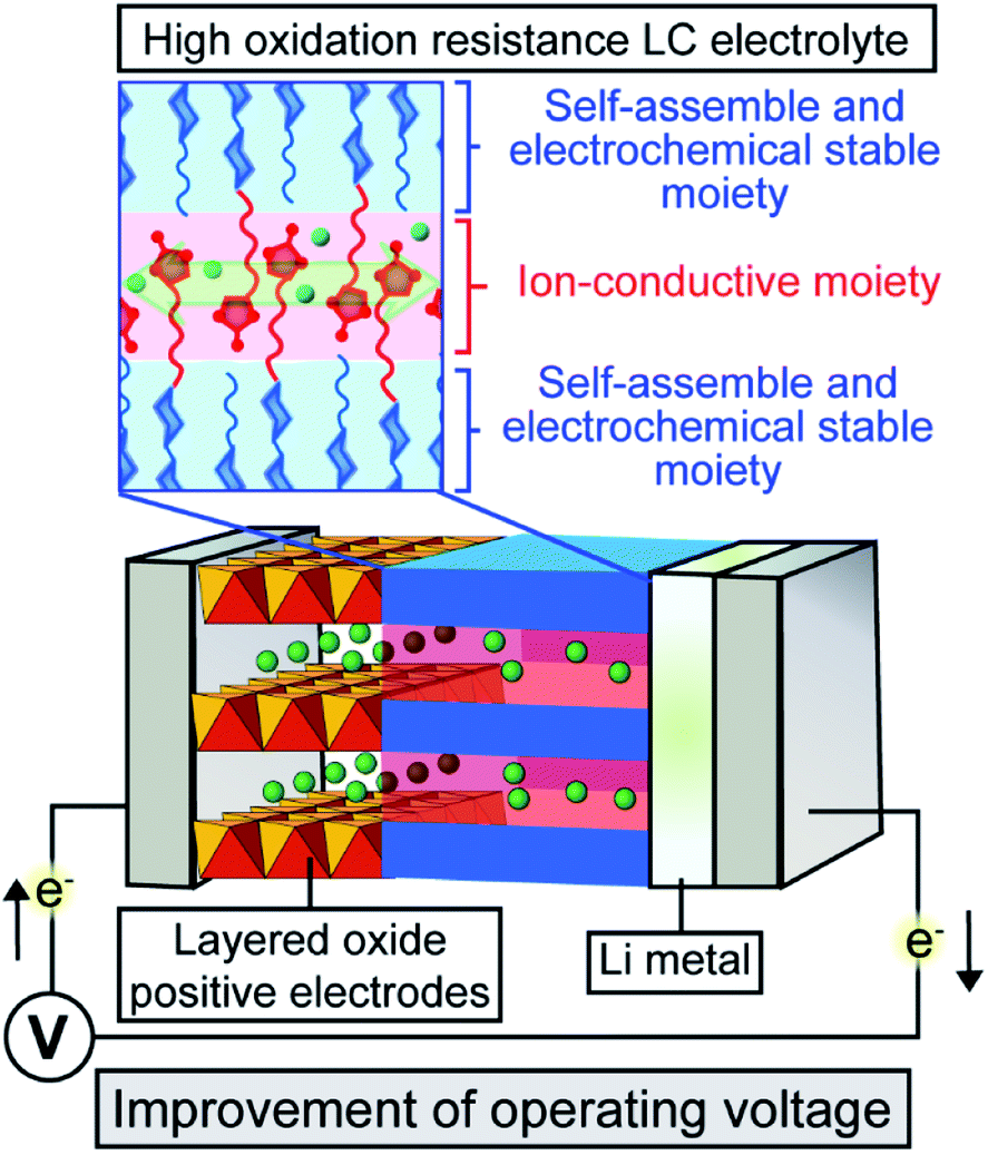 | ||
| Fig. 1 Schematic illustration of Li-ion batteries containing LC electrolytes with ionic conductivity and high oxidation resistance. | ||
Our approach here is to enhance the oxidation resistance of LC electrolytes towards high-voltage-operation Li-ion batteries. The operation voltage of Li-ion batteries is an important factor to determine specific energy and power densities. Because advanced Li-ion batteries require electrochemical stability in the potential range of 0–5.0 V vs. Li/Li+ for full charge–discharge of positive and negative electrode materials, improvement of the oxidation resistance of electrolytes in Li-ion batteries have been studied.29–37 Our previous molecular design for LC electrolytes in Li-ion batteries9 was not sufficient in terms of electrochemical stability.
In the present study, LC molecules 1 and 2 with high electrochemical stability have been designed from a point of view of the highest occupied molecular orbital (HOMO) level calculated using density functional theory (DFT) (Fig. 2). With the respect to the HOMO level, the bicyclohexyl moiety is expected to be an electrochemically stable mesogenic moiety, which induces LC phases over a wide range of temperatures.38,39 The performance of Li-ion batteries using LC mixtures of uncharged molecules of 1 and 2, and added lithium bis(trifluoromethylsulfonyl)imide (LiTFSI) salt was examined by assembling half-cells composed of Li metal and positive electrode materials (Fig. 1). Layered metal oxides were used as positive electrode materials to examine the effects of high-oxidation-resistance of LC electrolyte mixtures on the performance of Li-ion batteries (Fig. 1).
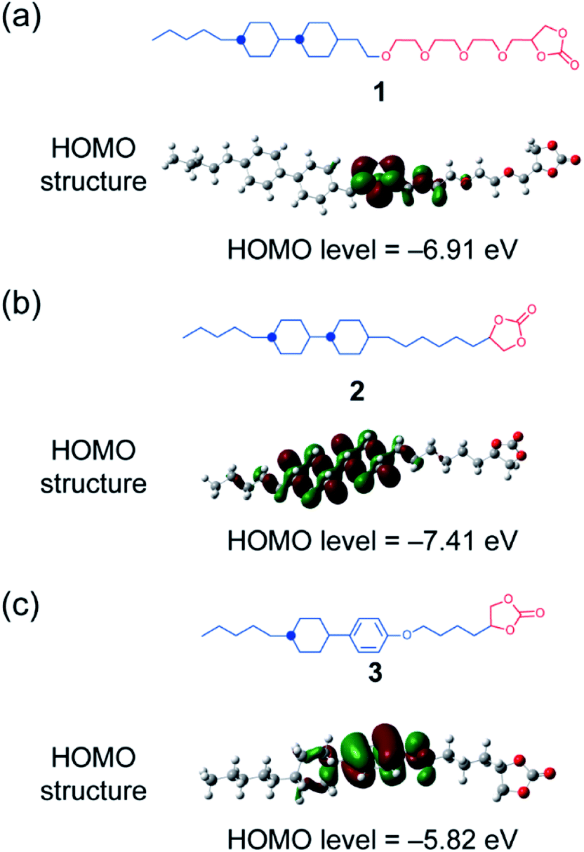 | ||
| Fig. 2 (a and b) Molecular structures and HOMO levels of molecules 1 and 2 in the present study. (c) Compound 3, which was a previously developed LC molecule for the application of electrolytes in Li-ion batteries,9 is shown for reference. | ||
Results and discussion
Uncharged LC molecules 1 and 2 based on a bicyclohexyl moiety were designed and synthesized (Fig. 2a and b). Their HOMO structures were calculated using DFT in order to compare with that of the LC electrolyte with a phenyl cyclohexyl mesogen 3 (Fig. 2c). The HOMO structure of LC molecule 3 was previously studied9 for application to Li-ion batteries. It is localized at an oxygen atom in a phenoxy group, suggesting that this part has a relatively low oxidation resistivity (Fig. 2c). The HOMO level is reduced by the introduction of a bicyclohexyl moiety and removal of the ether oxygen. The oxidation resistance of bicyclohexyl-based LC molecules was confirmed with cyclic voltammetry (CV) measurements of the LC mixture with LiTFSI at the molar ratio of 8:2 (Fig. 3). The bicyclohexyl-based molecule 1 was stable above 4.0 V vs. Li/Li+, while the cyclohexylphenyl-based LC electrolyte electrochemically decomposed at 4.0 V vs. Li/Li+. DFT calculation and CV measurements suggested that the a bicyclohexyl mesogen is a suitable for the application in high-voltage-operation Li-ion batteries as quasi-solid electrolytes.
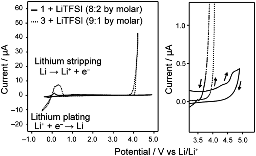 | ||
| Fig. 3 Cyclic voltammograms of the LC electrolytes containing LiTFSI, recorded in the voltage region of −0.5–4.9 V vs. Li/Li+ for 1/LiTFSI and −0.5–4.2 V vs. Li/Li+ for 3/LiTFSI, respectively. Enlarged curves in the high voltage region are shown at the right part. Arrows in the right part indicate the sweep direction of cyclic voltammograms. | ||
The LC properties of compounds 1 and 2 were examined using polarizing optical microscopy (POM), differential scanning calorimetry (DSC) and X-ray diffraction (XRD) (Fig. 4). Compounds 1 and 2 showed POM textures characteristic of smectic phases (Fig. a and b). The dark POM image shown in Fig. 4a and the conoscopic image of a cross extinction (inset of Fig. 4a) suggest homeotropic alignment of the smectic phase. DSC curves show that both compounds 1 and 2 exhibit the smectic phases over a wide temperature range (Fig. 4c and d). The isotropization temperature of 1 was lower than that of 2. The XRD patterns show that lamellar structures were formed in LC states of 1 and 2 (Fig. 4e and f). The interlayer spacings of lamellar structures of 1 and 2 was calculated to be 34.3 and 49.8 Å, respectively. The calculated value of the interlayer space of 1 was similar to the molecular length estimated with molecular mechanics (MM) simulation, suggesting the formation of a monolayer structure. For compound 2, the calculated interlayer spacing was larger about twice than its modelled molecular length, similar to the case of compound 3 bearing cyclohexylphenyl and cyclic carbonate moieties that showed bilayer smectic phases.9 The XRD peaks around 18° suggest ordering along the short-axis direction of molecules through the interaction between bicyclohexyl moieties. For compound 1, because the distance in the short-axis direction was determined to be 4.9 Å, the LC phase was assigned to a smectic B phase.
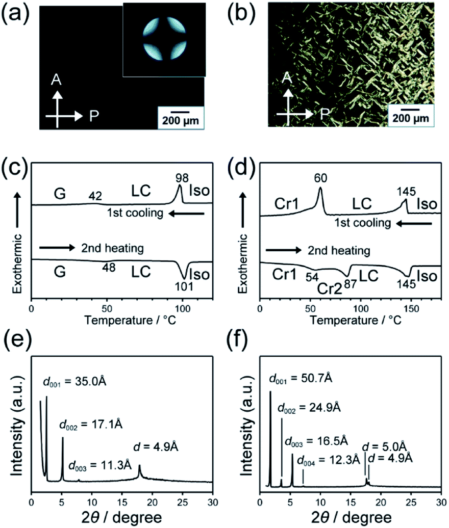 | ||
| Fig. 4 (a and b) POM images of 1 and 2 in LC phases at 60 and 130 °C, respectively. (c and d) DSC thermograms of 1 and 2 recorded at heating and cooling rates of 10 K min−1. Iso: isotropic; LC: liquid crystalline phase; Cr: crystals. (e and f) XRD patterns of LC phases of 1 and 2 measured at 70 and 100 °C, respectively. | ||
Miscibility for the LC molecules 1 and 2 with added LiTFSI was examined with DSC and XRD (Fig. S1 and S2†). Compound 1 and LiTFSI were miscible up to a mole fraction of 0.5 for LiTFSI (Fig. 5a). The mixture of 1/LiTFSI showed smectic phases in a wide range of temperatures, including room temperature (Fig. 5a). In the case of compound 2, additional peaks were observed with the addition of LiTFSI in the XRD measurements, suggesting phase separation (Fig. S3 and S4†). The bicyclohexyl moiety bearing alkyl chains40 induced well-packed structures of molecule 2, which disturbed to incorporate LiTFSI due to their self-assembled ordered structures. Compound 2 and the mixture of 2/LiTFSI showed crystalline phases at room temperature (Fig. 5b). The crystal–smectic transition temperature decreased as the fraction of LiTFSI increased in the mixture.
 | ||
| Fig. 5 Phase diagrams for mixtures of (a) 1 and (b) 2 with LiTFSI, determined with POM observation and DSC on cooling. SmB: smectic B; SmA: smectic A; Sm: unidentified smectic; Iso: isotropic; G: glass, Cr: crystal. | ||
The ionic conductivity of the LC mixture with LiTFSI was measured with an alternative current impedance method using comb-shaped gold electrodes deposited on a glass substrate.9,10 The size change of semicircles in Nyquist plots obtained with alternative current impedance measurements at various temperatures is attributed to temperature dependence of the ionic conductivity of the LC mixtures (Fig. S5†). These results suggest that the ionic conductivity of the LC mixtures increases approximately linearly with increasing temperature. Fig. 6 shows the comparison of ionic conductivities of the LC mixtures of 1–3 with LiTFSI. The LC mixtures of 1 and 2 for evaluation as electrolytes in Li-ion batteries were prepared with molar fractions of 80:20 and 85:15, respectively. These mixtures showed higher ion conductivity values at room temperature than those of other mixtures with different molar composition ratios (Fig. S6†). The LC mixture of 1/LiTFSI showed comparable ionic conductivities to 3/LiTFSI (Fig. 6). For the LC mixture of 2/LiTFSI, its conductivity values were ten times smaller than those of the LC mixtures of 1/LiTFSI and 3/LiTFSI. The ionic conductivities varied with the amount of LiTFSI in the LC mixture of 1 and 2. Increase of volume of ionic moieties and flexibility by the introduction of a tri(oxyethylene) chain cancelled out the effects of the bicyclohexyl moiety decreasing ionic conductivities by the well-packed self-assembled structures. These results suggest that 1/LiTFSI mixtures are suitable more than 2/LiTFSI mixture as electrolytes in Li-ion batteries.
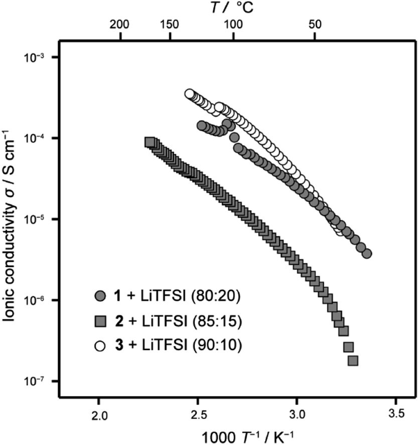 | ||
| Fig. 6 Ionic conductivities of LC mixtures 1–3 with LiFFSI. | ||
The performance of Li-ion batteries using 1/LiTFSI LC mixture was evaluated with a half-cell composed of positive active electrode materials and Li metal. Positive electrode materials were obtained by coating of the slurry containing an active material, a conductive additive and a binder, on an aluminium foil. The thickness of positive electrode materials was estimated to be 20 μm with SEM observation (Fig. S7†)
The half-cell composed of LiFePO4 and Li metal with the LC mixture of 1 was operated at 60 and 80 °C. Low performance of the half-cells was observed at 60 °C with the current rate of 5 mA g−1 (Fig. S8†). Because of stable packing of the bicyclohexyl moiety,41 the LC electrolyte based on 1 requires higher temperature for the operation than that for LC electrolyte of 3/LiTFSI.9 At 80 °C, the half-cell containing the LC mixture electrolyte of 1/LiTFSI delivered 150 mA h g−1, which was close to the theoretical capacity of LiFePO4 (170 mA h g−1) (Fig. 7a). Significant decrease of the specific capacity was not observed within 30 cycles, suggesting that the 1/LiTFSI was a stable Li-ion electrolyte in the range of 3.8–2.8 V vs. Li/Li+. It is noteworthy that the coulombic efficiency of the half-cell containing the LC electrolytes of 1/LiTFSI was improved to ca. 95% (Fig. 7b), which is higher than that in the case using the LC electrolytes of 3/LiTFSI. These results indicate that high oxidation resistance of 1 suppressed undesired side reactions during charge–discharge reaction, resulting in high coulombic efficiency. Using the LC mixtures of 2/LiTFSI, half-cells cannot be operated because of its high viscosity and low ionic conductivity, which cause the inhibition of Li-ion transport between electrolytes and active materials.
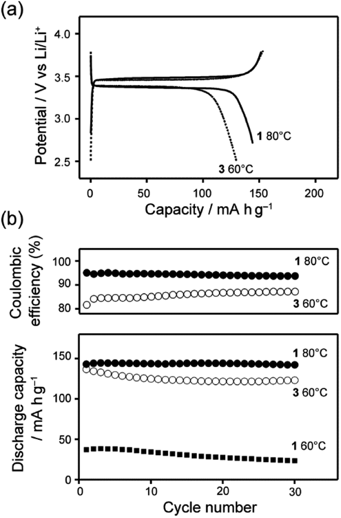 | ||
| Fig. 7 (a) Comparison of representative charge–discharge curves between LC mixture of 1 and LiTFSI (black line) and LC mixture of 3 and LiTFSI (dotted line) at the 5th cycle. (b) Cyclability and coulombic efficiency of Li half-cells using LC electrolytes. | ||
The performance of Li half-cells containing LC electrolyte mixtures of 1/LiTFSI was evaluated using moderate- or high-voltage-operating positive electrode materials, LiCoO2, LiNi0.33Co0.33Mn0.33O2, LiNi0.5Co0.2Mn0.3O2 and LiNi0.815Co0.15Al0.035O2. For positive electrode materials of LiCoO2, LiNi0.33Co0.33Mn0.33O2, LiNi0.5Co0.2Mn0.3O2, the Li half-cells containing 1/LiTFSI exhibited a decrease in performance within 5 cycles (Fig. 8 and S9†). Electrochemical reactions were not stable in the half-cells using LiCoO2 (Fig. 8a). These results suggest that Co atoms with intermediate valence state, which are generated upon the charge–discharge reaction, may catalyse the oxidative degradation of the LC molecules. It is known that ethylene oxide chains can be oxidized by catalytic reaction with intermediate valenced transition-metal atoms.42 The decrease of Co content in active materials improved their cyclability, but significant decreases in performance with cycling were still observed in the case using LiNi0.5Co0.2Mn0.3O2 (Fig. 8b).
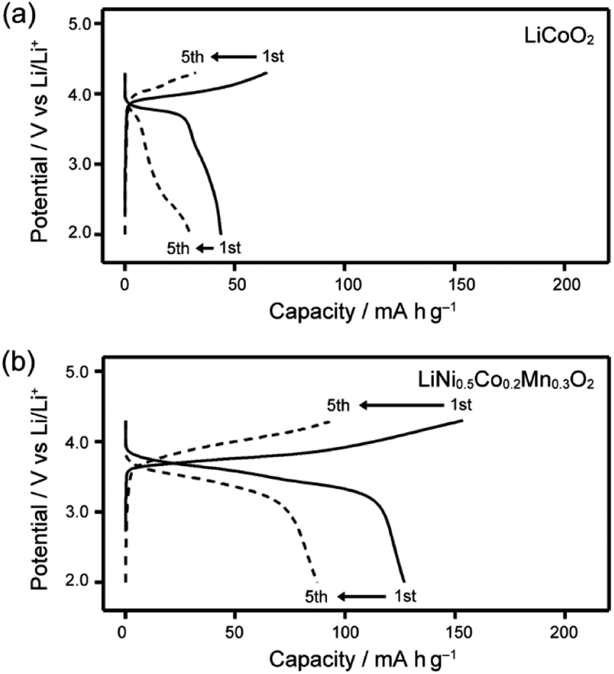 | ||
| Fig. 8 Charge–discharge curves of Li half-cells composed of LC electrolyte 1/LiTFSI and various transition metal positive electrodes recorded at 80 °C; (a) LiCoO2 and (b) LiNi0.5Co0.2Mn0.3O2. | ||
The charge–discharge behaviour using LiNi0.815Co0.15Al0.035O2, i.e., an active material with a relatively small amount of Co, was measured. Improved cyclability of a Li half-cell with this active material containing LC electrolyte 1/LiTFSI was observed (Fig. 9). Comparison of the results for LC electrolyte 1/LiTFSI with those of LC electrolyte 3/LiTFSI suggests that LC electrolyte 1/LiTFSI exhibited sufficient oxidation resistance for electrochemically reversible Li-ion insertion/extraction in the range of 2.5–4.3 V vs. Li/Li+ (Fig. 9). Inconsistent cell performance was observed within 30 cycle (Fig. S10†). This behaviour may be caused by the formation of insulation layers on the surface of the active material during the charge–discharge reactions. Insulation layers were possibly formed by the decomposition of electrolytes causing the formation of solid-electrolyte-interphase (SEI) layer. Furthermore, it is possible that 1/LiTFSI LC electrolyte mixture cannot fill gaps between the particles of the active material, which are generated by the volume and structural change of LiNi0.815Co0.15Al0.035O2 upon the charge–discharge reaction,43 due to the high viscosity of the 1/LiTFSI mixture. The gaps between the electrolyte and particles may serve as an insulation layer. Therefore, the problem in interfaces between active materials and electrolytes could be solved by reduction of particle size, surface treatment, and reduction of viscosity of electrolytes, leading to the realization of high-voltage-operation Li-ion batteries using LC electrolytes.
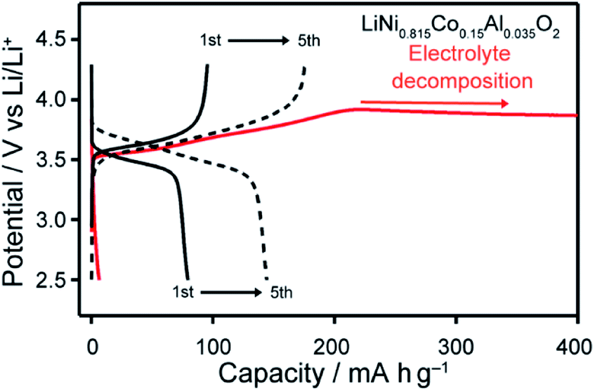 | ||
| Fig. 9 Charge–discharge curves of Li half-cells composed of LC electrolytes of 1/LiTFSI (black) and 3/LiTFSI (red), and LiNi0.815Co0.15Al0.035O2, recorded at 80 °C. | ||
Conclusions
LC electrolytes with high-oxidation-resistance were designed using DFT calculation of HOMO levels. Uncharged LC molecule 1, composed of a bicyclohexyl moiety and a tri(oxyethylene) chain, was miscible with LiTFSI and the mixtures of 1/LiTFSI showed the smectic B phase in a wide range of temperatures including ambient temperature. The mesogen containing a bicyclohexyl moiety provides high-oxidation-resistance to the LC electrolyte mixtures, leading to a good cyclability and higher coulombic efficiency of a LiFePO4/LC electrolyte/Li half-cell. Moreover, the improved oxidation resistance resistivity enabled the electrochemically reversible Li-ion insertion/extraction of LiNi0.815Co0.15Al0.035O2 in the voltage range of 2.5–4.3 V vs. Li/Li+. The synthesis of LC molecules with high-oxidation-resistance based on DFT calculation opens up the possibility of using LC electrolyte materials in high-performance Li-ion batteries. Charge–discharge tests using the LC electrolytes with high oxidation resistance clarified requirements for high-voltage operation, less reactivity of active materials at intermediate valence states and low viscous feature filling gaps between particles.Experimental section
Materials
All the chemicals were purchased from Tokyo Chemical Industry Co., Ltd. (Tokyo, Japan), FUJIFILM Wako Pure Chemical Corporation (Osaka, Japan), Sigma-Aldrich Corporation. (St Louis, MO, USA), Kanto Chemical Co., Inc. (Tokyo, Japan), and used without further purification. Synthetic procedures of intermediates for LC electrolyte molecules, 2-(2-(2-(2-((trans,trans)-4′-pentyl-[1,1′-bi(cyclohexan)]-4-yl)ethoxy)ethoxy)ethoxy)ethan-1-ol and 6-(trans,trans-4′-penthyl-bicyclohexyl)hexyl-1,3-dioxolane-2,2-dimethyl are described in the ESI.†Synthesis of LC electrolyte molecules
:15 (v/v)) as the eluent to afford the compound as white solid (0.50 g, 56% yield). 1H-NMR (400 MHz, CDCl3) δ 4.70 (qd, J = 7.6, 5.5 Hz, 1H), 4.52 (t, J = 8.2 Hz, 1H), 4.06 (dd, J = 8.2, 7.2 Hz, 1H), 1.63–1.75 (m, 10H), 1.22–1.51 (m, 13H), 1.11–1.16 (m, 6H), 0.79–0.98 (m, 14H). 13C-NMR (100 MHz, CDCl3) δ 155.05, 69.36, 43.48, 37.92, 37.86, 37.47, 37.39, 33.89, 33.66, 32.22, 30.09, 30.06, 29.65, 29.55, 29.15, 26.76, 26.66, 24.36, 22.70, 14.10. MS (MALDI-TOF): calcd for [M + Na]+, 429.33; found: 429.06. Elemental analysis calculated (%) for C26H46O3: C, 76.79; H, 11.40; found: C, 76.74; H, 11.64.
Electrochemical measurements
Ion-conductivity measurements
Ionic conductivities were measured by the alternating current impedance method44 with an impedance/gain-phase analyser (Solartron 1260, Hampshire, UK). The LC mixtures with LiTFSI were mounted on comb-shaped gold electrodes, which was covered with a glass plate with SiO2 microparticle spacers (16 μm). Cole–Cole plots were obtained with an applied voltage of 0.3 V in the frequency range from 100 Hz to 1 MHz under temperature control with a hot stage. Ion conductivities were calculated to be the product of 1/R (Ω−1) times cell constants (cm−1) for comb-shaped gold electrodes, which were calibrated with the HI7033L 84 μS cm−1 conductivity standard obtained from Hanna Instruments.Cyclic voltammetry
CR2032-type coin cells were assembled in an argon-filled glovebox using a stainless-steel plate (SUS316L) as the working electrode and Li metal as the counter and reference electrodes. A porous polypropylene film with 25 μm thickness was used as a separator, which was filled with the LC electrolyte mixtures. The electrolytes were spread on the separators prior to the assembly of the cells. The assembled cells were placed in an oven at 120 °C for 15 min to allow the separators to soak up the LC electrolyte mixtures. CV curves were recorded with a Biologic VMP3 multichannel potentiostat (Vaucanson, France) within the potential range of −0.5–4.9 V vs. Li/Li+ at a scan rate of 0.025 mV s−1 at 60 or 80 °C.Charge–discharge experiments
The powder of LiFePO4 (SLFP-PT30, Tianjin STL Energy Technology Co., Ltd., Tianjin, China) as the active material, carbon black (Super P-Li, Imerys Graphite & Carbon, Bironico, Switzerland) as a conductive additive, and poly(vinylidene difluoride) (PVDF#1300, Kureha Corporation, Tokyo, Japan) as a binder were mixed with in N-methyl-2-pyrrolidone with an ultrasonic homogenizer (UH-50, SMT Co., Ltd., Tokyo, Japan) to obtain the slurry of the electrode materials. The weight ratio of the solid materials was 65:30:5. The slurry of other positive electrode materials, LiCoO2 (EQ-Lib-LCO, MTI Cooperation, Tokyo, Japan), LiNi0.33Co0.33Mn0.33O2 (EQ-Lib-LNCM111, MTI Cooperation, Tokyo, Japan), LiNi0.5Co0.2Mn0.3O2 (EQ-Lib-LNCM523, MTI Cooperation, Tokyo, Japan), and LiNi0.815Co0.15Al0.035O2 (EQ-Lib-LNCA810, MTI Cooperation, Tokyo, Japan) were obtained in the similar manner with weight ratios of 60, 30, and 10, respectively. The positive electrodes were prepared by spreading the slurries containing active materials onto an aluminium foil as a current collector, then dried at 100 °C in a vacuum oven over 90 min. CR2032-type coin cells were assembled in an argon-filled glove box using prepared electrodes as a working electrode, Li metal as negative and reference electrodes, and a porous polypropylene film with 25 μm thickness infiltrated with the LC electrolyte mixture as a separator. Galvanostatic charge–discharge curves of the electrode materials were recorded with a Hokuto Denko galvanostat in the appropriate potential ranges. The specific current and capacity were calculated on the basis of the weight of the active materials.
Characterization
The phase-transition behaviour of the LC compounds was observed with DSC (DSC204 Phoenix calorimeter, NETZSCH Geratebau GmbH, Selb, Germany) with ramp rates of 10 K min−1, and POM (BX51, Olympus Co., Tokyo, Japan, with a heating stage (LTS 350, Linkam Scientific Instruments, Ltd., UK)). XRD patterns were recorded with a RINT-2500 diffractometer (Rigaku, Tokyo, Japan) using a Cu Kα source. HOMO levels of molecules were calculated by DFT using Wavefunction Spartan 2010 software. Ground-state geometries were optimised at the Becke's three-parameter hybrid function using the Lee–Yang–Parr correlation functional (B3LYP) level with the 6-31G(d) basis set. For the estimation of molecular lengths, the molecules were minimised to their ground states with MM under a universal force field.Conflicts of interest
There are no conflicts to declare.Acknowledgements
This study was partially supported by JSPS KAKENHI Grant Number JP19H05715 and CREST (Core Research for Evolutional Science and Technology) (JPMJCR1422) of Japan Science and Technology Agency (JST).Notes and references
- F. Croce, G. B. Appetecchi, L. Persi and B. Scrosati, Nature, 1998, 394, 456–458 CrossRef CAS.
- G. S. MacGlashan, Y. G. Andreev and P. G. Bruce, Nature, 1999, 398, 792–794 CrossRef CAS.
- Y. Takeda, N. Imanishi and O. Yamamoto, Electrochemistry, 2009, 77, 784–797 CrossRef CAS.
- R. L. Kerr, S. A. Miller, R. K. Shoemaker, B. J. Elliott and D. L. Gin, J. Am. Chem. Soc., 2009, 131, 15972–15973 CrossRef CAS PubMed.
- N. S. Wanakule, A. Panday, S. A. Mullin, E. Gann, A. Hexemer and N. P. Balsara, Macromolecules, 2009, 42, 5642–5651 CrossRef CAS.
- Y. Zheng, Q. Pan, M. Clites, B. W. Byles, E. Pomerantseva and C. Y. Li, Adv. Energy Mater., 2018, 8, 1801885 CrossRef.
- Y. Zheng, J. Lui, G. Ungar and P. V. Wright, Chem. Rec., 2004, 4, 176–191 CrossRef CAS PubMed.
- T. Kato, M. Yoshio, T. Ichikawa, B. Soberats, H. Ohno and M. Funahashi, Nat. Rev. Mater., 2017, 2, 17001 CrossRef.
- J. Sakuda, E. Hosono, M. Yoshio, T. Ichikawa, T. Matsumoto, H. Ohno, H. Zhou and T. Kato, Adv. Funct. Mater., 2015, 25, 1206–1212 CrossRef CAS.
- T. Onuma, E. Hosono, M. Takenouchi, J. Sakuda, S. Kajiyama, M. Yoshio and T. Kato, ACS Omega, 2018, 3, 159–166 CrossRef CAS PubMed.
- T. Onuma, M. Yoshio, M. Obi, K. Kashiwagi, S. Tahara and T. Kato, Polym. J., 2018, 50, 889–898 CrossRef CAS.
- B. X. Dong, Z. Liu, M. Misra, J. Strzalka, J. Niklas, O. G. Poluektov, F. A. Escobedo, C. K. Ober, P. F. Nealey and S. N. Patel, ACS Nano, 2019, 13, 7665–7675 CrossRef CAS PubMed.
- P.-L. Champagne, D. Ester, D. Polan, V. E. Williams, V. Thangadurai and C.-C. Ling, J. Am. Chem. Soc., 2019, 141, 9217–9224 CrossRef PubMed.
- P.-L. Champagne, D. Ester, A. Bhattacharya, K. Hofstetter, C. Zellman, S. Bag, H. Yu, S. Trudel, V. K. Michaelis, V. E. Williams, V. Thangadurai and C.-C. Ling, J. Mater. Chem. A, 2019, 7, 12201–12213 RSC.
- V. Conejo-Rodríguez, C. Cuerva, R. Schmidt, M. Bardají and P. Espinet, J. Mater. Chem. C, 2019, 7, 663–672 RSC.
- D. Högberg, B. Soberats, R. Yatagai, S. Uchida, M. Yoshio, L. Kloo, H. Segawa and T. Kato, Chem. Mater., 2016, 28, 6493–6500 CrossRef.
- M. A. Kamarudin, A. A. Khan, S. M. Said, M. M. Qasim and T. D. Wilkinson, Liq. Cryst., 2017, 45, 112–121 CrossRef.
- A. Lennert, K. Wagner, R. Yunis, J. M. Pringle, D. M. Guldi and D. L. Officer, ACS Appl. Mater. Interfaces, 2018, 10, 32271–32280 CrossRef CAS PubMed.
- J. V. Vaghasiya, K. K. Sonigara, T. Beuvier, A. Gibaud and S. S. Soni, Nanoscale, 2017, 9, 15949–15957 RSC.
- K. Takakura, Y. Ono, K. Suetsugu, M. Hara, S. Nagano, T. Abe and Y. Nagao, Polym. J., 2019, 51, 31–39 CrossRef CAS.
- A. Concellón, T. Liang, A. P. H. J. Schenning, J. L. Serrano, P. Romero and M. Macros, J. Mater. Chem. C, 2018, 6, 1000–1007 RSC.
- T. Kobayashi, Y. Li, A. Ono, X. Zeng and T. Ichikawa, Chem. Sci., 2019, 10, 6245–6253 RSC.
- O. Kim, K. Kim, U. H. Choi and M. J. Park, Nat. Commun., 2018, 9, 5029 CrossRef PubMed.
- T. Kobayashi, T. Ichikawa, T. Kato and H. Ohno, Adv. Mater., 2017, 29, 1604429 CrossRef PubMed.
- S.-O. Tung, S. Ho, M. Yang, R. Zhang and N. A. Kotov, Nat. Commun., 2015, 6, 6152 CrossRef CAS PubMed.
- S. Wang, X. Liu, A. Wang, Z. Wang, J. Chen, Q. Zeng, X. Jiang, H. Zhou and L. Zhang, ACS Appl. Mater. Interfaces, 2018, 10, 25273–25284 CrossRef CAS PubMed.
- T. Ichikawa, T. Kato and H. Ohno, Chem. Commun., 2019, 55, 8205–8214 RSC.
- J. Sakuda, M. Yoshio, T. Ichikawa, H. Ohno and T. Kato, New J. Chem., 2015, 39, 4471–4477 RSC.
- W. Li, B. Song and A. Manthiram, Chem. Soc. Rev., 2017, 46, 3006–3059 RSC.
- M. Li, J. Lu, Z. Chen and K. Amine, Adv. Mater., 2018, 30, 1800561 CrossRef PubMed.
- T. Kim, W. Song, D.-Y. Son, L. K. Ono and Y. Qi, J. Mater. Chem. A, 2019, 7, 2942–2964 RSC.
- S. Patoux, L. Daniel, C. Bourbon, H. Lignier, C. Pagano, F. Le Cras, S. Jouanneau and S. Martinet, J. Power Sources, 2009, 189, 344–352 CrossRef CAS.
- A. Manthiram, J. C. Knight, S.-T. Myung, S.-M. Oh and Y.-K. Sun, Adv. Energy Mater., 2016, 6, 1501010 CrossRef.
- K. Yoshida, M. Nakamura, Y. Kazue, N. Tachikawa, S. Tsuzuki, S. Seki, K. Dokko and M. Watanabe, J. Am. Chem. Soc., 2011, 133, 13121–13129 CrossRef CAS PubMed.
- J. Wang, Y. Yamada, K. Sodeyama, C. H. Chiang, Y. Tateyama and A. Yamada, Nat. Commun., 2016, 7, 1032 Search PubMed.
- S. A. Khan, S. Ali, K. Saeed, M. Usman and I. Khan, J. Mater. Chem. A, 2019, 7, 10159–10173 RSC.
- S. Choudhury, Z. Tu, A. Nijamudheen, M. J. Zachman, S. Staline, Y. Deng, Q. Zhao, D. Vu, L. F. Kourkoutis, J. L. Mendoza-Cortes and L. A. Archer, Nat. Commun., 2019, 10, 3091 CrossRef PubMed.
- J. Rübesamen and G. M. Schneider, Liq. Cryst., 1993, 13, 711–719 CrossRef.
- R. Cassano, R. Dąbrowski, J. Dziaduszek, N. Picci, G. Chidichimo, G. De Filpo, R. Muzzalupo and F. Puoci, Tetrahedron Lett., 2007, 48, 1447–1450 CrossRef CAS.
- R. Eidenschink, D. Erdmann, J. Krause and L. Pohl, Angew. Chem., Int. Ed. Engl., 1978, 17, 133–134 CrossRef.
- R. Dabrowski, K. Garbat, S. Urban, T. R. Woliński, J. Dziaduszek, T. Ogrodnik and A. Siarkowska, Liq. Cryst., 2017, 44, 1911–1928 CrossRef CAS.
- K. Ueno, J. Murai, H. Moon, K. Dokko and M. Watanabe, J. Electrochem. Soc., 2017, 164, A6088–A6094 CrossRef CAS.
- S. Watanabe, M. Kinoshita, T. Hosokawa, K. Morigaki and K. Nakakura, J. Power Sources, 2014, 258, 210–217 CrossRef CAS.
- B. Soberats, M. Yoshio, T. Ichikawa, X. Zeng, H. Ohno, G. Ungar and T. Kato, J. Am. Chem. Soc., 2015, 137, 13212–13215 CrossRef CAS PubMed.
Footnote |
| † Electronic supplementary information (ESI) available. See DOI: 10.1039/d0sc01646b |
| This journal is © The Royal Society of Chemistry 2020 |