
 Open Access Article
 This Open Access Article is licensed under a Creative Commons Attribution-Non Commercial 3.0 Unported Licence
An electrochemically reversible lattice with redox active A-sites of double perovskite oxide nanosheets to reinforce oxygen electrocatalysis†
Rahul
Majee‡
 ,
Quazi Arif
Islam‡
,
Surajit
Mondal
and
Sayan
Bhattacharyya
*
,
Quazi Arif
Islam‡
,
Surajit
Mondal
and
Sayan
Bhattacharyya
*
Department of Chemical Sciences and Centre for Advanced Functional Materials, Indian Institute of Science Education and Research (IISER) Kolkata, Mohanpur - 741246, India. E-mail: sayanb@iiserkol.ac.in
First published on 7th September 2020
Abstract
The catalyst surface undergoes reversible structural changes while influencing the rate of redox reactions, the atomistic structural details of which are often overlooked when the key focus is to enhance the catalytic activity and reaction yield. We achieve chemical synthesis of ∼5 unit cell thick double perovskite oxide nanosheets (NSs) and demonstrate their precise structural reversibility while catalyzing the successive oxygen evolution and reduction reactions (OER/ORR). 4.1 nm thick A-site ordered BaPrMn1.75Co0.25O5+δ (δ = 0.06–0.17) NSs with oxygen deficient PrOx terminated layers have flexible oxygen coordination of Pr3+ ions, which promotes the redox processes. When subjected to systematic oxidation and reduction cycles by cyclic voltammetry under small electrochemical bias, the PrO1.8 phase appears and disappears alternately at the NS surface, due to the intake and release of oxygen, respectively. The structural reversibility is attributed to the two-dimensional morphology and the A-site terminated surface with flexible anion stoichiometry. Although the underlying B-site cations are well-known active sites, this is the first demonstration of A(Pr3+)-site cations influencing the activity by reversibly altering their oxygen coordination. Higher Co-doping thwarts the NS formation, affecting the catalytic performance. The facile OER/ORR activity of the thickness-tunable NSs has larger implications as a bifunctional air-electrode material for metal–air batteries and fuel cells.
Introduction
Dimensionally confined materials with modulated physicochemical properties hold promise for revolutionizing many technology and industry sectors.1 In particular graphene and its inorganic analogues namely MXenes, transition metal dichalcogenides and other newly discovered layered materials have exhibited significant advancements in applications from energy conversion and storage to biomedicine.2–5 In contrast, the rich spectrum of transition metal oxides especially the perovskite oxides (ABO3) in their two-dimensional (2D) form is limited evidently due to the sustained synthetic challenges.6–8 The method of chemical exfoliation has been the most popular so far; besides, high pressure synthesis and sacrificial layer mediated thin film techniques are also identified to be fruitful.9–13 While 4d or 5d transition metal based layered perovskite structures of Dion–Jacobson, Ruddlesden–Popper and Aurivillius phases are obtained by the exfoliation method,9 the exploration of other 2D perovskite oxide systems with strongly correlated d-orbital electrons is impeded by the expensive physical techniques. Equipped with exotic properties such as high oxygen mobility, extensive stoichiometric range, redox flexibility and thermal stability, the applications of perovskites span a rich spectrum of high temperature superconductivity,14 colossal magnetoresistance,15,16 ferroelectricity,17 high dielectric constant,18 sensing,1 fuel cells,19,20 electrocatalytic conversion,21,22 and storage.23,24 Planar manifestation of this outstanding class of complex oxides, especially with first row transition metals, by avant-garde methods is expected to imbibe state-of-the-art fundamental properties leading to newer functionalities and devices.ABO3 type systems exhibit different crystal structures based on the number of basic units per unit cell. Among these, double and triple perovskite structures impart incremental base units along the c-axis by sharing the axial oxygen atoms between two adjacent motifs.25–28 The cation ordered layered structure provides O2− transport channels,26,29 and this O2− ion mobility makes them viable as out-of-the-ordinary catalysts in many electrochemical energy devices where oxygen electrolysis is the key aspect. Yet the inevitable high temperature synthesis lacks the finesse to produce well-coordinated uniform-sized particles which in turn reduces the usable active sites.21 Although electrospinning can be a remedial approach,30,31 atomistic control of the intriguing properties can be attained by modulating the electronic environment, surface chemistry and other structural features in 2D architectures.6,9,10 High surface area and edge-rich features particularly make the 2D versions better electrocatalysts with facile inplane and transverse oxygen mobility, expectedly accompanied by concomitant reversible activity under redox electrochemical bias. The synthetic challenge however remains in breaking the crystal symmetry and promoting an anisotropic growth of the perovskite oxide lattice, because of which the literature is limited to only a few reports on 2D systems,6,8,9 though not considering the layered perovskites.9
Moving beyond the common exfoliation method to a chemical synthesis route for providing precise tunability to the 2D perovskite, in this work we show the successful synthesis of tetragonal, A-site cation ordered double perovskite oxide, BaPrMn2−xCoxO5+δ, (BPMC; x = 0–1.75) NSs. The NS thickness is ∼4.1 nm, corresponding to 5 unit cells, and this thickness is solvent dependent which can be altered by mild sonication. The prime focus of this work is to demonstrate the unprecedented reversibility of the NS crystal lattice under redox electrochemical bias which is immensely beneficial for fuel cells and metal–air batteries where the OER and ORR need to work in tandem during charging and discharging the battery, respectively.23,32 The ex situ structural reversibility bears a striking resemblance with the in situ electrochemical cycles, validated by powder X-ray diffraction (PXRD), electron microscopy and X-ray photoelectron spectroscopy (XPS). The reversible changes in oxygen non-stoichiometry at the NS surface account for the plausible O2 activation ability.
Results and discussion
Structural elucidation
The BPMC NSs were synthesized by the glycine nitrate sol–gel method (see Fig. 1A). The two-step process firstly consists of calcining the charred gel at 950 °C for 5 h in air to obtain the single perovskite phase, followed by its reduction in 5% H2 at 750 °C for 5 h to obtain the double perovskite NSs. Per contra, the B-site was modulated by systematic replacement of Mn by Co keeping all other descriptors unchanged. The crystal structures explored through Rietveld refinement of the PXRD patterns (see Fig. S1 and Table S1†) show that the single perovskite Ba0.5Pr0.5MnO3 (BPM-cal), prepared by calcination at 950 °C, has mixed orthorhombic Ba-doped PrMnO3 (Pnma) and hexagonal BaMnO3−δ (P63/mmc) phases. After H2 reduction, the mixed phases were converted into a double perovskite, BaPrMn2O5+δ (BPM) having a tetragonal crystal structure (P4/mmm). The single to double perovskite transformation is associated with the depletion of oxygen from the PrOx sublattice (see Fig. 1B and C).33 The induction of oxygen vacancies by reduction and a large size mismatch between Ba2+ and Pr3+ ions invoke A-site cation ordering which results in the formation of a layered tetragonal structure consisting of repeating [PrOx]–[MnO2]–[BaO]–[MnO2]–[PrOx] units stacked along the c-axis.26 BPM has a unit cell volume of 119.76 Å3 with lattice parameters, a = 3.8851 Å and c = 7.9343 Å (see Table S1†). Systematic replacement of Mn by Co shrinks the unit cell volume observed from the higher 2θ shift of overlapped (102) and (110) reflections (see Fig. 1D–F). Shrinking of the unit cell may be ascribed to the stronger Co–O bond than Mn–O.34 12.5 at% Co-doping (x = 0.25, BPMC-0.25) results in the shrinkage of cell volume by 3.24 Å3 with lattice parameters, a = 3.8701 Å and c = 7.7692 Å (see Fig. S2 and Table S1†). At up to 50 at% Co-doping (x = 1.0, BPMC-1), the NSs consist of 6.8 wt% BaCO3 impurity whereas 87.5 at% doping (x = 1.75, BPMC-1.75) induces additional impurity phases of BaO2 and metallic Co. The double perovskite phase is least sustainable after total replacement of Mn by Co (BPC) where the crystal structure degrades to multiple metal oxides such as Co3O4 and metallic Co under reducing conditions (see Fig. 1E). While the Co concentration in BPMC-0.25 is optimum both for stabilizing the double perovskite phase and 2D morphology, increasing the Co content is detrimental since Co-containing perovskites have a high thermal expansion coefficient due to easy reduction at the B-site and evaporation of Co.35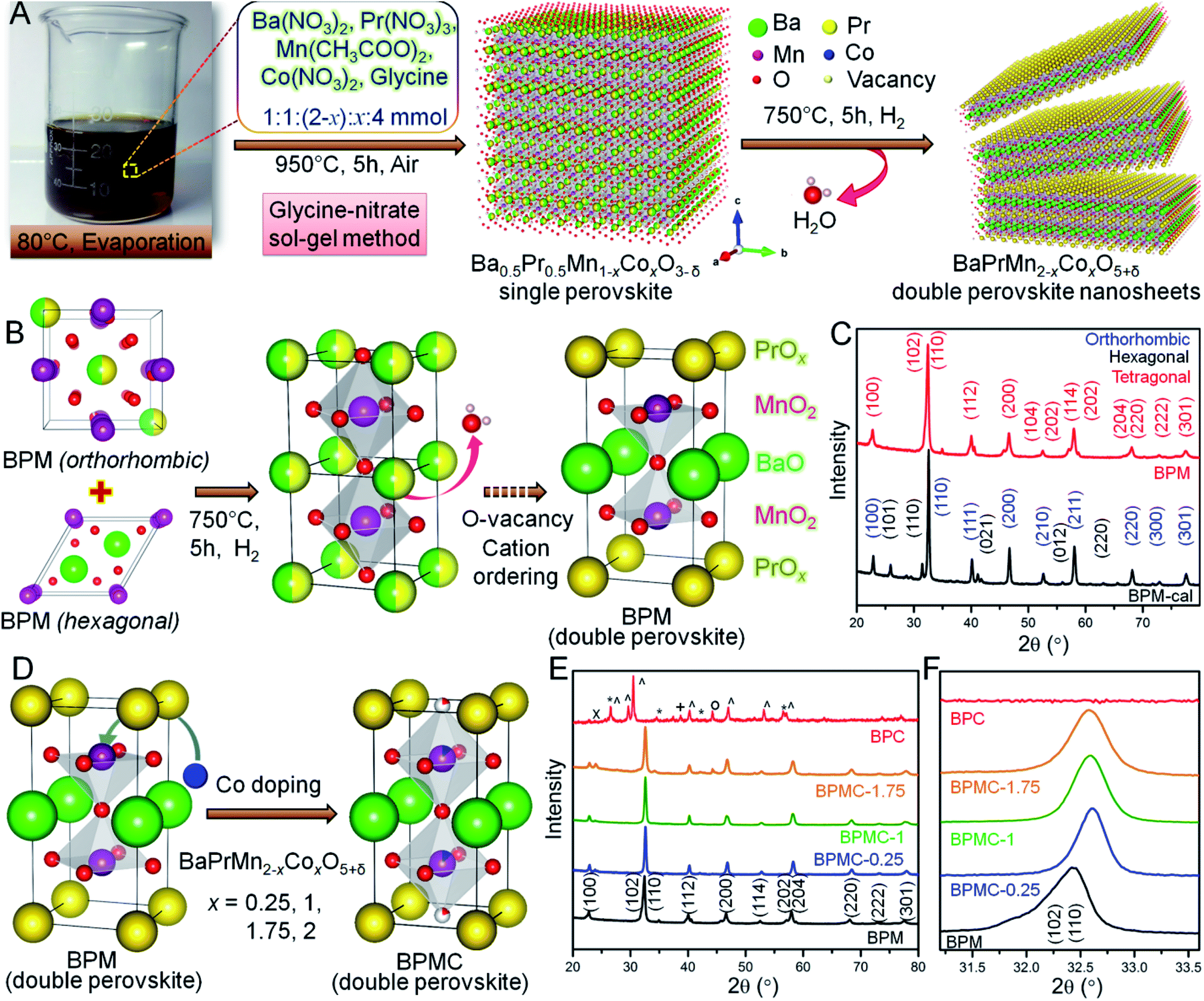 | ||
| Fig. 1 (A) Synthesis schematics of BPMC NSs. (B) Structural schematics showing the conversion of single perovskite to BPM double perovskite. (C) PXRD patterns of BPM-cal and BPM double perovskite. (D) Schematics showing the conversion of BPM to BPMC. (E) PXRD patterns of BPMC NSs with different Co-doping. Symbols denote: (*) BaO2, (^) Pr2O3, (+) Co3O4, (∘) Co, (×) BaCO3. (F) Enlarged view of (110) reflection showing the unit cell contraction by replacement of Mn by Co. | ||
Microscopic analysis
Transmission electron microscopy (TEM), high resolution TEM (HRTEM) and fast Fourier transform (FFT) patterns show ∼100 nm interconnected particles of BPM-cal with concurrence of multiple crystal planes, orthorhombic (110) and hexagonal (100), (200) and (110) reflections (see Fig. S3†). After reduction, the particles transform into ∼100 nm long BPM NSs primarily crystallizing in the tetragonal (100) plane. Up to a critical Co concentration, the NS morphology remains distinct on a statistical average, as in BPMC-0.25 and BPMC-1 (see Fig. S4†), beyond which the NSs start rupturing as in BPMC-1.75 due to the exsolution of excess Co from the perovskite lattice under reducing conditions (see Fig. 1E). The 2D structure is most prominent for BPMC-0.25, where the NSs are 120–150 nm in length (see Fig. 2A). Also the smooth surface topography of BPMC-0.25 NS is evident from field emission scanning electron microscopy (see Fig. S5†). Increasing the ratio of glycine to the metal precursor from 1![[thin space (1/6-em)]](https://www.rsc.org/images/entities/char_2009.gif) :1 to 1.5:1, NSs with shorter lateral dimensions are obtained (see Fig. S6A†), thus emphasizing the crucial role of glycine as a gel forming agent cum fuel in the sol–gel route. The predominating (100) plane is consistent for all Co-doped NSs (see Fig. 2B, S4C, G and K†). The measured d100 spacing which is the distance between neighboring A-site cations, is 0.404 nm for BPM and shrinks to 0.394 nm in BPMC-0.25 (see Fig. 2B), corroborating the Rietveld refinement results (see Table S1†). The FFT pattern in Fig. 2C validates the crystallization of BPMC-0.25 NSs in two prominent crystal planes, (100) and (200). However since the projected plane depends on the viewing direction, FFT mask filter analysis additionally reveals the d-spacing corresponding to (110) and (200) alongside the abundant (100) plane (see Fig. S7†). The relative abundance of (100) weak PXRD reflection compared to the intense (110) plane suggests NS termination by the PrOx layer, since (100) planes are perpendicular to the ab face which contains the PrOx sublattice.36 An isotropic particle growth would have made the (110) plane more prevalent, and likely so in BPMC-1.75 the d-spacing of 0.285 nm (110) over the square patches on the NS surface predominates over 0.372 nm (100) due to the gradual dismantling of the NS morphology (see Fig. S4K and L†). PrOx termination is substantiated by high-angle annular dark-field scanning TEM (HAADF-STEM) elemental line scans which show the highest abundance of Pr and Mn at the NS surface (see Fig. S8†). Considering different possibilities, the ab plane terminated NS surface is observed to be most probable. With 100% cobalt (BPC), the 2D structure is completely disfigured at the advent of multiple metal oxide phases (see Fig. S6B†).
:1 to 1.5:1, NSs with shorter lateral dimensions are obtained (see Fig. S6A†), thus emphasizing the crucial role of glycine as a gel forming agent cum fuel in the sol–gel route. The predominating (100) plane is consistent for all Co-doped NSs (see Fig. 2B, S4C, G and K†). The measured d100 spacing which is the distance between neighboring A-site cations, is 0.404 nm for BPM and shrinks to 0.394 nm in BPMC-0.25 (see Fig. 2B), corroborating the Rietveld refinement results (see Table S1†). The FFT pattern in Fig. 2C validates the crystallization of BPMC-0.25 NSs in two prominent crystal planes, (100) and (200). However since the projected plane depends on the viewing direction, FFT mask filter analysis additionally reveals the d-spacing corresponding to (110) and (200) alongside the abundant (100) plane (see Fig. S7†). The relative abundance of (100) weak PXRD reflection compared to the intense (110) plane suggests NS termination by the PrOx layer, since (100) planes are perpendicular to the ab face which contains the PrOx sublattice.36 An isotropic particle growth would have made the (110) plane more prevalent, and likely so in BPMC-1.75 the d-spacing of 0.285 nm (110) over the square patches on the NS surface predominates over 0.372 nm (100) due to the gradual dismantling of the NS morphology (see Fig. S4K and L†). PrOx termination is substantiated by high-angle annular dark-field scanning TEM (HAADF-STEM) elemental line scans which show the highest abundance of Pr and Mn at the NS surface (see Fig. S8†). Considering different possibilities, the ab plane terminated NS surface is observed to be most probable. With 100% cobalt (BPC), the 2D structure is completely disfigured at the advent of multiple metal oxide phases (see Fig. S6B†).
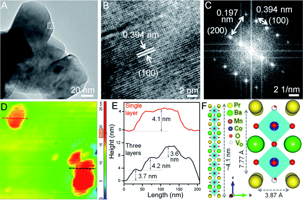 | ||
| Fig. 2 Microscopic elucidation of the NS structure. (A) TEM and (B) HRTEM images of BPMC-0.25 NSs. (C) FFT pattern from the selected region in panel (A). (D) AFM image and (E) corresponding height profiles. Red and black colored plots indicate respective lines of the same color in AFM image. (F) Schematics showing the stack of five unit cells of BPMC-0.25 (left) and a single unit cell (right). | ||
Thickness of BPMC-0.25 NSs
To examine the thickness variation of BPMC-0.25 NSs by atomic force microscopy (AFM), ethanolic dispersions were drop-casted on a cleaned Si wafer after mild bath-sonication for 1–2 min. AFM height profiles show the presence of both single and stacked NSs (see Fig. 2D and E). The average thickness of 150 nm long single NSs is ∼4.1 nm which correlates to 5 unit cells of the BPMC-0.25 lattice (see Fig. 2D–F). 10 min sonication reduces the NS thickness to ∼2 nm but degrades the NS into smaller particles (see Fig. S9A and B†). Using isopropanol, a less polar dispersing medium, results in consistent degradation of the 2D morphology and the NS thickness increases to ∼6.3 nm (see Fig. S9C and D†). The trend is rather abrupt with solvent polarity since in distilled water the NS thickness decreases again to ∼5.8 nm while in nonpolar hexane, the thickness increases to ∼8 nm with larger lateral dimensions (see Fig. S9E–H†). In general, polar solvents help in maintaining the NSs exfoliated since the polar NS surface accommodates solvent binding sites. In this case the confluence of solvent surface tension (γ) and hydrogen bonding ability determines the extent of NS exfoliation.37,38 To achieve better exfoliation, γ should have parity with the low surface energy of the NSs. The thinner NSs in ethanol are due to its lower γ (22.1 mN m−1) while water with higher γ (72.8 mN m−1) results in thicker NSs. On the other hand, isopropanol with similar γ to that of ethanol produces thicker NSs due to lower hydrogen bonding ability which lacks even more in the case of hexane. When the glycine concentration is changed in an ethanol medium, the thickness increases slightly to ∼5.7 nm with 1.5× glycine while 0.5× glycine delivers thicker and bigger NSs (see Fig. S9I–L†).Oxygen non-stoichiometry and ex situ δ variation
Energy dispersive X-ray spectral (EDS) analysis shows a near-perfect match of the elemental ratios with solution stoichiometry (see Table S2 and Fig. S10†). Iodometric titration gives an estimate of the oxygen non-stoichiometry (δ) (see Discussion S1†) whereby all the samples show oxygen stoichiometry of (5 + δ) after reduction inferring almost complete depletion of O atoms from the PrOx layer. The oxygen content is 4.93 ± 0.02, 5.06 ± 0.03, 5.1 ± 0.03 and 4.9 ± 0.01 for BPM, BPMC-0.25, BPMC-1 and BPMC-1.75, respectively (see Fig. S11†). The lower oxygen content in BPM and BPMC-1.75 is due to the exsolution of MnO and Co, respectively. By contrast, the oxygen amount greater than 5 in BPMC-0.25 and BPMC-1 implies partial oxygen abundance in the PrOx plane. Concurrently lower oxygen deficiency in the PrOx plane of BPMC-1 increases the c-axis by 0.02 Å with respect to BPMC-0.25 (see Table S1†). The XPS analysis of BPMC-0.25 NSs shows different chemical states of Pr, Co, Mn and O (see Fig. S12 and Table S3†). In the Pr 3d spectrum, Pr3+ and Pr4+ oxidation states are apparent from the peaks in the 3d5/2 level at 932.6 and 934.8 eV and in the 3d3/2 level at 953.1 and 956.2 eV with relative abundance of 90 and 10%, respectively. Additionally, two peaks at 928.6 and 949.2 eV also represent the Pr3+ state. The deconvoluted Mn 2p spectrum manifests three Mn species viz. Mn2+, Mn3+ and Mn4+ proportionate to 20, 61.8 and 18.2%, respectively. Similarly, the Co 2p level shows 70.2, 24.3 and 5.5% abundance of Co2+, Co3+ and Co4+ states, respectively. Ba2+ incorporation at the A-site should have a direct consequence in promoting higher oxidation states at the B-site beyond 3+, which is however counteracted by the oxygen vacancies and thermal reduction during NS synthesis. XPS analysis thereby shows the effective oxidation state of 2.9+ at the B-site which justifies the 3+ state used for estimation of δ by iodometry. The O 1s spectrum shows three deconvoluted peaks of lattice oxygen, oxygen species surrounding the O-vacant sites and surface adsorbed –OH. The contribution from oxygen vacancies is found to be 1.2 times more than lattice oxygen, which corroborates the above mentioned anion depleted surface structure. To alleviate the oxygen deficiency, BPMC-0.25 was heated under an O2 atmosphere at 500 °C for 1 h (BPMC-0.25-ox/heat) that uplifts δ by 0.11 to B0.5Pr0.5Mn1.75Co0.25O5.17 and brings back the hexagonal BaMnO3−δ impurity (see Fig. S13A and B†). Since oxygen non-stoichiometry is a helpful descriptor for important physicochemical outcomes,39 a flexible oxygen content envisions O2 activation ability of BPMC-0.25 NSs under electrochemical bias.Electrochemical structural flexibility
In view of the NSs being terminated by the oxygen deficient PrOx plane (see Fig. 3A) that can adjust the oxygen stoichiometry under different circumstances, the reversible structure of BPMC-0.25 NSs is studied under 20, 50 and 100 cycles of oxidation and reduction bias (see Fig. 3B). Applying electrochemical redox bias to validate the reversibility in oxygen stoichiometry is a much softer technique than the conventional high temperature conditioning.26,40 Applying cyclic voltammetry (CV), oxidation was performed in O2 saturated 0.1 M KCl electrolyte while only 0.1 M KCl was used for reduction (see Fig. 3C), and the consequences were examined by PXRD. A neutral electrolyte was chosen to avoid any OER and ORR processes and to focus only on the reversible oxygen stoichiometry by supplying minimum electrochemical power. The 20, 50 and 100 cycles of oxidation performed in this study are equivalent to 0.32, 0.8 and 1.6 W, respectively considering 10 mA current while these are one magnitude lower in the case of reduction cycles considering −1 mA current at the working electrode. After 20 oxidative cycles in the range 0 to 0.8 V with respect to the normal hydrogen electrode (NHE), BPMC-0.25 is oxidized to produce oxygen-rich BPMC-0.25 (BPMC-0.25-ox20) along with a new phase PrO1.8 (JCPDS 42-1121) observed at 2θ = 28.2° (see Fig. 3D, S13A and B†). The appearance of PrO1.8 is also consistent at higher oxidative CV cycles in BPMC-0.25-ox50 and BPMC-0.25-ox100. Besides PXRD, the HAADF-STEM line scan shows excess Pr counts at the NS edge of BPMC-0.25-ox20 (see Fig. 3E and F). The NS surface is observed to be dominated by the PrOx sublattice and PrO1.8 phase as compared to the rest of the elements. Subsequent reduction cycles between 0 and −0.8 V curtail the PrO1.8 PXRD peak intensity in BPMC-0.25-ox20/red20 while 50 reduction cycles could completely dissolve this secondary phase in the PrOx sublattice (see Fig. 3D). Readjustment of the PrO1.8 phase within the PrOx sublattice visibly occurs by 100 reduction CV cycles even after 100 oxidation cycles in BPMC-0.25-ox100/red100 (see Fig. S13C and D†). The PrO1.8 phase reappears after another oxidative cycling with the same electrode [ox20 (2)/ox50 (2)/ox100 (2)], accompanied by a Δ2θ ∼ 0.4° low angle shift of the (110) reflection. This shift corroborates the lattice expansion due to insertion of oxygen in the PrOx plane of BPMC-0.25. Due to the insufficient sample mixed with Nafion binder on carbon cloth, iodometric titration could not be used to estimate the oxygen content of samples undergoing electrochemical redox processes. However, Rietveld refinement of PXRD patterns shows the apparent reversibility of the oxygen content through changes in the unit cell volume (see Fig. S13 and Table S4†). For example, after 100 oxidation cycles, the unit cell volume increases by 0.3 Å3 while the c-axis decreases due to the distorted MnO6 energy levels by the Jahn–Teller effect.41 Subsequent 100 reduction cycles decrease the cell volume by 0.4 Å3 and re-oxidation increases it again by 0.5 Å3. Oxygen stoichiometry thereby changes from BPMC-0.25 (5.09), BPMC-0.25-ox20 (5.5), and BPMC-0.25-ox20/red20 (5.2) to ox20 (2) (5.2). Disappearance of the PrO1.8 phase under a reducing atmosphere relates to the removal of weakly bound O as H2O from the PrOx layer of the double perovskite and re-entry of Pr within this sublattice (see Fig. 1A).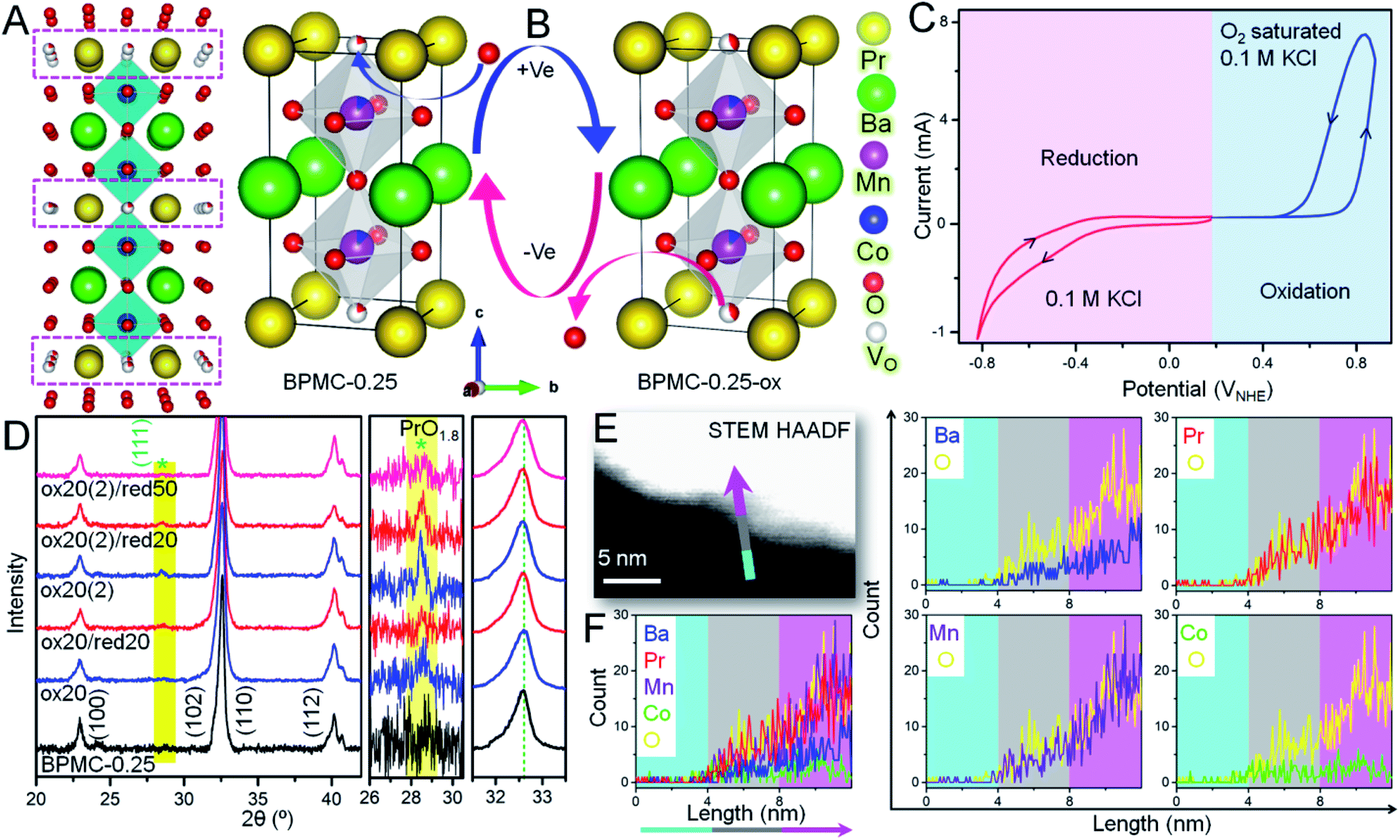 | ||
| Fig. 3 Electrochemical structural flexibility tests of BPMC-0.25 NSs. Schematics of (A) BPMC-0.25 unit cells where pink boxes show the oxygen deficient PrOx layers and (B) structural evolution during electrochemical oxidation and reduction. The oxygen intake in the PrOx layers under positive electrochemical bias is shown by the O spheres having larger red/white color ratio. (C) CV cycles corresponding to oxidation (blue) and reduction (red). (D) PXRD patterns showing the structural changes during successive oxidation and reduction with 20 CV cycles each. The enlarged shaded portion shows the appearance and disappearance/minimization of PrO1.8 phase (*) during oxidation and reduction, respectively. The magnified view of the shift in the (110) position shows the corresponding expansion and contraction of the lattice. (E) HAADF-STEM image of the BPMC-0.25-ox20 (2) surface, where the graded color arrow indicates the direction and position of line scan. (F) Combined and individual elemental line scan results show the surface abundance of Pr relative to other elements. | ||
XPS analyses shed light on the changes in chemical states at the electrochemically reversible NS surface (see Fig. S15 and Table S5†). In BPMC-0.25-ox20, the relative concentration of the Pr4+ state increases by two-fold to 20.3% from 10% in pristine BPMC-0.25. The more abundance of the Pr4+ state relates to the PrO1.8 surface segregated phase in BPMC-0.25-ox20. After electrochemical oxidation, the B-site cations also see an increase in their oxidation states, for example the relative concentration of Mn4+ has increased by 8.4% from the pristine sample, while the increase of the Co4+ state is by 6.1%. Accordingly, the relative abundance of the O-vacant sites is reduced to 0.76 times that of lattice oxygen sites. Moreover, a new peak corresponding to the water molecule is observed from surface adsorption of the electrolyte during CV cycling. XPS analyses provide substantial evidence of the structural reversibility when the Pr4+ concentration is suppressed back to 14.1% after successive reduction cycles. Concurrently the effective oxidation state of the B-site cations is lowered and the relative concentration of O-vacant sites in BPMC-0.25-ox20/red20 increases in comparison to the oxidized sample.
The microstructural reversibility under electrochemical bias is further manifested by TEM analysis (see Fig. S16†) which reveals an unblemished NS surface despite enduring several oxidation and reduction cycles. After 20 oxidation cycles, BPMC-0.25-ox20 shows a new (110) plane of PrO1.8 with a d-spacing of 0.33 nm (Fig. S16A and B†). The corresponding FFT pattern reflects two major lattice constructions, the (110) plane of BPMC-0.25 with a d-spacing of 0.29 nm and (110) of PrO1.8 with a d-spacing of 0.33 nm. After 20 subsequent reduction cycles in BPMC-0.25-ox20/red20, PrO1.8 could not be identified from the interplanar distances and reciprocal lattice points (see Fig. S16D–F†), which is in good agreement with the PXRD pattern (see Fig. 3D). Rather the (100) plane of BPMC-0.25 with a d-spacing of 0.39 nm coexists with the (110) plane. Due to the sublime structural reversibility, the PrO1.8 phase visibly reappears on the NS surface after the next 20 oxidation cycles [ox20 (2)] while the (100) plane of BPMC-0.25 disappears (see Fig. S16G–I†). Because of electrochemical oxidation, oxygen is inserted in the PrOx plane which is likely to strengthen the Pr–O bond. The inherent alterations in the bonding characteristic due to the reversible structural changes of BPMC-0.25 NSs are investigated by Fourier transform infrared (FTIR) spectroscopy (see Fig. S17†). While the indeterminate bands at frequencies greater than 800 cm−1 are due to the surface covered Nafion binder, the metal–oxygen stretching mode at 598 cm−1 broadens and a shoulder at 524 cm−1 is observed after 20 oxidation cycles (BPMC-0.25-ox20). The broadening expectedly vanishes after the reduction cycles for BPMC-0.25-ox20/red20. The electrochemical processes also impact the electrochemically active surface area (ECSA) which corresponds to the double layer capacitance (Cdl). Increasing the oxygen vacant sites at the NS surface by electrochemical reduction cycles increases Cdl, while oxidation and re-oxidation reduce it (see Fig. S18†). Higher Cdl after reduction indicates the formation of catalytically active oxygen vacant sites and partial removal of inactive PrO1.8 from the NS surface.
Effect of structural changes on O2 electrolysis
The surface and structural flexibility of BPMC-0.25 NSs are correlated to facile OER and ORR processes pertinent for metal–air batteries during incessant charging and discharging.23 To test these capabilities within the practical potential window, the NSs with an oxygen deficient and rich PrOx plane, viz. BPMC-0.25, BPMC-0.25-ox50 and BPMC-0.25-ox50/red50 deposited on Ni foil were applied in the OER at 1.2 to 1.8 V and the ORR at 1.0 to 0.2 V, both at 100 mV s−1 scan rate in 0.1 M KOH (see Fig. 4A–C). BPMC-0.25-ox50/red50 shows better OER activity than BPMC-0.25-ox50 while the reverse is true for the ORR. Pristine BPMC-0.25 without any PrO1.8 secondary phase demonstrates the least OER activity and yet has the best prospect in the ORR. The better OER activity of BPMC-0.25-ox50/red50 than BPMC-0.25-ox50 is due to less, ∼2 wt%, catalytically inhibitive PrO1.8 blocking the active sites in the former than 7.7 wt% in the latter. Also oxygen binding or release at the PrOx layer increases or decreases the coordination of B-site cations, respectively. Conventionally higher oxygen content increases the oxidation state of B-site cations which however need to optimize the B-site eg orbital occupancy in order to facilitate the adsorption of reaction intermediates.21 In these 5 unit cell stacked NSs, the oxygen vacancy at the top PrOx layer is large enough for the underlying B-site cations to respond to the reaction intermediates. Although B-site cations are well known active sites in perovskite oxide electrocatalysis, our validation is a first of its kind where oxygen coordination of the A(Pr3+)-site cation is responsible for influencing the catalytic activity. | ||
| Fig. 4 O2 electrolysis with electrochemically oxidized or reduced BPMC-0.25 NSs, deposited on Ni foil. CV plots of (A) OER and (B) ORR with different NSs: BPMC-0.25, BPMC-0.25-ox50 and BPMC-0.25-ox50/red50. The dotted plots in (B) indicate CV cycles in an Ar saturated electrolyte. (C) Bar plots of OER and ORR current densities at fixed potential. (D) PXRD patterns of the BPMC-0.25 electrode to study the structural changes by the OER and ORR after ex situ electrochemical treatments. PXRD plots of the BPMC-0.25 electrode after in situ electrochemical treatments of successive OER and ORR, starting initially by (E) OER and (F) ORR. Insets in (E) and (F) show the successive steps. | ||
Introspection of the (110) reflection in PXRD patterns validates the structural alterations at each experimental step where a shift towards lower 2θ corresponds to lattice expansion due to increase in lattice oxygen at the PrOx plane and vice versa (see Fig. 4D and S19†). During the OER both BPMC-0.25-ox50 and BPMC-0.25-ox50/red50 undergo lattice expansion due to incorporation of oxygen under oxidative bias which oxidizes the B-site followed by O2 evolution. Oxygen insertion is extremely minimal in the already oxidized BPMC-0.25-ox50. The ORR shows a slight shift towards higher 2θ by Δ2θ = 0.02° due to competing factors where entry of oxygen in an O2 environment tends to oxidize the B-site but the predominating negative bias does not allow the lattice binding of excess oxygen. The positive Δ2θ = 0.009° shift from the OER to ORR is more prominent for BPMC-0.25-ox50/red50 where structural reversibility of the catalyst is evident due to minimal active site blocking by PrO1.8. The lattice expansion of pristine BPMC-0.25 although significant after the OER shows a negative Δ2θ shift by 0.03°, and the lattice contraction due to oxygen expulsion post ORR is less apparent due to the above competing factors.
Besides demonstrating the reversible oxygen flux driven ex situ by electrochemical activation, the pristine BPMC-0.25 NSs were subjected to in situ electrochemical redox cycling through two successive cycles of the OER/ORR or the ORR/OER. When the OER is conducted prior to the ORR, the OER process imparts structural robustness to the oxygen coordinated PrOx sublattice and therefore the following ORR step cannot distinctly revert back the oxygen deficient character of BPMC-0.25, reflected from a nearly similar position of the (110) PXRD reflection (see Fig. 4E and S20†). In the second cycle, the OER step results in a slight lattice expansion (negative Δ2θ = 0.003°) and the structure is reverted back by the successive ORR step, evident from a similar but positive Δ2θ shift. The in situ structural reversibility is noticeable in a separate set of experiments where the ORR is conducted first followed by the OER. The OER results in a negative Δ2θ shift by 0.012° due to oxygen insertion in the BPMC-0.25 lattice (see Fig. 4F and S20†). The next ORR step releases the oxygen from the PrOx plane, thus contracting the lattice by Δ2θ = 0.014°. The following OER again expands the lattice by Δ2θ = 0.008°. The oxidation–reduction cycling under electrochemical bias clearly shows the facile insertion and release of oxygen to and from the oxygen deficient PrOx layer of the NSs both in situ and ex situ, and this vivid reversibility is indeed a rare demonstration for any bifunctional catalyst known to date. In fact, this crystal clear illustration is only possible in a few unit cell NS structures, since disintegrating the NSs into smaller nanoparticles with the same crystal phase obscures the signatures by PXRD and electron microscopy.
Oxygen electrocatalysis as a function of cobalt doping
The OER and ORR performance of the NSs as a function of Co-doping reveals the precedence of BPMC-0.25 with 12.5 at% Co-doping.22 The OER overpotential (η) required by the NSs to reach 10 mA cm−2 is 690, 430, 432 and 524 mV for BPM, BPMC-0.25, BPMC-1 and BPMC-1.75, respectively in 1 M KOH with 0.5 mg cm−2 catalyst loading on carbon fiber paper (CFP) (see Fig. 5A). Lowering the Co-doping below 12.5 at% also deteriorates the activity (see Fig. S21†). Notably BPMC-0.25 performs better than the benchmark Ba0.6Sr0.4Co0.79Fe0.21O3−δ (BSCF) with an η of 490 mV.23 BPMC-0.25 exhibits a Tafel slope of 102.4 mV dec−1, the lowest among Co-doped NS catalysts (see Fig. 5B). Although drawing a direct correlation between the Tafel slope and the OER activity trend is inapt, smaller slope values of BPMC-0.25, BPMC-1 and BPMC-1.75 manifest the advantage of Co-doping. Nyquist plots show a charge transfer resistance (RCT) of 18.2 and 17.8 Ω for BPMC-0.25 and BPMC-1, respectively lower than 67.4 Ω for BPMC-1.75 (see Fig. 5C). The abundance of 2D surfaces in BPMC-0.25 and BPMC-1 maximizes the active sites for charge transfer between the electrode and electrolyte. The compatible equivalent circuit shown in the inset of Fig. 5C has five components viz., RCT, series resistance (RS), capacitance (C), constant phase element (CPE) and Gerischer element (G). The Gerischer element signifies charge transfer followed by a chemical change on the electrode surface, which is concomitant to the proclaimed flexible electrochemical surface structure of BPMC-0.25.23 | ||
| Fig. 5 Oxygen electrocatalysis with BPMC and standard catalysts. (A) LSV plots of the OER in 1 M KOH; (B) corresponding Tafel plots and (C) Nyquist plots at a bias of 1.6 V versus RHE. (D) LSV plots of the ORR in 0.1 M KOH, and (E) corresponding Tafel plots. (F) Bar plots showing the bifunctionality index from η values corresponding to 10 and −1 mA cm−2 for the OER and ORR, respectively. | ||
A rotating ring-disk electrode (RRDE) was employed to test the ORR activity in 0.1 M KOH. The LSVs show the best activity of BPMC-0.25 with an η of 584 mV at −1 mA cm−2 (see Fig. 5D and S21†) and the least RCT of 687 Ω (see Fig. S22†). Corroborating the OER performance, BPMC-1 is the next best ORR catalyst with an η of 594 mV. BPMC-0.25 also has better ORR performance than BSCF (η = 612 mV). Even if BPM shows the least ORR activity, it has the finest O2 activation kinetics as shown by the lowest Tafel slope of 210.2 mV dec−1 (see Fig. 5E). Because of the presence of metallic Co and a deformed NS structure, BPMC-1.75 has the highest Cdl of 234.4 μF while BPMC-0.25 and BPMC-1 with intact 2D morphologies and only double perovskite phases have a lower Cdl of 189.4 and 188.2 μF, respectively (see Fig. S23†). Combining the η of OER@10 mA cm−2 and ORR@-1 mA cm−2 depicts the overall scenario for O2 electrolysis, expressed as the bifunctionality index (BI). Lower the value of BI, more is the positive impact on OER/ORR bifunctional activity. BPMC-0.25 shows the lowest BI of 1.01 V, followed by 1.02 V for BPMC-1 (see Fig. 5F). Finally, the chronopotentiometric stability tests of BPMC-0.25 show an almost stable OER performance over 25 h at 10 mA cm−2 (see Fig. S24A†). The activity is suppressed by 91 mV enhancement in η at 10 mA cm2 after 25 h (see Fig. S24B†). Similarly almost stable ORR performance is observed over 5 h at −1 mA cm−2 and post stability, η increases by only 23 mV (see Fig. S24C and D†).
The oxygen electrocatalytic activity of BPMC-0.25 is reasonably on par with the recent reports (see Table S6†),30,42,43 and can be improved further by tuning the lattice by Fe-doping which is however not the prime objective of this study. The advantage of having a 2D morphology with PrOx termination is further manifested when compared to the near-spherical nanoparticles (BPMC-0.25-P) with the same crystallographic phase. BPMC-0.25-P was prepared by dismantling the NSs after 20 min of bath sonication (see Fig. S25†). The OER activity drops with an increase in overpotential by 190 mV at 10 mA cm−2 along with a slight increase in Tafel slope and higher RCT (see Fig. S26A–C†). The ORR activity of BPMC-0.25-P is however better at a relatively lower potential in contrast to the higher potential range, elevating the Tafel slope. Cdl remains similar to that of BPMC-0.25 NSs due to comparable catalytically active surface binding sites (see Fig. S26D–F†). As a proof of concept, the bifunctional BPMC-0.25 NS catalyst loaded onto the cathode of the homemade Zn–air battery manifests a power density of 49.5 mW cm−2 (Fig. S27†). The observed overpotential gap between charge and discharge polarizations is 1.08 V at 10 mA cm−2 which is competent with the reported perovskite oxides.44,45 The device performance can be further improved by improvising the NSs with N-doped carbon nanotubes or reduced graphene oxide composites.46
Conclusions
The atomistic details of the structural reversibility of a 2D double perovskite oxide during electrochemical oxidation and reduction are elucidated. Moving beyond the common exfoliation techniques, the thickness-tunable 4.1 nm thick A-site cation ordered BaPrMn1.75Co0.25O5+δ (δ = 0.06–0.17) NSs having 5 unit cells stacked along the c-axis were synthesized by an original chemical synthesis route. With higher Co-doping, the NS structure disintegrates accompanied by the appearance of secondary impurity phases. In an unprecedented approach, the structural reversibility of the BPMC-0.25 NSs, studied by mild electrochemical oxidation and reduction CV cycles reveals facile exchange of oxygen at the NS surface terminated by an oxygen deficient PrOx plane. Increased oxidation cycles induce the phase segregation of PrO1.8 at the NS surface. Under reductive bias, PrO1.8 is readjusted in the PrOx sublattice. In situ successive OER/ORR cycles demonstrate flexible oxygen coordination at the PrOx plane and an undamped structural reversibility due to lattice expansion by the OER and contraction during the ORR. Besides executing the immaculate details of the reversibility of the NS structure mainly by PXRD, TEM imaging and XPS analysis, the ability to catalyze both the OER and ORR is extremely beneficial for the air-electrode material in metal–air batteries and fuel cells, where BPMC-0.25 exhibits a reasonably low BI of 1.01 V. Conjoining the structural flexibility and oxygen electrocatalytic ability, the electrochemically reversible NS surface is designed to enable low energy oxygen activation. The structural reversibility is attributed to our synthetic methodology that generates thickness-tunable NSs with a minimum number of unit cells stacked along the c-axis. Our approach helps in generalizing the plausible yet advantageous path to modulate the structural and physicochemical properties of 2D perovskite oxides.Conflicts of interest
There are no conflicts to declare.Acknowledgements
R. M. thanks Council of Scientific & Industrial Research (CSIR, File no. – 09/921(0108)/2014-EMR-1), New Delhi, India for his fellowship. Q. A. I. thanks the Science and Engineering Research Board under the Department of Science and Technology, Government of India for his National Postdoctoral Fellowship (PDF/2016/001801). S. M. acknowledges University Grants Commission (UGC), New Delhi, India for his fellowship. The financial support from DST-SERB under sanction no. EMR/2016/001703 is duly acknowledged.Notes and references
- H. Jin, C. Guo, X. Liu, J. Liu, A. Vasileff, Y. Jiao, Y. Zheng and S. Z. Qiao, Chem. Rev., 2018, 118, 6337–6408 CrossRef CAS.
- H. Yang, N. Han, J. Deng, J. Wu, Y. Wang, Y. Hu, P. Ding, Y. Li, Y. Li and J. Lu, Adv. Energy Mater., 2018, 8, 1801536 CrossRef.
- X. Tang, D. Zhou, P. Li, X. Guo, B. Sun, H. Liu, K. Yan, Y. Gogotsi and G. Wang, Adv. Mater., 2020, 32, 1906739 CrossRef CAS.
- T. Foroozan, F. A. Soto, V. Yurkiv, S. Sharifi-Asl, R. Deivanayagam, Z. Huang, R. Rojaee, F. Mashayek, P. B. Balbuena and R. Shahbazian-Yassar, Adv. Funct. Mater., 2018, 28, 1705917 CrossRef.
- A. Bandyopadhyay, P. Yadav, K. Sarkar and S. Bhattacharyya, Chem. Sci., 2019, 10, 6184–6192 RSC.
- D. Ji, S. Cai, T. R. Paudel, H. Sun, C. Zhang, L. Han, Y. Wei, Y. Zang, M. Gu, Y. Zhang, W. Gao, H. Huyan, W. Guo, D. Wu, Z. Gu, E. Y. Tsymbal, P. Wang, Y. Nie and X. Pan, Nature, 2019, 570, 87–90 CrossRef CAS.
- D. Lu, D. J. Baek, S. S. Hong, L. F. Kourkoutis, Y. Hikita and H. Y. Hwang, Nat. Mater., 2016, 15, 1255–1260 CrossRef CAS.
- S. S. Hong, J. H. Yu, D. Lu, A. F. Marshall, Y. Hikita, Y. Cui and H. Y. Hwang, Sci. Adv., 2017, 3, eaao5173 CrossRef.
- M. Osada and T. Sasaki, Dalton Trans., 2018, 47, 2841–2851 RSC.
- C. Cui, F. Xue, W. J. Hu and L. J. Li, npj 2D Mater. Appl., 2018, 2, 18 CrossRef.
- R. Ma and T. Sasaki, Acc. Chem. Res., 2015, 48, 136–143 CrossRef CAS.
- Y. Song, N. Iyi, T. Hoshide, T. C. Ozawa, Y. Ebina, R. Ma, N. Miyamoto and T. Sasaki, Chem. Commun., 2015, 51, 17068–17071 RSC.
- M. Lv, X. Sun, S. Wei, C. Shen, Y. Mi and X. Xu, ACS Nano, 2017, 11, 11441–11448 CrossRef CAS.
- M. H. K. Rubel, T. Takei, N. Kumada, M. M. Ali, A. Miura, K. Tadanaga, K. Oka, M. Azuma, M. Yashima, K. Fujii, E. Magome, C. Moriyoshi, Y. Kuroiwa, J. R. Hester and M. Avdeev, Chem. Mater., 2016, 28, 459–465 CrossRef CAS.
- Y. Tokura, Rep. Prog. Phys., 2006, 69, 797–851 CrossRef CAS.
- A. Sadhu and S. Bhattacharyya, Chem. Mater., 2014, 26, 1702–1710 CrossRef CAS.
- H. Sakai, J. Fujioka, T. Fukuda, D. Okuyama, D. Hashizume, F. Kagawa, H. Nakao, Y. Murakami, T. Arima, A. Q. R. Baron, Y. Taguchi and Y. Tokura, Phys. Rev. Lett., 2011, 107, 1–5 Search PubMed.
- P. Jha, S. Bobev, G. N. Subbanna and A. K. Ganguli, Chem. Mater., 2003, 15, 2229–2233 CrossRef CAS.
- H. L. Zhu, H. Lin, Z. Song, Z. Wang, F. Ye, H. Zhang, W. J. Yin, Y. Yan and W. C. H. Choy, ACS Nano, 2019, 13, 11800–11808 CrossRef CAS.
- O. Celikbilek, C. A. Thieu, F. Agnese, E. Calì, C. Lenser, N. H. Menzler, J. W. Son, S. J. Skinner and E. Djurado, J. Mater. Chem. A, 2019, 7, 25102–25111 RSC.
- R. Majee, S. Chakraborty, H. G. Salunke and S. Bhattacharyya, ACS Appl. Energy Mater., 2018, 1, 3342–3350 CrossRef CAS.
- Q. A. Islam, R. Majee and S. Bhattacharyya, J. Mater. Chem. A, 2019, 7, 19453–19464 RSC.
- R. Majee, Q. A. Islam and S. Bhattacharyya, ACS Appl. Mater. Interfaces, 2019, 11, 35853–35862 CrossRef CAS.
- H. Sun, X. Xu, Z. Hu, L. H. Tjeng, J. Zhao, Q. Zhang, H. J. Lin, C. Te Chen, T. S. Chan, W. Zhou and Z. Shao, J. Mater. Chem. A, 2019, 7, 9924–9932 RSC.
- A. Grimaud, K. J. May, C. E. Carlton, Y. L. Lee, M. Risch, W. T. Hong, J. Zhou and Y. Shao-Horn, Nat. Commun., 2013, 4, 2439 CrossRef.
- T. H. Shin, J. H. Myung, M. Verbraeken, G. Kim and J. T. S. Irvine, Faraday Discuss., 2015, 182, 227–239 RSC.
- N. I. Kim, Y. J. Sa, T. S. Yoo, S. R. Choi, R. A. Afzal, T. Choi, Y. S. Seo, K. S. Lee, J. Y. Hwang, W. S. Choi, S. H. Joo and J. Y. Park, Sci. Adv., 2018, 4, aap9360 CrossRef.
- W. J. Yin, B. Weng, J. Ge, Q. Sun, Z. Li and Y. Yan, Energy Environ. Sci., 2019, 12, 442–462 RSC.
- F. Dong, M. Ni, Y. Chen, D. Chen, M. O. Tadé and Z. Shao, J. Mater. Chem. A, 2014, 2, 20520–20529 RSC.
- Y. Bu, O. Gwon, G. Nam, H. Jang, S. Kim, Q. Zhong, J. Cho and G. Kim, ACS Nano, 2017, 11, 11594–11601 CrossRef CAS.
- B. Zhao, L. Zhang, D. Zhen, S. Yoo, Y. Ding, D. Chen, Y. Chen, Q. Zhang, B. Doyle, X. Xiong and M. Liu, Nat. Commun., 2017, 8, 14586 CrossRef CAS.
- K. Bradley, K. Giagloglou, B. E. Hayden, H. Jungius and C. Vian, Chem. Sci., 2019, 10, 4609–4617 RSC.
- E. Dogdibegovic, N. S. Alabri, C. J. Wright, J. S. Hardy, C. A. Coyle, S. A. Horlick, W. Guan, J. W. Stevenson and X. D. Zhou, J. Electrochem. Soc., 2017, 164, F1115–F1121 CrossRef CAS.
- U. A. Palikundwar, V. B. Sapre, S. V. Moharil and K. R. Priolkar, J. Phys.: Condens. Matter, 2009, 21, 235405 CrossRef.
- Z. Gong, J. Hou, Z. Wang, J. Cao, J. Zhang and W. Liu, Electrochim. Acta, 2015, 178, 60–64 CrossRef CAS.
- Y. Tang, Y. Zhu, Y. Zhang, Z. Zhang and X. Ma, J. Mater. Res., 2013, 28, 1692–1698 CrossRef CAS.
- G. Cunningham, M. Lotya, C. S. Cucinotta, S. Sanvito, S. D. Bergin, R. Menzel, M. S. P. Shaffer and J. N. Coleman, ACS Nano, 2012, 6, 3468–3480 CrossRef CAS.
- J. M. Lee, B. Kang, Y. K. Jo and S. J. Hwang, ACS Appl. Mater. Interfaces, 2019, 11, 12121–12132 CrossRef CAS.
- X. Cheng, E. Fabbri, Y. Yamashita, I. E. Castelli, B. Kim, M. Uchida, R. Haumont, I. Puente-Orench and T. J. Schmidt, ACS Catal., 2018, 8, 9567–9578 CrossRef CAS.
- M. Goto, T. Saito and Y. Shimakawa, Chem. Mater., 2018, 30, 8702–8706 CrossRef CAS.
- A. Sadhu, T. Kramer, A. Datta, S. A. Wiedigen, J. Norpoth, C. Jooss and S. Bhattacharyya, Chem. Mater., 2012, 24, 3758–3764 CrossRef CAS.
- B. Hua, Y. F. Sun, M. Li, N. Yan, J. Chen, Y. Q. Zhang, Y. Zeng, B. Shalchi Amirkhiz and J. L. Luo, Chem. Mater., 2017, 29, 6228–6237 CrossRef CAS.
- N. I. Kim, S. H. Cho, S. H. Park, Y. J. Lee, R. A. Afzal, J. Yoo, Y. S. Seo, Y. J. Lee and J. Y. Park, J. Mater. Chem. A, 2018, 6, 17807–17818 RSC.
- D. U. Lee, H. W. Park, M. G. Park, V. Ismayilov and Z. Chen, ACS Appl. Mater. Interfaces, 2015, 7, 902–910 CrossRef CAS.
- Q. Wang, Y. Xue, S. Sun, S. Li, H. Miao and Z. Liu, Electrochim. Acta, 2017, 254, 14–24 CrossRef CAS.
- R. Majee, S. Mondal and S. Bhattacharyya, Chem. Commun., 2020, 56, 8277–8280 RSC.
Footnotes |
| † Electronic supplementary information (ESI) available. See DOI: 10.1039/d0sc01323d |
| ‡ Equal contribution. |
| This journal is © The Royal Society of Chemistry 2020 |