 Open Access Article
Design of a core–shell catalyst: an effective strategy for suppressing side reactions in syngas for direct selective conversion to light olefins†
Li
Tan
 ab,
Fan
Wang
c,
Peipei
Zhang
b,
Yuichi
Suzuki
b,
Yingquan
Wu
d,
Jiangang
Chen
d,
Guohui
Yang
 *bd and
Noritatsu
Tsubaki
 *b
*b
aInstitute of Molecular Catalysis and Operando Characterization, State Key Laboratory of Photocatalysis on Energy and Environment, College of Chemistry, Fuzhou University, Fuzhou, 350108, China. E-mail: thomas@eng.u-toyama.ac.jp
bDepartment of Applied Chemistry, School of Engineering, University of Toyama, Gofuku 3190, Toyama 930-8555, Japan. E-mail: tsubaki@eng.u-toyama.ac.jp; thomas@eng.u-toyama.ac.jp
cLeibniz-Institut für Katalyse e.V. an der Universität Rostock, Albert-Einstein Strasse 29a, 18059 Rostock, Germany
dState Key Laboratory of Coal Conversion, Institute of Coal Chemistry, Chinese Academy of Sciences, Taiyuan, 030001, China
First published on 18th March 2020
Abstract
An elegant catalyst is designed via the encapsulation of metallic oxide Zn–Cr inside of zeolite SAPO34 as a core–shell structure (Zn–Cr@SAPO) to realize the coupling of methanol-synthesis and methanol-to-olefin reactions. It can not only break through the limitation of the Anderson–Schulz–Flory distribution but can also overcome the disadvantages of physical mixture catalysts, such as excessive CO2 formation. The confinement effect, hierarchical structure and extremely short distance between the two active components result in the Zn–Cr@SAPO capsule catalyst having better mass transfer and diffusion with a boosted synergistic effect. Due to the difference between the adsorption energies of the Zn–Cr metallic oxide/SAPO zeolite physical mixture and capsule catalysts, the produced water and light olefins are easily removed from the Zn–Cr@SAPO capsule catalyst after formation, suppressing the side reactions. The light olefin space time yield (STY) of the capsule catalyst is more than twice that of the typical physical mixture catalyst. The designed capsule catalyst has superior potential for scale-up in industrial applications while simultaneously extending the capabilities of hybrid catalysts for other tandem catalysis reactions through this strategy.
Introduction
C1 chemistry has become a hot research area because one of the most challenging scientific issues is to find alternative energy sources for petroleum in the 21st century. With the development of biomass reforming technology and methane mining technology in shale gas and combustible ice, syngas (a CO + H2 mixture) can be used as a much cheaper stock with larger reserves to synthesize chemicals and energy fuels via a non-petroleum route. Conversion to light olefins (C![[double bond, length as m-dash]](https://www.rsc.org/images/entities/char_e001.gif) 2 to C
2 to C![[double bond, length as m-dash]](https://www.rsc.org/images/entities/char_e001.gif) 4) has attracted immense interest since light olefins are playing more important roles in the chemical industry for a long period.1–3 Light olefins are widely used in the organic chemicals with the largest production volumes all over the world.4 Currently, petroleum resources continue to decrease, which raises barriers for the traditional synthesis of light olefins from naphtha cracking.5,6
4) has attracted immense interest since light olefins are playing more important roles in the chemical industry for a long period.1–3 Light olefins are widely used in the organic chemicals with the largest production volumes all over the world.4 Currently, petroleum resources continue to decrease, which raises barriers for the traditional synthesis of light olefins from naphtha cracking.5,6
To solve this problem, considerable studies on the conversion of syngas (synthesis gas, CO + H2) to light olefins by the Fischer–Tropsch synthesis have been reported due to the cost-effective feeding stock as compared to crude oil, which is called Fischer–Tropsch to olefins (FTTO).7–13 CO can be connected to H2 on the surface of the catalyst and the formation of CHx (x = 1, 2, 3) takes place to convert to CnHm by C–C coupling; finally, the alkane or olefin products are formed by the hydrogenation or dehydrogenation of CnHm. However, the Anderson–Schulz–Flory distribution affects the selectivity for light olefins, which is a maximum of 58% theoretically.5
In another way, light olefins can also be obtained from methanol over a SAPO34 zeolite, namely by the methanol to olefin (MTO) process;14–19 methanol synthesis from syngas has been a mature industrial product since 1923, which was built by BASF.20 Using a hybrid catalyst is also a feasible way to realize the tandem catalysis reaction from complex to simple approaches.21–29 For the above-mentioned findings, a new direct route for syngas to light olefin (STO) synthesis using physical mixture catalysts has been reported.30–36 The light olefin selectivity breaks through the Anderson–Schulz–Flory distribution, which is beyond 58%. Even though it is a discovery of great importance, the challenges of suppressing highly undesirable CO2 selectivity of approximately 50% and uneven mixing of physical mixture catalysts still need to be optimized for its further use in industrialization.
A capsule catalyst with a tailor-made core–shell structure has been designed for several given reactions. Specifically, it can connect two or more consecutive catalytic processes into a direct synthesis. In our previous studies, several successful applications of capsule catalysts have been reported.37–43 For instance, a Co–Al2O3 (core)@H-β-zeolite (shell) capsule catalyst was designed for the direct synthesis of isoparaffins from syngas via the Fischer–Tropsch synthesis. Syngas passes through the zeolite membrane channels to reach the core catalyst, where it forms normal paraffins. These linear hydrocarbons exit by diffusion through the zeolite membrane and those with a straight-chain structure have a chance of being cracked and isomerized at the acidic sites of the zeolite.39 The capsule catalyst (Cu–ZnO–Al2O3 was encapsulated by an H-ZSM-5 layer) for a syngas to DME (CH3OCH3) direct synthesis has also been successfully prepared. The formed methanol on the Cu–ZnO–Al2O3 catalyst from syngas can easily be converted to DME in situ by the H-ZSM-5 layer.40
In this study, the core–shell catalyst comprises metallic oxide Zn–Cr covered by a SAPO34 layer and is used for STO (syngas to light olefins) synthesis. The catalyst is prepared by a modified physical encapsulation method.41–43 With this tailor-made designed catalyst, methanol can form on the metallic oxide Zn–Cr initially, then the methanol will pass through the SAPO34 membrane to dehydrate to light olefins, as illustrated in Scheme 1.
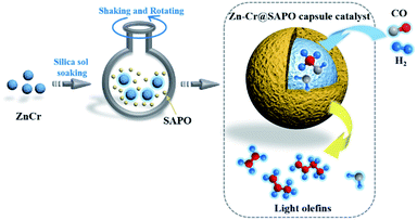 | ||
| Scheme 1 The preparation of a Zn–Cr@SAPO catalyst and the strategy for light olefin synthesis from syngas. | ||
The SAPO34 shell can also protect the metallic oxide Zn–Cr core to block the contact of the formed light olefins and CO2. As a result, the light olefin product has difficulty further hydrogenating into a paraffin on the metallic oxide Zn–Cr. Meanwhile, the water gas shift reaction on Zn–Cr is also limited by SAPO34. A DFT study was performed that clearly shows that the adsorption energies of H2O and C2–C4 light olefins on the SAPO34 shell are greater than on the metallic oxide Zn–Cr core, which provides theoretical evidence for illustrating the protective function of the SAPO34 shell. Herein, in contrast to the regular hybrid or physical mixture catalyst, a capsule catalyst can significantly achieve enhanced light olefin selectivity while limiting CO2 formation successfully.
Results and discussion
Design of active physical mixture catalysts in STO reaction
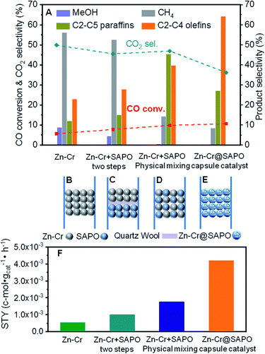
In our study, we first applied a CO hydrogenation catalyst of Zn–Cr prepared by a co-precipitation method for syngas conversion (Fig. 1A and B). The Zn–Cr metallic oxide catalyst is pre-treated and activated by H2 to form oxygen vacancies at temperatures below 400 °C, as given in Fig. S1.†44–48 In the reaction, the selectivity of methanol is as high as 92.58% at 300 °C under 2.0 MPa (Table S2†). In detail, CO is absorbed at the oxygen vacancies then dissociated and hydrogenated by H2 gradually to CH3O, followed by further hydrogenation to methanol. After the formation of oxygen vacancies, the number of electrons and magnetic moments in the vicinity of Zn increases and there are many electrons located above the highest valence band of the oxide.49 Thus, the transfer of these energetic electrons to methoxyl promotes its adsorption at the oxygen vacancies. However, by increasing the temperature (300–450 °C) and pressure (2.0–5.0 MPa), light olefin selectivity reached a maximum of 20% with nearly 50% CO2 produced (Table S1–S3†). It shows that the reaction process has a high barrier to the next MTO step on this sole metallic oxide catalyst. The Zn–Cr metallic oxide does not provide enough active sites for methanol to further dehydrate to light olefins. Thus, the SAPO34 zeolite prepared by a hydrothermal synthesis method was introduced as a C–C coupling catalyst for continuing the light olefin synthesis to realize the STO route. Initially, the SAPO34 zeolite is packed below the Zn–Cr catalyst using a layer of quartz wool to separate these two types of components (Fig. 1A and C). The light olefin selectivity slightly increased to 27.86% but 52.58% of CH4 and 45.50% of CO2 are produced, which is far from the target, as given in Fig. 1A and Table S1.† This may be due to the formed methanol and water on the Zn–Cr metallic oxide, which makes it difficult to attach the SAPO34 zeolite for further tandem catalysis reaction and drainage. The methanol and water are involved more readily in further methanation and the WGS reaction with the CO absorbed on the Zn–Cr metallic oxide defects, according to its thermodynamic equilibrium.50,51In order to accelerate the tandem catalysis process as well as mass transfer and diffusion, two kinds of components were physically mixed as a uniform distribution catalyst to shorten the distance between the two different active phases (Fig. 1D). Several reaction conditions were investigated by varying the space velocity (2160–6480 cm3 h−1 gcat−1); the light olefin selectivity was boosted to 39.70% at most as the space velocity increased (Fig. 1A and Table S1†). These findings prove that shortening the distance of two different active phases is conducive to the light olefin synthesis. Furthermore, from the investigation of the catalyst acidity, the NH3-TPD profiles reveal that the Zn–Cr catalyst has the appropriate acidity to form methanol from CO hydrogenation;52,53 meanwhile, the acidity of the Zn–Cr metallic oxide and SAPO34 zeolite is not too strong to limit the light olefin synthesis, as given in Fig. S2,† because the strongly acidic catalyst will suppress light olefin formation and favour alkanes in the product distribution.54
Design of powerful capsule catalyst to address the problems of physical mixture catalysts
According to the above results, the capsule catalyst was explored for STO synthesis since it has a unique confinement effect, the ability to regulate a tandem-catalysis reaction sequence, and good mass transfer and diffusion performance (Fig. 1E). The Zn–Cr/SAPO weight ratio of the capsule catalyst is 4![[thin space (1/6-em)]](https://www.rsc.org/images/entities/char_2009.gif) :
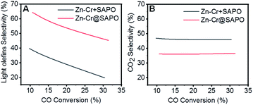
:![[thin space (1/6-em)]](https://www.rsc.org/images/entities/char_2009.gif) 1 according to the ICP results (Table S4†). In the reaction, as shown in Fig. 1A, the light olefin selectivity is significantly enhanced to 64.31% with only 36.16% CO2 formation on the Zn–Cr@SAPO catalyst. Hence, its light olefin space time yield of 4.2 × 10⁻³ c-mol·gcat−1·h−1 is notably higher than that of any other type of catalyst (Fig. 1F). The reason is that the SAPO34 shell of the Zn–Cr@SAPO catalyst prevents the formed light olefins from further hydrogenating into alkanes on the in situ or neighbouring Zn–Cr active sites. At the same time, the SAPO34 shell also protects the Zn–Cr core from further water gas shift (WGS) reactions on the core due to its better water absorbency with larger surface area (Table S4†). It is clear that the capsule catalyst has an advantage over the physical mixture catalyst because of the much higher light olefin selectivity with lower CO2 selectivity at the same CO conversion level (Fig. 2). Consequently, the product distribution favours light olefins while CO2 is greatly suppressed by the synergistic effects and confinement effect of this unique core–shell structured catalyst. Meanwhile, CH4 selectivity is also decreased because the conversion of CH3O species to CH4 is limited in the SAPO34 zeolite shell considering the extremely short distance between the two components, which leads to better mass transfer and MTO-oriented reaction relay.55
1 according to the ICP results (Table S4†). In the reaction, as shown in Fig. 1A, the light olefin selectivity is significantly enhanced to 64.31% with only 36.16% CO2 formation on the Zn–Cr@SAPO catalyst. Hence, its light olefin space time yield of 4.2 × 10⁻³ c-mol·gcat−1·h−1 is notably higher than that of any other type of catalyst (Fig. 1F). The reason is that the SAPO34 shell of the Zn–Cr@SAPO catalyst prevents the formed light olefins from further hydrogenating into alkanes on the in situ or neighbouring Zn–Cr active sites. At the same time, the SAPO34 shell also protects the Zn–Cr core from further water gas shift (WGS) reactions on the core due to its better water absorbency with larger surface area (Table S4†). It is clear that the capsule catalyst has an advantage over the physical mixture catalyst because of the much higher light olefin selectivity with lower CO2 selectivity at the same CO conversion level (Fig. 2). Consequently, the product distribution favours light olefins while CO2 is greatly suppressed by the synergistic effects and confinement effect of this unique core–shell structured catalyst. Meanwhile, CH4 selectivity is also decreased because the conversion of CH3O species to CH4 is limited in the SAPO34 zeolite shell considering the extremely short distance between the two components, which leads to better mass transfer and MTO-oriented reaction relay.55
In particular, the formation of CH3OH or CH4 from intermediate CH3O hydrogenation depends on H donor-attaching C or O on the active surface sites of the Zn–Cr metallic oxide. The reaction channel of the Zn–Cr metallic oxide catalyst to CH3OH has a reaction barrier of 1.33 eV, which is kinetically much more favourable in comparison to CH4 formation with a reaction barrier of 2.41 eV.49 Theoretically, accompanied by CH3OH accumulation on the active sites, the product distribution will shift to CH4 according to the chemical equilibrium between the two competing reactions. Therefore, methane production can be effectively inhibited by the fast scavenging of the accumulated CH3OH over the SAPO34 zeolite shell to obtain target products with high selectivity while decreasing CH4 selectivity.
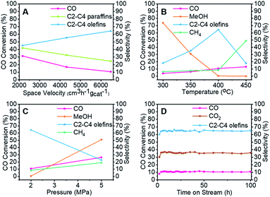
To clarify the influence of the reaction conditions on the STO synthesis with the Zn–Cr@SAPO capsule catalyst, the effects of the temperature, pressure and space velocity were also investigated (Fig. 3, Table S1–S3 and S5†). Light olefin selectivity ranged from 5.06% to 64.31% within the tested temperature (300–450 °C), pressure (2.0–5.0 MPa) and space velocity (2160–6480 cm3 h−1 gcat−1) conditions. The optimum reaction temperature for SAPO34 is 400 °C since more methanol was converted to light olefins as the temperature increased from 300 °C to 400 °C. However, a very high temperature such as 450 °C will drive the products to methane according to the thermodynamics (Fig. 3B). The reaction results also indicate that the hydrogenation ability of the catalyst weakened as the gas flow rate increased. Extending the contact time (decreasing the gas flow rate) for each active site on the catalyst supplies more opportunities for olefin secondary hydrogenation, according to the consecutive reaction kinetics, which alters the product distribution of light olefins (C2–C4 olefins) and paraffins (Fig. 3A). Furthermore, the product distribution profile shifted to light olefins rather than alkanes when the pressure was lower (Fig. 3C), which indicates that the light olefin synthesis was conducted under the appropriate reaction conditions. The H2/CO ratio of syngas was also studied, as given in Table S5.† In comparison to the reaction results under syngas (H2/CO ratio of 2), the methane selectivity increased to 18.45% from 8.39%, partly inhibiting the formation of light olefins at the lower H2/CO ratio. However, there was no distinct difference in the CO2 selectivity. The water formation was inevitable due to the dehydration route for the light olefin synthesis from methanol. It is necessary to synthesize methanol from syngas in the initial stage, which differs from other Fischer–Tropsch routes. To realize methanol synthesis, each CO molecule needs two hydrogen molecules. If there is not enough hydrogen, it is hard to initiate methanol synthesis. As a competitive reaction, more side products will be produced, inhibiting the final light olefin formation. Therefore, it is concluded that the evaluated H2/CO ratio of 2 is necessary for our catalysts to realize a highly efficient direct synthesis of light olefins from syngas. As known, the strongly acidic catalyst will suppress light olefin formation, favouring alkane formation.54 Zeolite acidity, the hydrogenation ability of the core catalyst, and hydrogen pressure determine the final olefin selectivity.
Two samples were prepared and studied to verify the effects from the silica sol. The Zn–Cr catalyst and SAPO-34 zeolite were moistened separately by the diluted silica sol, followed by drying and calcining. In Table S6,† the reaction results suggest that trace Si from the silica sol has no effect on the catalysts or their catalytic performance because the Si concentration in both catalysts is extremely low in the induced diluted silica sol during the catalyst preparation. It had a negligible influence on the acidity of the catalysts according to the NH3-TPD results (Fig. S3†).
The capsule catalyst was also used in a syngas conversion reaction for 100 continuous hours to evaluate its catalytic stability (Fig. 3D and S4†). The Zn–Cr@SAPO capsule catalyst had very stable CO conversion and target product selectivity during this period, which reveals that the catalyst possesses a steady core–shell structure in the STO reaction. To identify whether there were coke deposit species on the catalyst surface, thermogravimetric analysis, Raman and UV-vis spectroscopy were employed to test the used catalysts (Fig. S5 and S7).† All the results suggest that there was no amorphous carbon and graphitic carbon deposition in the spent catalysts. The good catalytic performance of the Zn–Cr@SAPO capsule catalyst also demonstrates its potential for further scale-up in industrial applications.
In-depth and comparative study of the capsule and physical mixture catalysts
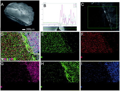
Further studies were performed to understand the unique catalytic functions of the Zn–Cr@SAPO catalyst. Fig. S8† renders the XRD patterns of the catalysts. For the Zn–Cr@SAPO catalyst, the peaks appearing in the range of 30°–45° are attributed to non-stoichiometric spinel ZnxCr2/3(1−x)O; the minor peaks appearing in the range of 5°–30° are attributed to zeolite SAPO34, indicating that the two different components are combined within an integrated catalyst successfully. In the tested samples, the particle size of the catalyst is about 1–2 mm, possessing complete structure. In the tested Zn–Cr@SAPO catalyst, each particle size is about 1–2 mm, possessing an intact core–shell structure. Moreover, the 2D-XRD also shows an obvious thermal signal for non-stoichiometric spinel ZnxCr2/3(1−x)O in the Zn–Cr and SAPO34 physical mixture catalyst (Fig. S9†). However, the signal is much weaker in the Zn–Cr@SAPO capsule catalyst too. This is further evidence that the capsule catalyst with a confined structure was prepared successfully. Meanwhile, the capsule catalyst has the same crystal orientation because of the observed similar Debye rings in both catalysts, which indicates that the Zn–Cr@SAPO catalyst is successfully synthesized without structural damage via the encapsulation method.The surface morphology of the Zn–Cr@SAPO capsule catalyst was analyzed by FE-SEM and SEM (Fig. 4, S10 and S11†). The Zn–Cr surface is totally covered by a SAPO34 layer and no signals were observed from Zn and Cr in the EDS of the Zn–Cr@SAPO capsule catalyst, as shown in Fig. 4A and S11(A and C),† which indicates that the shell of the catalyst is encapsulated well over the core. The EDS linear scan of the cut section in the capsule catalyst (Fig. 4B and S11D†) further demonstrates that the Zn–Cr catalyst is encapsulated by SAPO34 evenly. An obvious boundary between the two different components was observed. The different elements clearly show a boundary line between the Zn–Cr metallic oxide and the SAPO34 zeolite in the mapping pictures (Fig. 4C–I). The thickness of the SAPO34 membrane is about 30–45 μm, which is obtained from Fig. S10 (A and B), and S11 (B and D).† In the EDS analysis given by a frontal horizontal incision photo of the capsule catalyst, the signals of Zn and Cr started to increase from 45 μm beneath the catalyst surface with decreasing Si, Al, and P signals, which gives us the thickness of the SAPO34 shell on the capsule catalyst. This is sufficient for the formation of light olefins from methanol on the catalyst shell. The infinitesimal space between Zn–Cr and SAPO34 is beneficial for the mass transfer and diffusion, which leads to the process of MTO (methanol to light olefins) synthesis on SAPO34 using a methanol immediate that forms on the metallic oxide Zn–Cr. Moreover, the surface of the Zn–Cr metallic oxide component is very smooth and clean, which indicates that the core catalyst was not corroded in comparison with the capsule catalyst synthesized by the routine hydrothermal method. In summary, the Zn–Cr@SAPO capsule catalyst prepared by a physical coating method illustrates superior selectivity of light olefins due to its tailor-made core–shell structure.
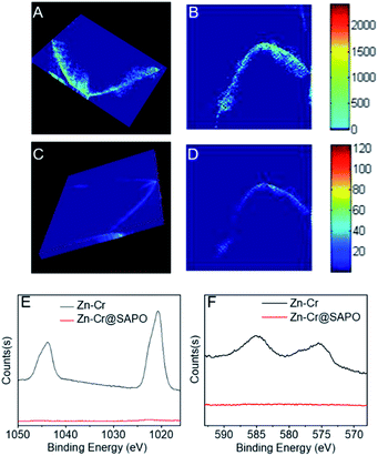
Other strong evidence for the successful preparation of the Zn–Cr@SAPO capsule catalyst without structural damage is the XRF-CT results, as shown in Fig. 5 and S12.†
The prepared capsule catalyst is scanned by horizontal, angular and vertical triple cycle scanning in 9 random positions at a 100 μm depth (Fig. S13†). The fluorescence intensity of Zn and Cr is easily detected over all the positions. The 3-D images also show an even distribution of Zn and Cr inside the Zn–Cr@SAPO capsule catalyst (Fig. 5A and C).56,57 More importantly, at the 100 μm depth of the catalyst, there are no signals for SAPO34 (Si, Al, P), which indicates that there is no corrosion occurring. XPS was also performed to investigate the catalyst surface components (Fig. 5E and F). The photoemission features of the Zn 2p spectrum suggest that the binding energies of Zn 2p1/2 and Zn 2p3/2 are 1045 eV and 1021.5 eV, respectively (Fig. 5E). However, it is difficult to identify the state of Zn by this approach because the binding energy of metallic Zn and cationic Zn are too close to distinguish.58 The photoemission features of Cr 2p3/2 suggest that Cr is only present in the cationic state Cr3+ since the binding energy of Cr 2p3/2 is about 576 eV, which differs from the binding energy of metallic Cr or the cationic state Cr6+ (Fig. 5F).59,60 After H2 activation prior to the STO reaction, the binding energy of Cr 2p3/2 shows a slight downshift to 575.5 eV, which indicates that the state of Cr is a mixture of Cr0 and Cr2+ since the observed binding energy is between the two states (Fig. S14†).
As shown by Fig. S1†, the H2-TPR result has a double overlapping reduction peak in the catalysts, which corresponds to Cr3+ → Cr2+ and small quantities of Cr2+ → Cr0. Combined with the XPS results, it is concluded that the catalyst active sites for methanol synthesis are Zn2+ and Cr0/Cr2+ during the reaction. As a surface-sensitive characterization technique, the signals from the sample in XPS analysis are only detected from the 0–2 nm depth on the catalyst surface. In Fig. 5E and F, no signals of Zn and Cr are observed from the surface of Zn–Cr@SAPO catalyst, which further indicates that the Zn–Cr metallic oxide is covered by a SAPO34 shell.
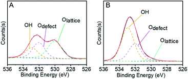
In the first step of STO synthesis, the oxygen vacancy plays a crucial role in the conversion of syngas to methanol. In Fig. 6A, B and Table S7,† after H2 pre-treating of the catalyst for 10 h at 400 °C, the Olattice on the catalyst surface decreased from 43.83% to 2.77%, accompanied with a rapid increase of OH from 21.56% to 63.74%. Simultaneously, the ratio of Odefect/Olattice was obviously enhanced from 0.79 to 12.09, which indicates that the sites supplied by oxygen vacancies favour CO adsorption and continuous activation.44–48 OH increased in the H2-activated Zn–Cr catalyst, which resulted in the adsorption of formed H2O on the catalyst surface from the process of Cr3+ reduction. In general, with increasing syngas (CO/H2) pressure and reaction temperature in the STO reaction, the oxygen vacancies concentration also increased, which was conducive for the release of surface oxygen on the Zn–Cr catalyst in an anaerobic environment. During the period of sustained syngas feeding, unlike the CO adsorption, the positions for H2 adsorption were at the exposed Olattice sites nearby the surface oxygen vacancies.49 Hence, the absorbed CO on the oxygen vacancies can continuously convert into CHO, CH2O, CH3O and CH3OH by attaching to the adjacent H donor.
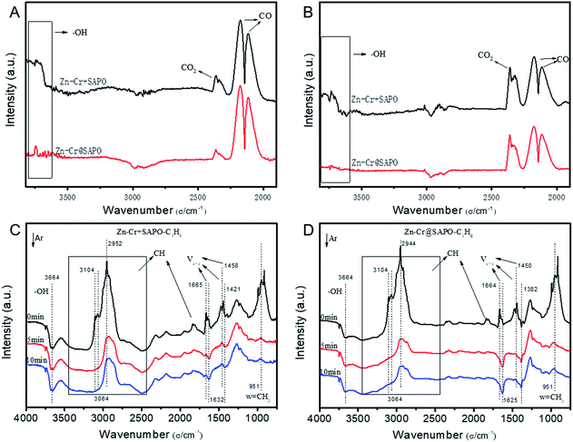
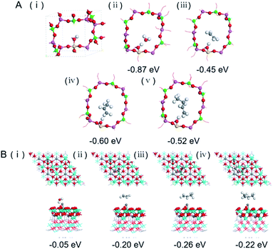
The catalytic behaviour of the physical mixture and capsule catalysts in the presence of syngas was studied by diffuse reflectance infrared Fourier transform spectroscopy (DRIFTS), as illustrated in Fig. 7A and B. The evolution of two peaks at around 2300 cm−1 is attributed to the presence of formed CO2, indicating that the amount of formed CO2 on the capsule catalyst was less than that on the physical mixture catalyst, which suggests that the water gas shift (WGS) reaction is limited by the unique core–shell structure of the Zn–Cr@SAPO capsule catalyst during STO synthesis. In comparison to the vibration peak of the hydroxyl group adsorbed in the two different catalysts, water easily remained in the Zn–Cr phase on the physical mixture catalyst for the continuous WGS reaction. However, the formed water more easily transfers via the SAPO34 shell, which prevents the water from attaching to the Zn–Cr core for further WGS reactions, as shown in Scheme 2. High pressure in situ IR experiments were also performed under the reaction conditions to support this view, as shown in Fig. S15.† The relative amount of the produced CO2 was obviously decreased compared to that of CO in the Zn–Cr@SAPO capsule catalyst. In addition, the DFT calculations also indicate that the adsorption energies of water are much higher on the SAPO34 shell (−0.87 eV, Fig. 8A) than on the Zn–Cr core (−0.05 eV, Fig. 8B). This means the SAPO34 shell has better water absorbency to prevent the WGS reaction from occurring on the Zn–Cr core.
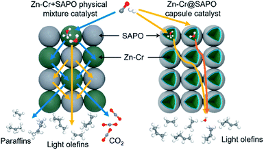 | ||
| Scheme 2 The two different mass transfer routes over the Zn–Cr physical mixture catalyst and capsule catalyst. | ||
The desorption performance of light olefins on the physical mixture and capsule catalysts was simulated under the reaction conditions by DRIFTS, as given in Fig. 7C, D, S16 and S17.† Initially, after the propylene adsorption, the hydrocarbons are more easily adsorbed in the SAPO34 zeolite shell of the Zn–Cr@SAPO capsule catalyst since the π electrons of olefins prefer to be absorbed on the electron-deficient Lewis acid sites of the zeolite. The vibrational peaks of C–H and C![[double bond, length as m-dash]](https://www.rsc.org/images/entities/char_e001.gif) C species are slightly red-shifted, indicating that the vibration energies of C–H and C
C species are slightly red-shifted, indicating that the vibration energies of C–H and C![[double bond, length as m-dash]](https://www.rsc.org/images/entities/char_e001.gif) C species are lower than that on the physical mixture catalyst. Therefore, the formed light olefins are more easily adsorbed in the capsule catalyst due to the presence of the zeolite shell. Then, after Ar purging, the intensity of C–H drops rapidly, suggesting the desorption ability is also strong on the capsule catalyst due to the SAPO34 shell in the hierarchical structure. However, desorption is difficult with the Zn–Cr metallic oxide and SAPO34 zeolite physical mixture catalyst during STO synthesis; therefore, parts of the formed propylene were converted into other species (1800 to 2300 cm−1) on the active phase of the metallic oxide, which led to a decline of light olefin selectivity. Fig. S16† clearly shows that even though more propylene remain over the Zn–Cr@SAPO capsule catalyst, the absorbed propylene are more easily removed by Ar purging, which provides strong evidence that the Zn–Cr@SAPO capsule catalyst has a better desorption ability. The variety of vibration peaks of w
C species are lower than that on the physical mixture catalyst. Therefore, the formed light olefins are more easily adsorbed in the capsule catalyst due to the presence of the zeolite shell. Then, after Ar purging, the intensity of C–H drops rapidly, suggesting the desorption ability is also strong on the capsule catalyst due to the SAPO34 shell in the hierarchical structure. However, desorption is difficult with the Zn–Cr metallic oxide and SAPO34 zeolite physical mixture catalyst during STO synthesis; therefore, parts of the formed propylene were converted into other species (1800 to 2300 cm−1) on the active phase of the metallic oxide, which led to a decline of light olefin selectivity. Fig. S16† clearly shows that even though more propylene remain over the Zn–Cr@SAPO capsule catalyst, the absorbed propylene are more easily removed by Ar purging, which provides strong evidence that the Zn–Cr@SAPO capsule catalyst has a better desorption ability. The variety of vibration peaks of w![[double bond, length as m-dash]](https://www.rsc.org/images/entities/char_e001.gif) CH2 observed in the ethylene adsorption and desorption IR experiments under the same reaction conditions are similar to the results in the adsorption and desorption of propylene (Fig. S17†). In a continuous mobile phase system, the adsorbed species are more rapidly desorbed in the capsule catalyst, which promotes the mass transfer and diffusion, maintaining a dynamic balance process. The results suggest that the SAPO34 shell can prevent the adsorption of light olefins on the Zn–Cr metallic oxide core, which is consistent with our reaction results, as shown in Scheme 2. In addition, the adsorption energies are also provided by DFT calculation, which are −0.45, −0.60 and −0.52 eV for C2H4, C3H6 and C4H8 adsorbed on the SAPO34 shell, respectively (Fig. 8A). The adsorption energies of C2H4, C3H6 and C4H8 on the Zn–Cr core are correspondingly −0.20, −0.26 and −0.22 eV (Fig. 8B), which are all higher than on the SAPO34 shell. According to the difference between the adsorption energies of the Zn–Cr metallic oxide/SAPO zeolite physical mixture and capsule catalysts, the formed water and light olefins are easily removed in the Zn–Cr@SAPO capsule catalyst in the case of side reactions. The complementary DFT study is completely consistent with our experimental results.
CH2 observed in the ethylene adsorption and desorption IR experiments under the same reaction conditions are similar to the results in the adsorption and desorption of propylene (Fig. S17†). In a continuous mobile phase system, the adsorbed species are more rapidly desorbed in the capsule catalyst, which promotes the mass transfer and diffusion, maintaining a dynamic balance process. The results suggest that the SAPO34 shell can prevent the adsorption of light olefins on the Zn–Cr metallic oxide core, which is consistent with our reaction results, as shown in Scheme 2. In addition, the adsorption energies are also provided by DFT calculation, which are −0.45, −0.60 and −0.52 eV for C2H4, C3H6 and C4H8 adsorbed on the SAPO34 shell, respectively (Fig. 8A). The adsorption energies of C2H4, C3H6 and C4H8 on the Zn–Cr core are correspondingly −0.20, −0.26 and −0.22 eV (Fig. 8B), which are all higher than on the SAPO34 shell. According to the difference between the adsorption energies of the Zn–Cr metallic oxide/SAPO zeolite physical mixture and capsule catalysts, the formed water and light olefins are easily removed in the Zn–Cr@SAPO capsule catalyst in the case of side reactions. The complementary DFT study is completely consistent with our experimental results.
Conclusion
In summary, our study supplies a unique strategy to advance the light olefin selectivity and limit CO2 formation in the STO (syngas to light olefins) synthesis over a core–shell structured Zn–Cr@SAPO capsule catalyst fabricated from a physical encapsulation method. This catalyst efficiently combines a Zn–Cr metallic oxide with a SAPO34 zeolite membrane, yielding a light olefin selectivity as high as 64.31% with a CO2 selectivity at only 36.16%. The exquisite structure of the Zn–Cr@SAPO capsule catalyst maximizes its catalytic performance in the STO reaction by utilizing the different absorption barriers and active phases of the two components. The lower adsorption energy and larger surface area of the SAPO34 shell protect the Zn–Cr core to limit the water gas shift (WGS) reaction. The hierarchical structure and extremely short distance between the two active components allow the Zn–Cr@SAPO capsule catalyst to demonstrate better mass transfer and diffusion for a better synergistic effect. At the same time, the confinement effect of the capsule catalyst also decreases the possibility of side-reactions and enhances the light olefin selectivity.It should be noted that the confinement structure of the capsule catalyst determines these differences, rather than the random assembly of the physical mixing analogue. All the methanol from the Zn–Cr core must enter the channels of SAPO34 to be regulated for the formation of light olefins under the control of the zeolite acidic and spatial properties. On the other hand, some of the methanol may not enter the narrow channels of SAPO34 in the case of the physical mixture catalyst where most methanol only reacts at the outside surface acidic sites of the SAPO34 zeolite without the zeolite molecule-shape selective regulation, resulting in the formation of many by-products and lower light olefin selectivity. Furthermore, the capsule catalyst structure provides a dense SAPO34 membrane to effectively absorb and collect water and olefins from the Zn–Cr core, reducing CO2 formation and stopping olefin secondary hydrogenation at the core. The hierarchical structure also provides a zone-separated adsorption difference to control the reaction sequence and avoid side reactions. But all these tools and effects are unavailable or severely weakened for the physical mixture catalyst with random assembly due to its spatially normalized features.
In addition, this type of catalyst has superior potential since it can be easily scaled up to industrial requirements in the future and it has extensive application prospects for various reactions.
Conflicts of interest
The authors declare no competing interests.Acknowledgements
This work was supported by JST CREST (Grant Number 17-141003297), Japan. Dr Tan and Prof. Yang thank the financial support from National Natural Science Foundation of China (21902029, 21978312 and 91645113), Foundation of State Key Laboratory of Coal Conversion (Grant No. J19-20-612) and Foundation of State Key Laboratory of High-Efficiency Utilization of Coal and Green Chemical Engineering (Grant No. 2019-KF-23). The Hard X-ray Micro-focusing Beamline was supported by Shanghai Synchrotron Radiation Facility, BL15U1. The IR experiments was supported by Synfuels China Technology Co., Ltd and East China University of Science and Technology.Notes and references
- M. Claeys, Nature, 2016, 538, 44–45 CrossRef CAS PubMed.
- K. P. de Jong, Science, 2016, 351, 1030–1031 CrossRef CAS PubMed.
- C. Wang, L. Xu and Q. Wang, J. Nat. Gas Chem., 2003, 12, 10–16 CAS.
- L. Zhong, F. Yu, Y. An, Y. Zhao, Y. Sun, Z. Li, T. Lin, Y. Lin, X. Qi, Y. Dai, L. Gu, J. Hu, S. Jin, Q. Shen and H. Wang, Nature, 2016, 538, 84–87 CrossRef CAS PubMed.
- H. M. Torres Galvis and K. P. de Jong, ACS Catal., 2013, 3, 2130–2149 CrossRef CAS.
- B. Hu, S. Frueh, H. F. Garces, L. Zhang, M. Aindow, C. Brooks, E. Kreidler and S. L. Suib, Appl. Catal., B, 2013, 132–133, 54–61 CrossRef CAS.
- H. M. Torres Galvis, J. H. Bitter, C. B. Khare, M. Ruitenbeek, A. I. Dugulan and K. P. de Jong, Science, 2012, 335, 835–838 CrossRef CAS PubMed.
- H. M. Torres Galvis, J. H. Bitter, T. Davidian, M. Ruienbeek, A. I. Dugulan and K. P. de Jong, J. Am. Chem. Soc., 2012, 134, 16207–16215 CrossRef CAS PubMed.
- J. Li, Y. He, L. Tan, P. Zhang, X. Peng, A. Oruganti, G. Yang, H. Abe, Y. Wang and N. Tsubaki, Nat. Catal., 2018, 1, 787–793 CrossRef CAS.
- X. Chen, D. Deng, X. Pan, Y. Hu and X. Bao, Chem. Commun., 2015, 51, 217–220 RSC.
- Y. Liu, J. Chen, J. Bao and Y. Zhang, ACS Catal., 2015, 5, 3905–3909 CrossRef CAS.
- W. Gao, R. Gao, Y. Zhao, M. Peng, C. Song, M. Li, S. Li, J. Liu, W. Li, Y. Deng, M. Zhang, J. Xie, G. Hu, Z. Zhang, R. Long, X. Wen and D. Ma, Chem, 2018, 4, 2917–2928 CAS.
- W. Gao, Chem, 2018, 4, 2727–2729 CAS.
- C. D. Chang and A. J. Silvestri, J. Catal., 1977, 47, 249–259 CrossRef CAS.
- X. Wu, S. Xu, W. Zhang, J. Huang, J. Li, B. Yu, Y. Wei and Z. Liu, Angew. Chem., Int. Ed., 2017, 129, 9167–9171 CrossRef.
- P. Tian, Y. Wei, M. Ye and Z. Liu, ACS Catal., 2015, 5, 1922–1938 CrossRef CAS.
- B. Arstad and S. Kolboe, J. Am. Chem. Soc., 2001, 123, 8137–8138 CrossRef CAS PubMed.
- J. Q. Chen, A. Bozzano, B. Glover, T. Fuglerud and S. Kvisle, Catal. Today, 2005, 106, 103–107 CrossRef CAS.
- H. Koempel and W. Liebner, Stud. Surf. Sci. Catal., 2007, 167, 261–267 CrossRef.
- D. Sheldon, Johnson Matthey Technol. Rev., 2017, 61, 172–182 CrossRef CAS.
- P. Zhang, L. Tan, G. Yang and N. Tsubaki, Chem. Sci., 2017, 8, 7941 RSC.
- Y. Wang, L. Tan, M. Tan, P. Zhang, Y. Fang, Y. Yoneyama, G. Yang and N. Tsubaki, ACS Catal., 2019, 9, 895–901 CrossRef CAS.
- P. Gao, S. Dang, S. Li, X. Bu, Z. Liu, M. Qiu, C. Yang, H. Wang, L. Zhong, Y. Han, Q. Liu, W. Wei and Y. Sun, ACS Catal., 2018, 8, 571–578 CrossRef CAS.
- Y. Ni, Z. Chen, Y. Fu, Y. Liu, W. Zhu and Z. Liu, Nat. Commun., 2018, 9, 3457 CrossRef PubMed.
- X. Liu, M. Wang, C. Zhou, W. Zhou, K. Cheng, J. Kang, Q. Zhang, W. Deng and Y. Wang, Chem. Commun., 2018, 54, 140–143 RSC.
- Z. Ma and M. Porosoff, ACS Catal., 2019, 9, 2639–2656 CrossRef CAS.
- B. Zhao, P. Zhai, P. Wang, J. Li, T. Li, M. Peng, M. Zhao, G. Hu, Y. Yang, Y. Li, Q. Zhang, W. Fan and D. Ma, Chem, 2017, 3, 323–333 CAS.
- P. Gao, S. Li, X. Bu, S. Dang, Z. Liu, H. Wang, L. Zhong, M. Qiu, C. Yang, J. Cai, W. Wei and Y. Sun, Nat. Chem., 2017, 9, 1019–1024 CrossRef CAS PubMed.
- K. Cheng, W. Zhou, J. Kang, S. He, S. Shi, Q. Zhang, Y. Pan, W. Wen and Y. Wang, Chem, 2017, 3, 33–347 Search PubMed.
- F. Jiao, J. Li, X. Pan, J. Xiao, H. Li, H. Ma, M. Wei, Y. Pan, Z. Zhou, M. Li, S. Miao, J. Li, Y. Zhu, D. Xiao, T. He, J. Yang, F. Qi, Q. Fu and X. Bao, Science, 2016, 351, 1065–1068 CrossRef CAS PubMed.
- Y. Zhu, X. Pan, F. Jiao, J. Li, J. Yang, M. Ding, Y. Han, Z. Liu and X. Bao, ACS Catal., 2017, 7, 2800–2804 CrossRef CAS.
- J. Su, H. Zhou, S. Liu, C. Wang, W. Jiao, Y. Wang, C. Liu, Y. Ye, L. Zhang, Y. Zhao, H. Liu, D. Wang, W. Yang, Z. Xie and M. He, Nat. Commun., 2019, 10, 1–8 CrossRef CAS PubMed.
- X. Liu, W. Zhou, Y. Yang, K. Cheng, J. Kang, L. Zhang, G. Zhang, X. Min, Q. Zhang and Y. Wang, Chem. Sci., 2018, 9, 4708 RSC.
- N. Li, F. Jiao, X. Pan, Y. Ding, J. Feng and X. Bao, ACS Catal., 2019, 9, 960–966 CrossRef CAS.
- F. Jiao, X. Pan, K. Gong, Y. Chen, G. Li and X. Bao, Angew. Chem., Int. Ed., 2018, 57, 4692–4696 CrossRef CAS PubMed.
- K. Cheng, B. Gu, X. Liu, J. Kang, Q. Zhang and Y. Wang, Angew. Chem., Int. Ed., 2016, 55, 4725–4728 CrossRef CAS PubMed.
- J. He, Z. Liu, Y. Yoneyama, N. Nishiyama and N. Tsubaki, Chem. - Eur. J., 2006, 12, 8296–8304 CrossRef CAS PubMed.
- G. Yang, H. Kawata, Q. Lin, J. Wang, Y. Jin, C. Zeng, Y. Yoneyama and N. Tsubaki, Chem. Sci., 2013, 4, 3958–3964 RSC.
- J. Bao, J. He, Y. Zhang, Y. Yoneyama and N. Tsubaki, Angew. Chem., Int. Ed., 2008, 47, 353–356 CrossRef CAS PubMed.
- G. Yang, N. Tsubaki, J. Shamoto, Y. Yoneyama and Y. Zhang, J. Am. Chem. Soc., 2010, 132, 8129–8136 CrossRef CAS PubMed.
- K. Pinkaew, G. Yang, T. Vitidsant, Y. Jin, C. Zeng, Y. Yoneyama and N. Tsubaki, Fuel, 2013, 111, 727–732 CrossRef CAS.
- X. Wang, G. Yang, J. Zhang, S. Chen, Y. Wu, Q. Zhang, J. Wang, Y. Han and Y. Tan, Chem. Commun., 2016, 52, 7352–7355 RSC.
- R. Phienluphon, K. Pinkaew, K. Pinkaew, G. Yang, J. Li, Q. Wei, Y. Yoneyama, T. Vitidsant and N. Tsubaki, Chem. Eng. J., 2015, 270, 605–611 CrossRef CAS.
- H. Song, D. Laudenschleger, J. Carey, H. Ruland, M. Nolan and M. Muhler, ACS Catal., 2017, 7, 7610–7622 CrossRef CAS.
- Y. Wu, N. Gong, M. Zhang, W. Zhang, T. Zhang, J. Zhang, L. Wang, H. Xie and Y. Tan, Catal. Sci. Technol., 2019, 9, 2592–2600 RSC.
- X. Gao, Y. Wu, T. Zhang, L. Wang, X. Li, H. Xie and Y. Tan, Catal. Sci. Technol., 2018, 8, 2975–2986 RSC.
- L. Liu, Z. Mei, A. Tang, A. Azarov, A. Kuznetsov, Q. Xue and X. Du, Phys. Rev. B, 2016, 93, 235305 CrossRef.
- M. Chen, P. Wu, Q. Wei, Y. Zhu, S. Yang, L. Ju, N. Zhu and Z. Lin, Environ. Chem., 2018, 15, 226–235 CrossRef CAS.
- S. Ma, S. Huang and Z. Liu, Nat. Catal., 2019, 2, 671–677 CrossRef CAS.
- B. Smith R J, M. Loganathan and M. Shantha, Int. J. Chem. React. Eng., 2010, 8, 1 Search PubMed.
- M. Matsukata, T. Hayashi, M. Nishiyama, E. Kikuchi and Y. Morita, J. Jpn. Petrol. Inst., 1987, 30, 265–272 CrossRef CAS.
- L. Tan, G. Yang, Y. Yoneyama, Y. Kou, Y. Tan, T. Vitidsant and N. Tsubaki, Appl. Catal. Gen., 2015, 505, 141–149 CrossRef CAS.
- S. Tian, L. Tan, Y. Wu, Y. Kou, H. Xie, N. Tsubaki and Y. Tan, Appl. Catal. Gen., 2017, 536, 57–66 CrossRef CAS.
- Z. Cui, Q. Liu, W. Song and L. Wan, Angew. Chem., Int. Ed., 2006, 45, 6512–6515 CrossRef CAS PubMed.
- S. Lin, J. Ma, X. Ye, D. Xie and H. Guo, J. Phys. Chem. C, 2013, 117, 14667–14676 CrossRef CAS.
- T. Sheppard, S. Price, F. Benzi, S. Baier, M. Klumpp, R. Dittmeyer, W. Schwieger and J. Grunwaldt, J. Am. Chem. Soc., 2017, 139, 7855–7863 CrossRef CAS PubMed.
- L. Zhang, et al. , Nucl. Sci. Technol., 2015, 26, 060101 Search PubMed.
- M. Biesinger, L. Lau, A. Gerson and R. Smart, Appl. Surf. Sci., 2010, 257, 887–898 CrossRef CAS.
- M. Biesinger, et al. , Appl. Surf. Sci., 2011, 257, 2717–2730 CrossRef CAS.
- M. Aronniemi, et al. , Surf. Sci., 2005, 578, 108–123 CrossRef CAS.
Footnote |
| † Electronic supplementary information (ESI) available. See DOI: 10.1039/c9sc05544d |
| This journal is © The Royal Society of Chemistry 2020 |

