DOI:
10.1039/C9SC05288G
(Edge Article)
Chem. Sci., 2020,
11, 2640-2646
Efficient white polymer light-emitting diodes (WPLEDs) based on covalent-grafting of [Zn2(MP)3(OAc)] into PVK†
Received
19th October 2019
, Accepted 29th January 2020
First published on 30th January 2020
Abstract
Thanks to the straightforward white light of single grafting-type polymers based on earth-abundant Zn(II)-complexes, producing cost-effective flexible WOLEDs/WPLEDs with good device performance remains a formidable challenge. Herein, by using the polymer Poly(NVK-co-[Zn2(MP)3(OAc)]) with excellent physical properties for single-layer WPLEDs, record-high efficiencies (ηMaxc = 13.0 cd A−1, ηMaxp = 6.1 lm W−1 and ηMaxEQE = 9.2%) and low (ca. 25%) efficiency roll-off compared to previous organo-Zn2+-based WOLEDs/WPLEDs are realized. This finding renders single Zn(II)-complex-grafted polymers a new route to low-cost and large-area flexible WPLEDs for potential full-colour flat displays.
Introduction
Since the pioneering work1 on white organic light-emitting diodes (WOLEDs) by Kido et al. through a typical trichromatic integration approach, WOLEDs have attracted great interest due to their potential applications2 in full-colour displays, ambient lighting and backlights for liquid crystal displays. Especially with the aim of cost-effective flexible devices for industry-scale production, a solution-processable technology for WOLEDs3 based on small molecule emitters and polymer-matrix large-area white polymer light-emitting diodes (WPLEDs)4 is preferred. During the pursuit of high performance, although emitting materials, especially those based on iridium(III)5 or platinum(II) complexes6 are highly praised and some have already been demonstrated to offer industrial applications,7 the intrinsic high cost associated with these rare metals impedes their popularity. Toward a solution, earth-abundant metal resources8 including zinc(II) should be considered as an alternative. On one hand, the price9 of Zn(II)-precursors is approximately 1000–1400 times cheaper than K2PtCl4 and IrCl3·xH2O. Moreover, in terms of synthesis, Zn(II)-complexes are advantageous with straightforward conversion and significantly higher yields, unlike the typical two-step procedure10 for both Ir(III)- and Pt(II)-complexes. More importantly, through the smooth structure modification of stable Zn(II)-complexes, their desirable high efficiency and colour-tunable capabilities can also be realized.
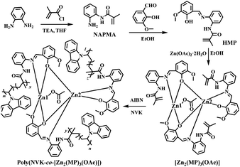
Despite concerted efforts toward monochromatic (blue-,11 green-,12 yellow-,13 orange-14 or red-light15) electroluminescent devices from Zn(II)-complexes, their reliable panchromatic devices (WOLEDs/WPLEDs) greatly underperform. In this regard, benefiting from the volatility of most Zn(II)-complexes, a vacuum-deposition procedure for their WOLEDs was employed. One approach is through the mixing of Zn(II)-complex-based primary colours in a single emitting layer, where the high-energy-state Zn(II)-complex as the host16 and/or sensitizer17 and the low-energy-state complex as the guest18 can be adopted to produce electrically-driven white light with the desired energy transfer between multiple small-molecule chromophores. Another alternative relies on a multilayer structure consisting of two or more separate emitting layers for WOLEDs, where the superposition of a Zn(II)-complex within different primary colours,19 and/or an additional colour-compensation layer by exciplex formation,20 is also capable of white-light modulation. In comparison, multi-layered WOLEDs,19,20 especially those with facilitated carrier-transport abilities, exhibit significantly higher efficiencies (ηc = 1.39–1.65 cd A−1 to 5.2 cd A−1 and ηp up to 1.43 lm W−1) at high luminance (103–104 cd m−2) than those (ηc = 0.12–0.28 cd A−1 and ηp = 0.018–0.082 lm W−1 at 102–103 cd m−2) of single-unit devices.16–18 Nonetheless, besides the inevitable high cost of the vacuum-deposition procedure, unsatisfactory device performance-based crystallization and discrepant components-induced white-light instability pose problems for the two strategies. Convincingly, the circumvention of these problems, to some extent, cannot depend on Zn(II)-based white-light-emitting coordination polymers21 with a lack of inherent processing ability, but can only rely on the doping of Zn(II)-complexes22 and/or sensitizers23 into a polymeric host with a deep LUMO–HOMO bandgap for solution-processable and large-area WPLEDs. The attractive ηc of 14.67 cd A−1, ηp of 6.58 lm W−1 and ηEQE of 6.88% are traded with detrimental deficiency with the inferior CIE (Commission Internationale de l’Eclairage) chromaticity coordinate of (0.42, 0.44) and unstable white light from a phase separation arises during incompatible multi-component integration. As a further solution, a conceptual strategy to use covalent-grafting of a Zn(II)-complex into a polymeric host is considered, where through the molecular dispersion of organo-Zn(II) guests into the colour-compensatory polymer host for high homogeneity, colour-tunable white light should also be realized for the single Zn(II)-complex-grafted polymeric emitter with motivated host-to-guest energy transfer. Herein, based on the copolymerization of NVK with efficient yellow-light tris-vinyl-functionalized complex monomer [Zn2(MP)3(OAc)] for the newly-formed polymer Poly(NVK-co-[Zn2(MP)3(OAc)]) (Scheme 1) with a blue-light PVK support, photo-luminescent colour-tuning to white light after PVK-to-[Zn2(MP)3(OAc)] energy transfer is expected through judicious adjustments of both the grafting concentration and the excitation wavelength. Moreover, desirable WPLEDs fabricated from that single Zn(II)-complex-grafted polymeric emitter are also pursued.
 |
| | Scheme 1 Reaction scheme for the synthesis of the precursor NAPMA, the vinyl-modified Schiff-base ligand HMP, the tris-vinyl-functionalized complex monomer [Zn2(MP)3(OAc)] and the grafting polymer Poly(NVK-co-[Zn2(MP)3(OAc)]). | |
Results and discussion
Synthesis and characterization of the ligand HMP and its complex monomer [Zn2(MP)3(OAc)]
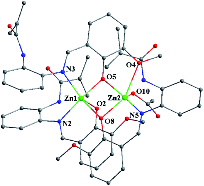
Also as shown in Scheme 1, condensation of the vinyl-modified organic precursor NAPMA with 2-hydroxy-3-methoxy-benzaldehyde gave rise to the vinyl-modified Schiff-base ligand HMP in a yield of 75%. By further treating it with Zn(OAc)2·2H2O, a yellow microcrystalline product of the tris-vinyl-functionalized complex monomer [Zn2(MP)3(OAc)], soluble in common solvents except water, was isolated with a good yield of 60%. HMP and its complex monomer [Zn2(MP)3(OAc)] were well-characterized by elemental analysis, FT-IR, 1H NMR and ESI-MS. Especially in the 1H NMR spectrum (Fig. S1†) of [Zn2(MP)3(OAc)], besides the stipulated proton molar ratio of 3![[thin space (1/6-em)]](https://www.rsc.org/images/entities/char_2009.gif) :1 between the deprotonated (MP)− ligands and the OAc− anion, almost no shifted vinyl-characteristic proton resonances (δ = 5.75 and 5.52 ppm) are observed in comparison with those (δ = 5.77 and 5.53 ppm) of the free HMP ligand, despite the coordination of two Zn2+ ions. The molecular structure of [Zn2(MP)3(OAc)]·EtOH·H2O was determined by X-ray single-crystal diffraction (XRD) analysis with the crystallographic data collected in Tables S1 and S2.†[Zn2(MP)3(OAc)]·EtOH·H2O crystallizes in the monoclinic space group of P2(1)/c, where the structure unit is composed of one neutral molecule [Zn2(MP)3(OAc)], one solvate EtOH and one solvate H2O. As shown in Fig. 1, for the host part, two [Zn(MP)]+ portions with similar N∧O-chelation (N2∧O2 or N5∧O8) modes for each (MP)− ligand are bridged by the third (MP)− ligand with a N∧O∧O-chelation (N3∧O5∧O4) mode, resulting in the formation of a homoleptic binuclear framework. Despite the similar five-coordinate character of each Zn2+ center (Zn1 or Zn2), the distorted square pyramidal geometry of Zn1 consists of one cis-N2O2 core (N2∧O2 and N3∧O5) from two (MP)− ligands as the base plane and one phenoxide-O (O8) from the third (MP)− ligand at the apical position. In contrast, one cis-NO3 core (N5∧O8 and O4∧O5) from two (MP)− ligands as the base plane and the axial occupation by one O atom (O10) from the monodentate OAc− anion contribute to the five-coordinate environment of the other Zn2+ center (Zn2). The two Zn2+ centers (Zn1 and Zn2) are bridged by two phenoxide-O atoms (O5 from the N∧O∧O-chelating (MP)− ligand and O8 from the N∧O-chelating (MP)− ligand), giving a Zn⋯Zn separation of 3.206(2) Å. It is worth noting that each of the terminal methacrylamide groups of the three (MP)− ligands do not participate in the coordination, while their tris-vinyl functionality (1.290(20)–1.357(13) Å of the typical C
:1 between the deprotonated (MP)− ligands and the OAc− anion, almost no shifted vinyl-characteristic proton resonances (δ = 5.75 and 5.52 ppm) are observed in comparison with those (δ = 5.77 and 5.53 ppm) of the free HMP ligand, despite the coordination of two Zn2+ ions. The molecular structure of [Zn2(MP)3(OAc)]·EtOH·H2O was determined by X-ray single-crystal diffraction (XRD) analysis with the crystallographic data collected in Tables S1 and S2.†[Zn2(MP)3(OAc)]·EtOH·H2O crystallizes in the monoclinic space group of P2(1)/c, where the structure unit is composed of one neutral molecule [Zn2(MP)3(OAc)], one solvate EtOH and one solvate H2O. As shown in Fig. 1, for the host part, two [Zn(MP)]+ portions with similar N∧O-chelation (N2∧O2 or N5∧O8) modes for each (MP)− ligand are bridged by the third (MP)− ligand with a N∧O∧O-chelation (N3∧O5∧O4) mode, resulting in the formation of a homoleptic binuclear framework. Despite the similar five-coordinate character of each Zn2+ center (Zn1 or Zn2), the distorted square pyramidal geometry of Zn1 consists of one cis-N2O2 core (N2∧O2 and N3∧O5) from two (MP)− ligands as the base plane and one phenoxide-O (O8) from the third (MP)− ligand at the apical position. In contrast, one cis-NO3 core (N5∧O8 and O4∧O5) from two (MP)− ligands as the base plane and the axial occupation by one O atom (O10) from the monodentate OAc− anion contribute to the five-coordinate environment of the other Zn2+ center (Zn2). The two Zn2+ centers (Zn1 and Zn2) are bridged by two phenoxide-O atoms (O5 from the N∧O∧O-chelating (MP)− ligand and O8 from the N∧O-chelating (MP)− ligand), giving a Zn⋯Zn separation of 3.206(2) Å. It is worth noting that each of the terminal methacrylamide groups of the three (MP)− ligands do not participate in the coordination, while their tris-vinyl functionality (1.290(20)–1.357(13) Å of the typical C![[double bond, length as m-dash]](https://www.rsc.org/images/entities/char_e001.gif) C bond lengths) renders [Zn2(MP)3(OAc)] active in the following copolymerization. Thermogravimetric (TG) analysis (Fig. S2†) of [Zn2(MP)3(OAc)] shows its favourable thermal stability at a decomposition temperature (Td, corresponding to 5% weight loss) up to 290 °C.
C bond lengths) renders [Zn2(MP)3(OAc)] active in the following copolymerization. Thermogravimetric (TG) analysis (Fig. S2†) of [Zn2(MP)3(OAc)] shows its favourable thermal stability at a decomposition temperature (Td, corresponding to 5% weight loss) up to 290 °C.
 |
| | Fig. 1 Schematic of the homoleptic binuclear framework in the tris-vinyl-functionalized complex monomer [Zn2(MP)3(OAc)]·EtOH·H2O. All H atoms and solvates are omitted for clarity. | |
Photophysical property and electronic structure calculation of the complex monomer [Zn2(MP)3(OAc)]
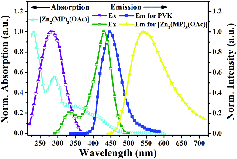
The photophysical property of [Zn2(MP)3(OAc)] was examined in different solutions or in the solid-state at RT or 77 K, and summarized in Table S3†, Fig. 2, S3 and S4.† As shown in Fig. 2, [Zn2(MP)3(OAc)] in MeCN solution at RT shows a distinctively broadened absorption compared to that (Fig. S3†) of the free HMP ligand; the intense absorption bands (λab = 230 and 290 nm) within the high-energy range similar to those present in the free HMP ligand can be assigned to the intraligand π–π* transition, and the other relatively weak bands (λab = 404, 414 and 448 nm) extended to 500 nm should be attributed to a Zn2+-perturbed intraligand π–π* transition. Upon excitation (λex = 397 nm), an intense and broad emission with λem = 538 nm is observed for [Zn2(MP)3(OAc)] in MeCN solution, giving rise to a bright yellow light with CIE chromaticity coordinate x = 0.487 and y = 0.506. The outstanding luminescence property of [Zn2(MP)3(OAc)] is further validated by an attractive quantum efficiency (Φem) of 63%, which is top-level among the reported Zn(II)-complexes.24 The emission at 538 nm for [Zn2(MP)3(OAc)] decays biexponentially with lifetimes of 0.26 and 1.74 ns, indicating that it is characteristic of two Zn(II)-centered species arising from the 1π–π*-based RT fluorescence. By contrast, a distinctively red-shifted emission at 590 nm (also Fig. S3†) for [Zn2(MP)3(OAc)] in MeCN solution at 77 K is observed, and its phosphorescent nature can be further confirmed by the biexponentially time-decayed lifetimes of 0.63 and 2.12 μs. Notably, the RT fluorescence behaviours of [Zn2(MP)3(OAc)] in different solvents show the solvatochromism effect (Fig. S4†), in which, apart from a positive influence on the fluorescence enhancement at the same absorbance value of 397 nm, the 1π–π*-based emission peak is red-shifted from 516–517 nm (toluene, CH2Cl2, THF, EtOAc or CHCl3) to 528 nm (acetone) and to 536–538 nm (MeCN, DMF or MeOH) with increasing polarity of the solvent. Moreover, contributing to the intermolecular interactions, the aggregation-induced bathochromic shift (also Fig. S4†) at 552 nm for [Zn2(MP)3(OAc)] in the solid state relative to that (λem = 538 nm) in MeCN solution at RT is also observed.
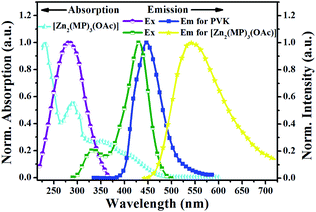 |
| | Fig. 2 Normalized UV-visible absorption and emission spectra for complex monomer [Zn2(MP)3(OAc)] in solution and PVK in the solid-state film at RT. | |
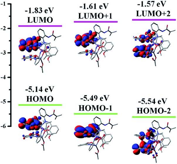
To explore the real origin of the photophysical properties of [Zn2(MP)3(OAc)], time-dependent density functional theory (TD-DFT) calculations based on the optimized S0 geometry were performed, and summarized in Table S4† and Fig. 3. As shown in Fig. 3, the frontier molecular orbitals (FMOs) of the S0 state are primarily dominated by the π orbitals originating from the three coordinated (MP)− ligands, and the contribution from the two Zn2+ ions (dπ) or the coordinated (OAc)− anion appears to be distinctly small. The HOMO and LUMO are mainly (82.76% and 80.59%) localized on the MP1 (N2∧O2-MP)−; from the obvious spatial overlap, the strong optical absorption should correspond to the transition from HOMO to LUMO. However, the LUMO+1 or the LUMO+2 is predominantly (95.44% or 80.21%) located at MP2 (N5∧O8-MP)− or MP3 (N3∧O5∧O4-MP)−, respectively, while the HOMO-1 and HOMO-2 are the dominant combinations (54.25% and 36.30% versus 38.68% and 52.00%) of the MP2 or the MP3. By further checking Table S4,† the calculated S0 → Sn (n = 1–3) transition absorption wavelengths of [Zn2(MP)3(OAc)] are predicted at 450, 416 and 406 nm. For the S0 → S1 transition absorption at 450 nm, a population analysis of HOMO → LUMO (91.06%) and HOMO → LUMO+2 (5.93%) transitions verifies the dominant 1π–π* transition associated with MP1 and the partial ligand-to-ligand charge transfer (LLCT) feature from the π orbitals of MP1 to the π* orbitals of MP3. The calculated absorption peak at 417 nm or 407 nm mainly results from the corresponding HOMO → LUMO+2 (76.36%) or HOMO → LUMO+1 (89.74%) transition, respectively. All the calculated absorptions featuring intraligand 1π–π* transitions are in good agreement with the experimental data (λab = 404, 414 and 448 nm) of [Zn2(MP)3(OAc)] in solution. In order to definitively elucidate its emissive property, natural transition orbitals (NTOs; Table S5 and Fig. S5†) were further obtained from the S0 → T1 excitation with optimized T1 geometry, whereas the prevailing MP1-centered contribution to both particles (96.96%) and holes (95.21%) is also apparent, and thus nearly 100% (99.5%) of hole → particle transitions show that the 3π–π*-dominant transition by the MP1 of [Zn2(MP)3(OAc)] is responsible for its visible phosphorescence. Hence, based on the FMO distribution (also Table S4†) for the T1 state of [Zn2(MP)3(OAc)], the MO shape also favours the emissive LUMO → HOMO (83.56%) transition, and the calculated phosphorescence is located at 593 nm, which is in good agreement with the experimental value of 590 nm (also Fig. S3†) for [Zn2(MP)3(OAc)] in solution at 77 K.
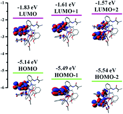 |
| | Fig. 3 The HOMO and LUMO patterns for the complex monomer [Zn2(MP)3(OAc)] based on its optimized S0 geometry. | |
Synthesis, characterization and photophysical property of the grafting-type polymeric film Poly(NVK-co-[Zn2(MP)3(OAc)])
In consideration of the excellent physical properties25 of semi-conducting PVK as a popular matrix, grafting-type polymeric films Poly(NVK-co-[Zn2(MP)3(OAc)]) with different feedings were obtained from the AIBN-initiated copolymerization (also Scheme 1) of NVK and [Zn2(MP)3(OAc)]. As a matter of fact, not only does the blue-light PVK matrix act as colour-compensation for the yellow-light-emissive [Zn2(MP)3(OAc)], it also functions as an effective energy donor with a large absorption cross-section to transfer energy via Förster mechanism26 to the Zn(II)-complex-acceptor. To address the AIBN-initiated radical copolymerization, all the isolated grafting-type polymers Poly(NVK-co-[Zn2(MP)3(OAc)]) were characterized by FT-IR, 1H NMR and GPC methods. On one hand, besides the combined absorption and proton resonances (also Fig. S1†) of the polymerized [Zn2(MP)3(OAc)] and PVK, the absence of the original vinyl-characteristic proton signals of [Zn2(MP)3(OAc)] or NVK also confirms the covalent-grafting27 of [Zn2(MP)3(OAc)] into the PVK backbone. To quantify the actual content of the Zn(II)-complex segment for each polymer, XPS quantitative analyses (Table S6†) reveal that the Zn(II)-complex-grafted concentration is found to be slightly higher than the initial feeding one, which arises from the loss of oligomeric PVK during isolation. Moreover, GPC results (also Table S6†) of their feeding-related Mn values of 17496–82512 g mol−1 with a relatively narrow PDI (polydispersity index) range of 1.13–1.29 should result from the AIBN-initiated radical polymerization. Furthermore, the similarity of the amorphous PXRD pattern (Fig. S6†) of the representative polymer (200:1) to that of PVK also validates the low-concentration homogeneous distribution of the complex monomers in the film-forming PVK matrix. TG and DSC analyses (also Fig. S2†) for the representative polymer Poly(NVK-co-[Zn2(MP)3(OAc)]) (200:1) show distinctively enhanced thermal stability (ca. 410 °C Td, like PVK) over that (290 °C) of [Zn2(MP)3(OAc)], and desirable Tg up to 202 °C.
The photophysical properties of all the polymers Poly(NVK-co-[Zn2(MP)3(OAc)]) (100:1, 200:1, 300:1, 400:1 or 500:1) were investigated in the solid-state film at RT, and summarized in Fig. 4 and S7.† Considering the crossover of the absorption of yellow-light (λem = 538 nm) [Zn2(MP)3(OAc)] with excitation at 345 nm and the excitation at 315 nm of blue-light-emissive (λem = 418 nm) PVK, also shown in Fig. 2, λex = 315–345 nm with 10 nm step-sizes should be used as a suitable excitation regime to realize both their simultaneous emissions and the effective PVK-to-[Zn2(MP)3(OAc)] energy transfer26 for efficient dichromatic-modulated white light.28 Convincingly, the integrated emissions of PVK-based blue light and [Zn2(MP)3(OAc)]-centered yellow light also depend on the feeding adjustment. Under feeding of 100:1, as shown in Fig. S7(a),† photo-excitation with λex = 315–345 nm gives rise to the dominant yellow light (I–A–D; x = 0.396–0.441, y = 0.410–0.458; CCTs = 4553–5337 K and CRIs = 62–66) of [Zn2(MP)3(OAc)]. The deficiency of the PVK-based blue light is due to the effective PVK-to-[Zn2(MP)3(OAc)] energy transfer.26 However, the residual peak emission at 419 nm confirms the allowance of PVK-based blue light after that preferential energy transfer.26 Further decreasing the [Zn2(MP)3(OAc)]-grafted content of the polymer Poly(NVK-co-[Zn2(MP)3(OAc)]) (200:1), the emissive intensity (Fig. 4) of either the PVK-incorporated blue light (λem = 419 nm) or the [Zn2(MP)3(OAc)]-centered yellow light (λem = 540 nm) is also λex-dependent within the whole 315–345 nm range. Through comparing their combinations, all the resultant dichromatic-integration colour-coordinates (II-A–D (x = 0.290–0.323, y = 0.319–0.333)) are located within the desirable white-light regime, covering a broad range of 350–750 nm emissions with CCTs of 8533–9494 K and CRIs of 74–75. The obtained quantum yield of up to 18.4% for the ideal white-light point II-D (x = 0.323, y = 0.333; CCT of 8533 K and CRI of 75) under excitation at 345 nm is the highest among all reported Zn2+-complex-doping systems.22,23 The 2.8 ns lifetime of the PVK-incorporated blue light (λem = 419 nm) and the [Zn2(MP)3(OAc)]-centered yellow light (λem = 540 nm) lifetime of 77 ns confirm that the optimal dichromatic white light should have unambiguous fluorescence characteristics. Interestingly, as for the polymer Poly(NVK-co-[Zn2(MP)3(OAc)]) (300:1), although all the integrated points III-A–D (x = 0.258–0.265, y = 0.296–0.305) also fall into the blue–white-light regime (Fig. S7(b)†), their inferior qualities characteristic of super-cold white light (CCTs = 10790–12099 K) contribute to the relative inefficiency of [Zn2(MP)3(OAc)]-centered yellow light. If more PVK-based blue light is provided for the polymer Poly(NVK-co-[Zn2(MP)3(OAc)]) (400:1 or 500:1), the excess PVK renders the integrated colours (Fig. S7(c and d)†) significantly deviated from the white-light region, exhibiting blue–white (IV-A–D: x = 0.226–0.230, y = 0.229–0.249) and blue light (V-A–D: x = 0.205–0.208, y = 0.180–0.282), respectively. It is worth noting that the [Zn2(MP)3(OAc)]-centered yellow-light species decays with an almost identical lifetime (75–80 ns) to that (77 ns) of Poly(NVK-co-[Zn2(MP)3(OAc)]), which is independent of both the feeding and the excitation wavelength, and should be assigned to the excess amount of PVK with the saturated PVK-to-[Zn2(MP)3(OAc)] energy transfer.26 Moreover, for each of the polymers Poly(NVK-co-[Zn2(MP)3(OAc)]), the facilitated separation of [Zn2(MP)3(OAc)] chromophores within the PVK backbone to avoid unexpected self-quenching29 also occurs upon low-concentration grafting. With the aim of knowing the distribution of [Zn2(MP)3(OAc)] chromophores within the PVK backbone, AFM images of the polymeric films (40 nm) Poly(NVK-co-[Zn2(MP)3(OAc)]) obtained by spin-coating on ITO glass slides were investigated. As shown in Fig. S8,† all the polymeric films with different grafting contents (100:1–500:1) show smooth surfaces with a low root-mean-square (RMS) roughness less than 1.7 nm (1.684 nm (100:1); 1.031 nm (200:1); 1.022 nm (300:1); 1.018 nm (400:1); 1.013 nm (500:1)), which is also indicative of their homogeneous nature without guest aggregation.29 Meanwhile, due to the smooth surface and the stipulated Zn(II)-grafting content reflected in the SEM-EDS analysis (Fig. S9†), it seems that the representative polymer film Poly(NVK-co-[Zn2(MP)3(OAc)]) (200:1) possesses qualities desirable for high-performance devices.
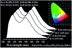 |
| | Fig. 4 Normalized emission spectra and corresponding CIE chromatic coordinates (inset) of the polymeric film Poly(NVK-co-[Zn2(MP)3(OAc)]) (200:1) upon excitation (λex = 315–345 nm) at RT. | |
Device performance of WPLEDs-I–II based on the polymeric film Poly(NVK-co-[Zn2(MP)3(OAc)]) (200![[thin space (1/6-em)]](https://www.rsc.org/images/entities/h3_char_2009.gif) :1)
:1)
Considering the straightforward and highly efficient white light of the polymeric film Poly(NVK-co-[Zn2(MP)3(OAc)]) (200:1), its prototype WPLED-I configured with ITO/PEDOT:PSS (40 nm)/Poly(NVK-co-[Zn2(MP)3(OAc)]) (200:1; 40 nm)/TPBi (30 nm)/LiF (1 nm)/Al (100 nm) (Fig. 5(a)) was fabricated using a simple solution-processing technique. The CV result (Fig. S10†) of Poly(NVK-co-[Zn2(MP)3(OAc)]) (200:1) shows its electrochemical HOMO and LUMO levels of −2.69 and −5.21 eV, respectively. PEDOT:PSS (poly(3,4-ethylenedioxythiophene):poly(styrenesulfonate)) acts as the hole-injecting material, and TPBi (1,3,5-tris(2-N-phenylbenzimidazolyl)benzene) was adopted to facilitate the electron-transport. Due to the critical matching of both the LUMO (−2.69 eV) and HOMO (−5.21 eV) levels of the polymer with the LUMO level (−2.70 eV) of TPBi and the HOMO (−5.20 eV) of PEDOT:PSS, respectively, the injected electrons and holes can effectively be recombined within the polymer, and subsequently carrier-trapping and colour-compensation should occur. Just as expected, WPLED-I gives simultaneous emissions (Fig. 5(b)) of PVK-based blue light (λem = 420 nm) and [Zn2(MP)3(OAc)]-centered yellow light (λem = 540 nm) throughout the whole applied bias voltage range (7.0–18.0 V; Fig. 5(c)). Moreover, after the turn-on voltage (Von at 1 cd m−2) of 7.0 V, their comparative combination exhibits stable white light (CIE coordinates of x = 0.297–0.300, y = 0.332–0.339; CCTs of 7105–7346 K and CRIs of 81–82) within the 7.0–12.0 V range. As shown in Fig. 5(f), with an increase in the applied bias voltage, both the luminance (L, cd m−2) and the current density (J, mA cm−2) monotonously increase, and LMax = 44.2 cd m−2 is achieved at 12.0 V with a current density of 9.8 mA cm−2. Under the stable premise (7.0–12.0 V) for the WPLED-I, with an increase in luminance or applied bias voltage, as shown in Fig. 5(g), all the efficiencies (ηc, ηp and ηEQE) instantly decrease with ηMaxc = 2.2 cd A−1, ηMaxp = 1.0 lm W−1 and ηMaxEQE = 1.7%. To our dismay, upon using an applied bias voltage up to 12.0 V, both the ηc and ηp efficiencies decrease to 0.5 cd A−1 and 0.15 lm W−1, respectively, and severe (ca. 73%) efficiency roll-off (ηEQE = 0.45%) also takes place. Especially when the applied bias voltage is further increased (>12.0 V), the significantly inferior performance caused by the carrier imbalance30 should be attributed to the ageing of the WPLED-I.
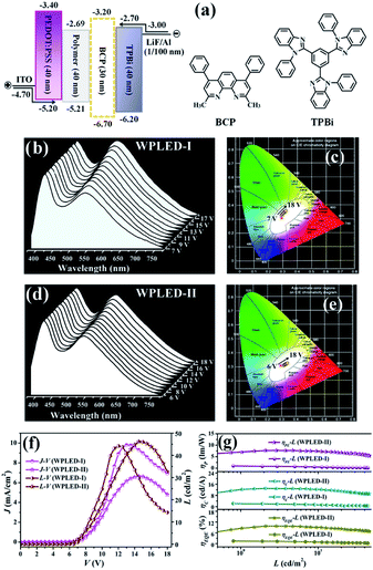 |
| | Fig. 5 (a) Device structures for the WPLED-I–II with energy level diagrams; (b) electroluminescence spectra and (c) CIE chromaticity coordinates for the WPLED-I; (d) electroluminescence spectra and (e) CIE chromaticity coordinates for the WPLED-II; (f) J–V–L and (g) ηc–L, ηp–L and ηEQE–L for the WPLED-I–II. | |
Based on optimization with the additional BCP layer for carrier blocking,31 the BCP-incorporated (30 nm) WPLED-II was fabricated. Convincingly, because charge carriers can be confined within the broadened recombination zone, the WPLED-II exhibits improved electroluminescence properties as desired. First, besides a lower Von of 6.0 V, the dichromatic white light (Fig. 5(d and e); CIE coordinates of x = 0.325–0.329, y = 0.300–0.310; CCTs of 7050–7318 K and CRIs of 82–84) can be stable within an extended applied bias voltage range of 6.0–15.0 V, and LMax (46.2 cd m−2) is slightly increased with a lower J of 6.7 mA cm−2 at 15.0 V. More importantly, its maximum efficiencies (ηMaxc = 13.0 cd A−1, ηMaxp = 6.1 lm W−1 and ηMaxEQE = 9.2%) reformed almost 5–6 times more than those of the WPLED-I and are the best (Table S7†) among reported Zn(II)-complex-based WOLEDs16–20/WPLEDs,22,23 to our knowledge. Furthermore, within the stable illuminating range, the high efficiencies (ηc = 9.1 cd A−1, ηp = 4.4 lm W−1 and ηEQE = 6.8%) are maintained, with distinctively weaker efficiency roll-off (ca. 25%) than that (ca. 73%) of the WPLED-I. The WPLED-II is distinctively superior to the ubiquitous WOLEDs/WPLEDs (>40%) based on Ir(III)-5 or Pt(II)-complexes6 with large phosphorescence-decayed lifetimes. Inspiringly, the record-high performance (high efficiencies and weak efficiency roll-off) of the WPLED-II renders the single Zn(II)-complex-grafted polymer a new platform for cost-effective and large-area flexible WPLEDs, and could be further improved through material modification and device optimization.
Conclusions
In summary, for the first time, tris-vinyl-functionalized yellow-light complex monomer [Zn2(MP)3(OAc)] was copolymerized with NVK to obtain the single grafted-type polymers Poly(NVK-co-[Zn2(MP)3(OAc)]) for WPLEDs. Especially, using Poly(NVK-co-[Zn2(MP)3(OAc)]) (200:1) with straightforward white light as the emitting layer, a reliable WPLED-II with optimized carrier balance gives record-high device performance (both high efficiencies (13.0 cd A−1 of ηMaxc, 6.1 lm W−1 of ηMaxp and 9.2% of ηMaxEQE) and weak (ca. 25%) efficiency roll-off) compared with previous organo-Zn2+-based WOLEDs/WPLEDs. This outstanding result renders the single Zn(II)-complex-grafting polymer a new platform for cost-effective and large-area flexible WPLEDs for potential full-colour flat displays.
Conflicts of interest
There are no conflicts to declare.
Acknowledgements
Prof. X. Q. Lü thanks the National Natural Science Foundation (21373160, 21173165), the Program for New Century Excellent Talents in University from the Ministry of Education of China (NCET-10-0936), the State Key Laboratory of Structure Chemistry, and the Wisteria Scientific Research Cooperation Special Project of Northwest University in P. R. of China for the support of this work. Prof. H. S. He thanks the National Science Foundation (1507871) in the United States for the support of this work. Prof. L. Liu thanks the National Natural Science Foundation of China (21671061) and the Application Foundation Frontier Special Project by Wuhan Science and Technology Bureau (2019010701011414) for the support of this work. Prof. W.-Y. Wong thanks the Hong Kong Research Grants Council (PolyU153062/18P), the Hong Kong Polytechnic University (1-ZE1C) and the Endowed Professorship in Energy from Ms. Clarea Au (847S) for the financial support.
Notes and references
- J. Kido, M. Kimura and K. Nagai, Science, 1995, 267, 1332–1334 CrossRef CAS PubMed.
-
(a) H. Sasabe and J. Kido, J. Mater. Chem. C, 2013, 1, 1699–1707 RSC;
(b) R. Sebastian, T. Michael, L. Bjoern and L. Karl, Rev. Mod. Phys., 2013, 85, 1245–1293 CrossRef.
-
(a) B. Q. Liu, X. L. Li, H. Tao, J. H. Zou, M. Xu, L. Wang, J. B. Peng and Y. Cao, J. Mater. Chem. C, 2017, 5, 7668–7683 RSC;
(b) J. S. Chen, F. C. Zhao and D. G. Ma, Mater. Today, 2014, 17, 175–183 CrossRef CAS;
(c) L. L. Bao and M. D. Heagy, Curr. Org. Chem., 2014, 18, 740–772 CrossRef CAS;
(d) G. M. Farinola and R. Ragni, Chem. Soc. Rev., 2011, 40, 3467–3482 RSC;
(e) Q. Wang and D. G. Ma, Chem. Soc. Rev., 2010, 39, 2387–2398 RSC;
(f) K. T. Kamtekar, A. P. Tonkman and M. R. Bryce, Adv. Mater., 2010, 22, 572–582 CrossRef CAS PubMed.
-
(a) L. Ying, C.-L. Ho, H. B. Wu, Y. Cao and W.-Y. Wong, Adv. Mater., 2014, 26, 2459–2473 CrossRef CAS PubMed;
(b) C. Tang, X. D. Liu, F. Liu, X. L. Wang, H. Xu and W. Huang, Macromol. Chem. Phys., 2013, 214, 314–342 CrossRef CAS;
(c) H. B. Wu, L. Ying, W. Yang and Y. Cao, Chem. Soc. Rev., 2009, 38, 3391–3400 RSC.
-
(a) T. Y. Li, J. Wu, Z. G. Wu, Y. X. Zheng, J. L. Zuo and Y. Pan, Coord. Chem. Rev., 2018, 374, 55–92 CrossRef CAS;
(b) C. Ulbricht, B. Beyer, C. Friebe, A. Winter and U. S. Schubert, Adv. Mater., 2009, 21, 4418–4441 CrossRef CAS.
-
(a) C.-L. Ho and W.-Y. Wong, Top. Curr. Chem., 2016, 374, 1 CrossRef CAS PubMed;
(b) G. J. Zhou, W.-Y. Wong and X. L. Yang, Chem.–Asian J., 2011, 6, 1706–1727 CrossRef CAS PubMed.
- L. X. Xiao, Z. J. Chen, B. Qu, J. X. Luo, S. Kong, Q. H. Gong and J. Kido, Adv. Mater., 2011, 23, 926–952 CrossRef CAS.
-
(a) C. Bizzarri, E. Spuling, D. M. Knoll, D. Volz and S. Braese, Coord. Chem. Rev., 2018, 373, 49–82 CrossRef CAS;
(b) C. Groves, Nat. Mater., 2013, 12, 597–598 CrossRef CAS PubMed.
- G. M. Farinola and R. Ragni, Chem. Soc. Rev., 2011, 40, 3467–3482 RSC.
- G. J. Zhou, W.-Y. Wong and S. Suo, J. Photochem. Photobiol., C, 2010, 11, 133–156 CrossRef CAS.
-
(a) H.-J. Son, W.-S. Han, J.-Y. Chun, B.-K. Kang, S.-N. Kwon, J. Ko, S. J. Han, C. Lee, S. J. Kim and S. O. Kang, Inorg. Chem., 2008, 47, 5666–5676 CrossRef CAS;
(b) T. Z. Yu, W. M. Su, W. L. Li, Z. R. Huo, R. N. Hua, M. T. Li, B. Chu, B. Li, Z. Q. Zhang and Z. Z. Hu, Inorg. Chim. Acta, 2006, 359, 2246–2251 CrossRef CAS.
-
(a) V. Nishal, D. Singh, A. Kumar, V. Tanwar, I. Singh, R. Srivastava and P. S. Kadyan, J. Org. Semicond., 2014, 2, 15–20 CrossRef;
(b) H. Xu, Z. F. Xu, Z. Y. Yue, P. F. Yan, B. Wang, L. W. Jia, G. M. Li, W. B. Sun and J. W. Zhang, J. Phys. Chem. C, 2008, 112, 15517–15525 CrossRef CAS;
(c) G. Yu, S. W. Yin, Z. G. Shuai and D. B. Zhu, J. Am. Chem. Soc., 2003, 125, 14816–14824 CrossRef CAS PubMed.
-
(a) A. Kumar, R. Srivastava, A. Kumar, V. Nishal, P. S. Kadyan, M. N. Kamalasanan and I. Singh, J. Organomet. Chem., 2013, 740, 116–122 CrossRef CAS;
(b) R. J. Wang, L. J. Deng, M. Fu, J. L. Cheng and J. Y. Li, J. Mater. Chem., 2012, 22, 23454–23460 RSC;
(c) Y. Sakai, Y. Sagara, H. Nomura, N. Nakamura, Y. Suzuki, H. Miyazaki and C. Adachi, Chem. Commun., 2015, 51, 3181–3184 RSC.
-
(a) A. Kumar, A. K. Palai, R. Srivastava, P. S. Kadyan, M. N. Kamalasanan and I. Singh, J. Organomet. Chem., 2014, 756, 38–46 CrossRef CAS;
(b) X. J. Xu, Y. Liao, G. Yu, H. You, C. A. Di, Z. M. Su, D. G. Ma, Q. Wang, S. Y. Li, S. Q. Wang, J. P. Ye and Y. Q. Liu, Chem. Mater., 2007, 19, 1740–1748 CrossRef CAS.
-
(a) H. Kanno, K. Ishikawa, Y. Nishio, A. Endo, C. Adachi and K. Shibata, Appl. Phys. Lett., 2007, 90, 123509 CrossRef;
(b) P. F. Wang, Z. R. Hong, Z. Y. Xie, S. W. Tong, O. Y. Wang, C.-S. Lee, N. B. Wong, L. S. Hung and S. Lee, Chem. Commun., 2003, 1664–1665 RSC.
-
(a) V. K. Rai, R. Srivastava and M. N. Kamalasanan, Synth. Met., 2009, 159, 234–237 CrossRef CAS;
(b) X. M. Wu, Y. L. Hua, Z. Q. Wang, J. J. Zheng, S. G. Yin, J. C. Deng, K. W. Wu, S. Liu, F. J. Zhu and X. Niu, Optik, 2006, 117, 373–376 CrossRef CAS.
- V. K. Rai, R. Srivastava and M. N. Kamalasnan, J. Lumin., 2010, 130, 249–253 CrossRef CAS.
-
(a) P. Tyagi, R. Srivastava, A. Kumar, V. K. Rai, R. Grover and M. N. Kamalasanan, Synth. Met., 2010, 160, 756–761 CrossRef CAS;
(b) Y.-K. Jang, D.-E. Kim, W.-S. Kim, B.-S. Kim, O.-K. Kwon, B.-J. Lee and Y.-S. Kwon, Thin Solid Films, 2007, 515, 5075–5078 CrossRef CAS.
-
(a) D.-E. Kim, Y.-S. Kwon and H.-K. Shin, J. Nanosci. Nanotechnol., 2015, 15, 488–491 CrossRef CAS;
(b) G. Y. Ding, W. L. Jiang, J. Wang, L. Z. Wang, G. D. Wang, L. Cong, X. H. Ouyang and H. P. Zeng, Semicond. Sci. Technol., 2009, 24, 025016 CrossRef;
(c) D.-E. Kim, W.-S. Kim, B.-S. Kim, B.-J. Lee and Y.-S. Kwon, Thin Solid Films, 2008, 516, 3637–3640 CrossRef CAS;
(d) D.-E. Kim, W.-S. Kim, B.-S. Kim, B.-J. Lee and Y.-S. Kwon, Colloids Surf., A, 2008, 313–314, 320–323 CrossRef;
(e) D.-E. Kim, W.-S. Kim, B.-J. Lee and Y.-S. Kwon, Jpn. J. Appl. Phys., 2007, 46, 2749–2752 CrossRef CAS;
(f) Y. Hamada, T. Sano, H. Fujii, Y. Nishio, H. Takahashi and K. Shibata, Jpn. J. Appl. Phys., 1996, 35, L1339–L1341 CrossRef CAS.
-
(a) F. Dumur, L. Beouch, M.-A. Tehfe, E. Contal, M. Lepeltier, G. Wantz, B. Graff, F. Goubard, C. R. Mater, J. Lalevée and D. Gigmes, Thin Solid Films, 2014, 564, 351–360 CrossRef CAS;
(b) H. X. Xu, Y. Yue, H. Wang, L. Q. Chen, Y. Y. Hao and B. S. Xu, J. Lumin., 2012, 132, 919–923 CrossRef CAS;
(c) Y. H. Hao, W. X. Meng, H. X. Xu, H. Wang, X. G. Liu and B. S. Xu, Org. Electron., 2011, 12, 136–142 CrossRef CAS;
(d) F. J. Zhu, Y. L. Hua, S. G. Yin, J. C. Deng, K. W. Wu, X. Niu, X. M. Wu and M. C. Petty, J. Lumin., 2007, 122–123, 717–719 CrossRef CAS;
(e) S. P. Singh, Y. N. Mohapatra, M. Qureshi and S. S. Manoharan, Appl. Phys. Lett., 2005, 86, 113505 CrossRef.
-
(a) C. Wang, Z. Yin, W. M. Ma, X. Y. Li, L. H. Cao, Y. Cheng, X. Y. Yu and Y. M. Ma, Dalton Trans., 2019, 48, 14966–14970 RSC;
(b) X. G. Yang and D. P. Yan, Chem. Commun., 2017, 53, 1801–1804 RSC;
(c) L. Chen, C. Yan, M. Pan, H. P. Wang, Y. N. Fan and C. Y. Su, Eur. J. Inorg. Chem., 2016, 2676–2680 CrossRef CAS.
-
(a) J. C. Germino, J. N. de Freitas, R. A. Domingues, F. J. Quites, M. M. Faleiros and T. D. Z. Atvars, Synth. Met., 2018, 241, 7–16 CrossRef CAS;
(b) M. Cibian, A. Shahalizad, F. Souissi, J. Castro, J. G. Ferreira, D. Chartrand, J.-M. Nunzi and G. S. Hanan, Eur. J. Inorg. Chem., 2018, 4322–4330 CrossRef CAS.
- G. Cheng, G. K.-M. So, W.-P. To, Y. Chen, C.-C. Kwok, C. S. Ma, X. G. Guan, X. Y. Chang, W.-M. Kwok and C.-M. Che, Chem. Sci., 2015, 6, 4623–4635 RSC.
- D. Frederic, Synth. Met., 2014, 195, 241–251 CrossRef.
- J. Liu and Q. B. Pei, Curr. Org. Chem., 2010, 14, 2133–2144 CrossRef CAS.
- K. E. Sapsford, L. Berti and I. L. Medintz, Angew. Chem., Int. Ed., 2006, 45, 4562–4588 CrossRef CAS PubMed.
-
(a) G. R. Fu, J. Q. Guan, B. N. Li, L. Liu, Y. N. He, C. Yu, Z. Zhang and X. Q. Lü, J. Mater. Chem. C, 2018, 6, 4114–4121 RSC;
(b) L. Liu, M. Y. Pang, H. T. Chen, G. R. Fu, B. N. Li, X. Q. Lü and L. Wang, J. Mater. Chem. C, 2017, 5, 9021–9027 RSC;
(c) Z. Zhang, Y. N. He, L. Liu, X. Q. Lü, X. J. Zhu, W.-K. Wong, M. Pan and C. Y. Su, Chem. Commun., 2016, 52, 3713–3716 RSC.
-
(a) M. M. Shang, C. X. Li and J. Lin, Chem. Soc. Rev., 2014, 43, 1372–1386 RSC;
(b) M. Pan, W. M. Liao, S. Y. Yin, S. S. Sun and C. Y. Su, Chem. Rev., 2018, 118, 8889–8935 CrossRef CAS PubMed.
- S. Farhangi and J. Duhamel, Macromolecules, 2016, 49, 6149–6162 CrossRef CAS.
- C. Murawski, K. Leo and M. C. Gather, Adv. Mater., 2013, 25, 6801–6827 CrossRef CAS.
- X. L. Yang, G. J. Zhou and W.-Y. Wong, J. Mater. Chem. C, 2014, 2, 1760–1778 RSC.
Footnotes |
| † Electronic supplementary information (ESI) available: Starting materials and characterization methods; detailed synthesis and characterization; XRD; quantum calculations. CCDC 1894830. For ESI and crystallographic data in CIF or other electronic format see DOI: 10.1039/c9sc05288g |
| ‡ These authors contributed equally and should be considered co-first authors. |
|
| This journal is © The Royal Society of Chemistry 2020 |

 Open Access Article
 This Open Access Article is licensed under a Creative Commons Attribution-Non Commercial 3.0 Unported Licence
 *a,
Hongshan
He
*a,
Hongshan
He