
 Open Access Article
 This Open Access Article is licensed under a
 Creative Commons Attribution 3.0 Unported Licence
Beyond electrolysis: old challenges and new concepts of electricity-driven chemical reactors
Andrzej I.
Stankiewicz
 *ab and
Hakan
Nigar
a
*ab and
Hakan
Nigar
a
aProcess and Energy Department, Delft University of Technology, Leeghwaterstraat 39, 2628 CB Delft, The Netherlands. E-mail: a.i.stankiewicz@tudelft.nl
bFaculty of Chemical and Process Engineering, Warsaw University of Technology, Waryńskiego 1, 00-645 Warsaw, Poland
First published on 21st April 2020
Abstract
With renewable electricity becoming the most widespread, flexible, and accessible form of energy on Earth, electrification of chemical processes presents one of the most promising transition paths to low-carbon-footprint, environmentally-neutral manufacturing of fuels and chemicals. The current paper provides a critical perspective on the entire spectrum of chemical and catalytic reactors, in which electricity plays different roles targeting either the reaction mechanism or the thermal energy supply. Related challenges and necessary developments to address those challenges are discussed.
Introduction
Decarbonization of the energy-intensive manufacturing industries presents one of the most urgent technological challenges of coming decennia. Among those industries, the chemical sector (including refineries) is by far the most significant energy consumer – according to the U.S. Energy Information Administration, in 2018, the bulk chemical and refining sectors were responsible for 46% of the entire energy consumption by the American industry.1 The transition scenarios to the low-carbon energy in the chemical process industries are commonly based on the so-called power-to-X concept, which basically assumes using low-carbon or renewable electricity to produce fuels and/or chemicals.2–7 However, in the vast majority of rich research literature related to those scenarios, the use of electricity is limited to the initial steps of electro(cata)lytic conversion of water, CO2 and/or nitrogen, respectively to hydrogen, carbon monoxide, syngas, formic acid, methanol or ammonia.8–20 The subsequent reaction steps are usually assumed to be carried out in the conventional, thermochemical way. While the electrocatalytic production of fuels from water, CO2 or nitrogen is undoubtedly of fundamental importance for decarbonizing (or rather defossilizing) the chemical sector, it is equally important to address possible applications of electricity in the reactions further down the chain – the reactions that eventually lead to thousands of chemical products on the market today. With those reactions in mind, in the current paper we critically review the entire spectrum of relevant electricity-based chemical and catalytic reactors, focusing on the related challenges and the new concepts to address them.Electricity roles in chemical and catalytic reactors
Generally speaking, electricity can be applied in a chemical reactor, either directly or indirectly. The latter means that the reactor utilizes another energy form, to which electricity is first converted, e.g., microwave, light, etc. In either of the above, electricity can fulfil two distinct roles in a chemical reactor. On the one hand, it can target the reaction mechanism, usually switching it from the thermal to the non-thermal one, based on the electron/charge transfer. On the other hand, electricity can be used as a means for fast (and in some cases selective) energy supply to the thermally-driven reactions (Fig. 1).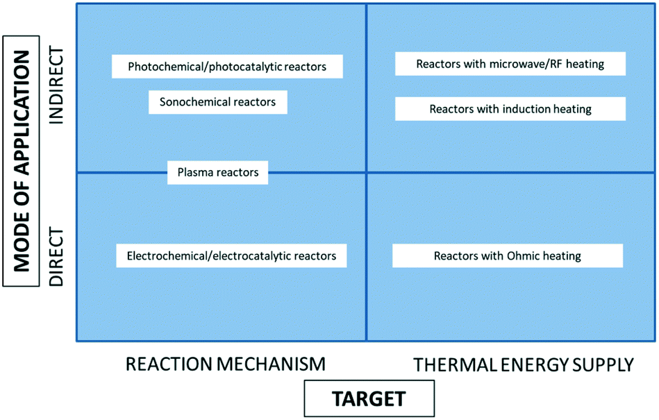 | ||
| Fig. 1 Classification of the electricity-based reactors with respect to the mode of electricity application and its role in the reactor. | ||
Reactors belonging to the first category include:
• Electrochemical and electrocatalytic reactors, in which electric current (DC) is supplied directly to the electrodes causing charge transfer across the interface between the electrode and the processed liquid.
• Photochemical and photocatalytic reactors, in which electrical energy is converted to a mono- or polychromatic light, and the emitted photons produce either direct excitation of the reacting molecules or creation of the electron–hole pairs in the catalyst.
• Plasma reactors, in which electricity is used (directly or indirectly) to create highly reactive plasmas with a large number of chemically active species, such as electrons, ions, atoms, and radicals.
• Sonochemical reactors, in which electricity converted to ultrasound creates microcavitation and generates free radicals in the reacting liquid.
Thermal energy transfer in electricity-based reactors can be realized via:
• Microwave/RF heating, in which the rapidly alternating electric field of the microwave generates heat by moving dipolar molecules or ions in liquids, or by getting absorbed in the so-called “dielectric lossy” solid non-magnetic materials.
• Ohmic or Joule heating, in which the electric current passing through a resistive conductor produces heat.
• Induction heating, in which the rapidly alternating magnetic field either generates eddy currents in conducting materials resulting in the Joule heating of those materials, or generates heat in ferro-/ferrimagnetic materials by the magnetic hysteresis losses.
Applications, challenges and new concepts of electricity-driven reactors
Systems targeting reaction mechanism
Despite their long history and commercial successes, the design and scale-up of electrochemical reactors remain complex and challenging tasks, in which various elements address diverse general and application-specific design issues. Those essential elements of electrochemical reactor design are summarized in Table 1.
| Design element | Issue/challenge addressed | Ref. |
|---|---|---|
| Reactor type/geometry | High electrode area per unit volume; high current density; low voltage; heat management; hydrodynamics | 22–24 |
| Electrode geometry and material | Uniform potential/current distribution; low voltage; electrode durability | 25 and 26 |
| Electrocatalyst | High reaction rate/selectivity; low overpotential | 27–29 |
| Electrode surface structure | Improved mass transfer | 30–32 |
| Diaphragm/membrane | High selectivity; improved product separation; reduced mixing of electrolytes and (gaseous) reaction products | 22, 23 and 33–35 |
| Reduced energy losses | ||
| Electrolyte | Improved stability; high ionic conductivity; improved mass transfer | 36 |
A great variety of electrochemical reactor concepts have been developed and implemented in industrial practice.22 The more traditional include parallel-plate reactors, rotating-electrode reactors, “Swiss-roll-cell” reactors, as well as reactors with packed-bed or fluidized-bed electrodes.23 More recently, BASF37 presented a reactor for electrosynthesis of aromatic aldehydes, based on the “capillary gap” cell (Fig. 2a). The cell is constructed of a stack of bipolar round graphite electrodes with a central hole, separated by spacers. The electrolyte flows via the central channel created by the stacking and then outwards between the electrodes. Such a reactor design results in a high ratio of electrode surface area to reactor volume.
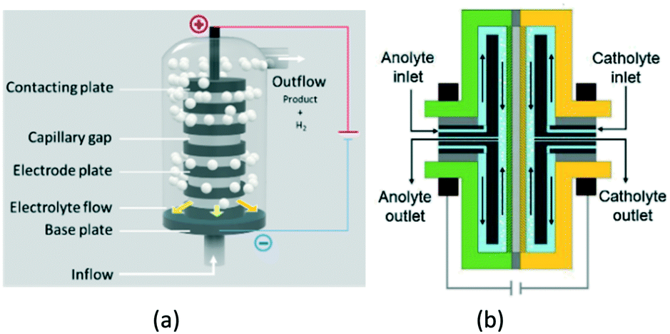 | ||
| Fig. 2 Capillary gap cell (a) and rotor–stator spinning disc membrane electrochemical reactor (b). Fig. 2b reprinted from Granados Mendoza, et al.,39 with permission from Elsevier. | ||
Somewhat similar in terms of the basic idea is the electrochemical pump cell based on rotating disc-type electrodes, that dates back to mid-1970s.38 It has recently been further developed as the spinning disc membrane electrochemical reactors39 (Fig. 2b). Here, the electrolytes are fed through the central channel and flow in the gap between the rotating electrode and the stator.
The most recent trend is the development of microfluidic flow devices for electrochemical synthesis.40–42 Those devices overcome many traditional limitations associated with electrochemistry and can operate in serial or parallel mode (numbering-up). However, tiny volumes (below 1 mL) restrict their possible use for commercial-scale manufacturing.
Generally speaking, the use of light to activate chemical bonds may render two critical advantages compared to the traditional thermochemical processes:
• Process selectivity to the required products can drastically increase, due to the different chemistry, or low/ambient process temperature.
• The energy consumption in the process can radically decrease, due to the low-temperature processing.
However, in order to maximize the above advantages, important challenges related to quantum yield, light attenuation (Beer–Lambert law), and overall energy efficiency need to be resolved via the light source and reactor design.
A variety of light sources can be used in photochemistry,45 with mercury lamps being still the most common solution in large-scale applications. The main features of the most relevant light sources used or studied in photochemical reactors are presented in Table 2.
| Light source | Wave lengths (approx.) | Radiant efficiency (approx.) | Lifetime till 70% intensity [h] (approx.) | Remarks |
|---|---|---|---|---|
| Mercury lamp | 200–600 nm | 0.32 | 2000–10![[thin space (1/6-em)]](https://www.rsc.org/images/entities/char_2009.gif) 000 000 |
Polychromatic |
| Xenon lamp | 200–2500 nm | 0.80 | 2000 | Polychromatic |
| Excimer lamp | 108–350 nm; (most often 172 nm) | 0.25–0.40 | 2000 | Quasi monochromatic |
| Fluorescent black light | 310–450 nm | 0.25 | 20000 |
Polychromatic |
| LED | 210–900 nm | 0.01–0.62 | 20000 |
Quasi monochromatic |
| Laser | 193–10600 |
0.25 | Up to 70000 (time to failure) |
True monochromatic |
The choice of the photoreactor type depends on different factors, including the phases present, the required production capacity, the reaction chemistry, and the physical properties of the reactants/solvents. The primary challenge in the reactor design is the efficiency of the photon transfer from the light source to target molecules or photocatalysts. In liquid-phase processes, immersion reactors are the most popular. A classic example here is the pool reactor for photo-oximation of cyclohexane (see earlier), in which a multitude of immersed mercury lamps are used. The mercury lamps generate large quantities of heat and are polychromatic. Therefore, they require filters and intensive cooling systems.
Much more efficient, in particular on the small-to-medium production scales, are continuous-flow photoreactors.46–49 These reactors are commonly constructed of transparent plates with specially shaped micro- or millichannels and LED-matrices as the light sources. A typical representative of this category is the G3 Photo Reactor developed at Corning (Fig. 3). The reactor, made of glass, PFA, and perfluoroelastomer, has the maximum processing capacity of 2 l min−1. It uses monochromatic LED irradiation and provides efficient light penetration with both sides of fluidic modules illuminated. Efficient liquid cooling extends the LEDs lifetime. Corning claims the reactor to offer 1000 times better heat transfer, 100 times better mass transfer, 1000 times lower volume, and 50 times better residence time distribution than the batch reactor. Next to the G3 model, there are several other flow-chemistry photoreactors on the market, e.g., PhotoCube™ (ThalesNano, Hungary) or PhotoSyn™ (Uniqsis, UK). Those reactors, however, have lower processing capacities and therefore are more suited for laboratory-scale applications.
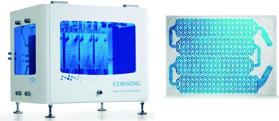 | ||
| Fig. 3 Corning® Advanced-Flow™ G3 photo reactor (left) and G3 fluidic module (right). © 2018 and 2017 Corning Incorporated. All rights reserved. Reprinted with permission. | ||
Recently, a continuous-flow stirred-tank photoreactor with a fiber-coupled, high-powered diode laser as the light source has been investigated.50 The reactor utilizes an adjustable beam expander to ensure uniform illumination of the liquid surface (Fig. 4). Running a C–N coupling reaction, the lab-scale device with only 100 ml volume has been able to operate at a throughput of 1.2 kg per day, which proves its potential for application in small-scale pharmaceutical manufacturing.
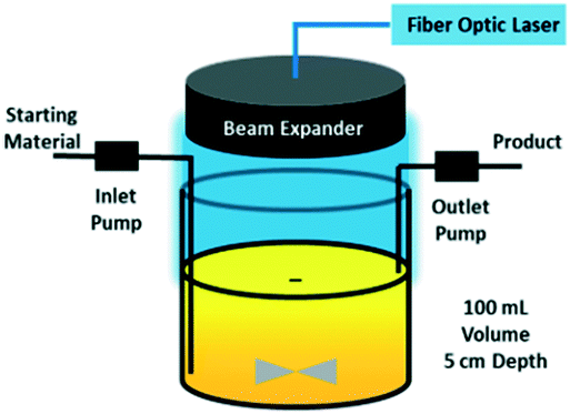 | ||
| Fig. 4 Continuous stirred-tank photo reactor with fiber-coupled laser diode as the light source. Reprinted from Harper et al.,50 with permission from ACS. | ||
Additional challenges and design concepts are encountered in the photocatalytic processes running on solid photocatalysts. Here, not only the optimum positioning of the light source with respect to the catalyst surface but also the catalyst deposition on illuminated reactor elements, the specific illuminated surface area as well as general scalability of the device, play an essential role. A good overview of various photocatalytic reactor concepts that include flat plate, slurry, spinning disc, honeycomb monolithic, optical fiber, annular, packed-bed, fluidized-bed, and microreactors, can be found in Van Gerven et al.51 and Khodadadian et al.52
A common hurdle in photocatalytic reactors is their limited energetic efficiency. This is due on the one hand to the light absorption and dissipation between the source and the catalytic site, and on the other hand to the “mismatch” between the large bandgap of the photocatalyst (usually TiO2) and the visible light source, resulting in effective utilization of only a small UV-part of the emitted light. The ultimate solution to the light absorption/dissipation problem would be to generate the light directly in the catalyst or the solvent containing the reactants (“nano-illumination”). So far, that topic has attracted only limited attention. Gole et al.53 proposed the introduction of nitrogen-doped titania nanostructures into the pores of porous silicon (PS) in order to develop a device generating visible light by electroluminescence of PS, thus activating the photocatalyst particles. This device could then be incorporated in a micro- or millireactor, as shown in Fig. 5. Another example of nanoscale illumination is the use of phosphorescent solids, which are irradiated prior to their injection in the reactant stream.54 Much more abundant is the literature concerning the improvement (reduction) of the bandgap of the photocatalysts, where significant developments in the field of plasmonic catalysts are seen.55–57
 | ||
| Fig. 5 Nanoscale illumination reactor. Source: Van Gerven et al.;51 reprinted with permission from Elsevier. | ||
Last but not least, the use of light and photocatalysts in photoelectrochemical cells needs to be mentioned. Those cells are composed of a transparent anode coated with a nanostructured photocatalyst and a conventional cathode. Illumination of the anode generates electrons in the photocatalyst, which are then conducted via an external circuit to the cathode and carry out reduction reactions there. In contrast, the generated holes in the photoanode are used for carrying out oxidation reactions. Among potential applications of photoelectrochemical reactors, the production of hydrogen dominates the field.58–61
The three basic challenges on the way to more industrial-scale applications of electricity-driven reactors, i.e. (i) energy efficiency, (ii) reaction selectivity/yield control, and (iii) reactor scale-up, are particularly pronounced in case of plasma reactors. Among all types of plasma, the microwave-induced plasma has the highest energy efficiency when operated under reduced pressure (∼100–200 Torr) but that efficiency dramatically drops when moving to higher, industrially relevant pressures.68 Delikonstantis and co-workers carried out a thorough analysis of alternative process options for the microwave plasma-based ethylene production from methane.69 They found out that the break-even electricity prices for the process were in the range 23–35 USD per MW h, which is circa 2–4 lower than the current rates. Those figures were obtained for a nanosecond pulsed discharge reactor operating under an elevated pressure of 5 bar, which in other paper from the same group exhibited a circa order-of-magnitude better energy efficiency than the conventional microwave-plasma reactors.70
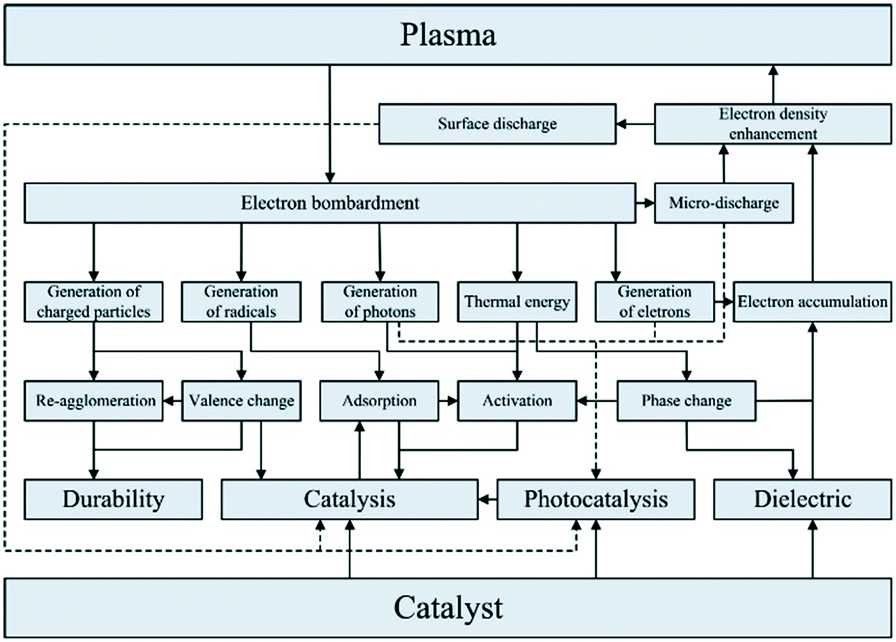
Reaction selectivity/yield control in plasma reactors is a problematic issue, mainly because of the vast numbers of vibrationally excited species and elementary reaction steps generated by the plasma. For example, full kinetic models of even such a “simple” microwave-plasma process as CO2 dissociation include 10000+ reactions and 100+ species. Such highly complex models are practically useless when it comes to the design and scale-up of a reactor and model reduction methodologies need to be developed. One of such methodologies resulted in the reduction of the CO2 dissociation model to 44 reactions and 13 species.71 In an attempt to improve product yield and selectivity, hybrid designs combining plasma with heterogeneous catalysis have been proposed. Dominant are fixed-bed systems, as the one for dry reforming of methane72 shown in Fig. 6. It must be noted, however, that the interactions between plasma and a heterogeneous catalyst are very complex (Fig. 7) and therefore present as such a significant challenge, both in terms of their detailed understanding and the mathematical modelling.
 | ||
| Fig. 6 Fixed-bed catalytic plasma reactor for dry reforming of methane. Reprinted from Chun et al.,72 with permission from MDPI. | ||
 | ||
| Fig. 7 Interactions between plasma and heterogeneous catalyst. Source: Chung and Chang;73 reprinted with permission from Elsevier. | ||
Also, the microreactor technology offers opportunities for the improved control of plasma chemistries. Here, both non-catalytic and catalytic micro- and millichannel plasma reactors have been investigated.74–78 Their expected advantages include low-power operation, improved heat transfer management, and in the case of catalytic reactors – very high surface areas offered and adequate addressing the short lifetimes of the vibrationally excited species.
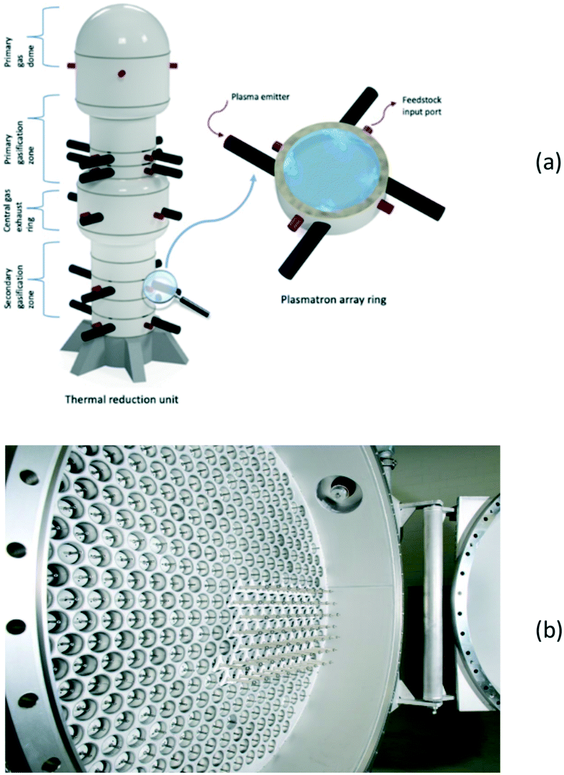
The approach to plasma reactor scale-up depends primarily on two factors: the type of plasma concerned and the intended production scale. Most large-scale thermal plasma gasification processes base on a single reactor vessel equipped with multiple plasma torches. In the case of microwave plasma, the reaction chambers can be fitted with several microwave generators and stacked on each other,79 as shown in Fig. 8a. In DBD plasma reactors, on the other hand, the numbering-up strategy prevails, that results in multitubular assemblies, as in the case of ozone generators80 (Fig. 8b).
 | ||
| Fig. 8 Scale-up of a MW-plasma reactor by stacking reactor chambers with multiple microwave generators (a), and numbering-up of DBD reactor tubes (b). Fig. 8b: © 2020 SUEZ. All rights reserved. Reprinted with permission. | ||
Despite the above-said features and despite circa four decades of research, industrial-scale applications of ultrasound in the chemical synthesis are yet to be seen. The challenges and technology development issues are as old as the technology itself and include:
• Stochastic character of the cavitation events, which makes modelling and scale-up extremely difficult.
• Lack of understanding of the relation between a cavitation collapse and chemical reactivity.
• Limited control of cavitational intensity.
• Small penetration depth of acoustic waves.
• Equipment erosion due to cavitation.
• Capacity and stability of ultrasound transducers.
• Low overall energetic efficiency (lower than in hydrodynamic cavitation reactors).
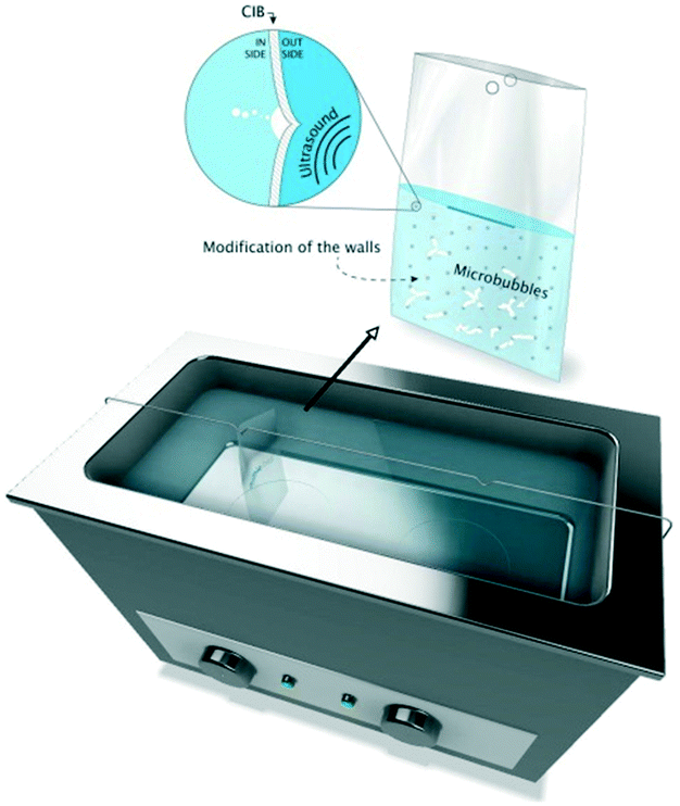
In order to address at least a part of the above challenges, various ultrasonic reactor designs have been proposed. In flow-cell reactors, the characteristics and the distribution of ultrasonic transducers, the vessel geometry, as well as the material/structure of the reactor wall play the role. Various types of magnetostrictive and piezoelectric transducers and their characteristics are discussed in the comprehensive review by Yao, et al.85 Among reactor geometries, hexagonal flow cells with triple-frequency transducers86 and rectangular flow cells with single-frequency transducers87 have been investigated on bench- and pilot-scales. Fernandez Rivas and co-authors88,89 proposed a soft-wall reactor called cavitation intensifying bag (CIB), in which the inner surface of the wall was modified with patterned pits of microscopic dimensions (Fig. 9). The patterned generation of microcavities from the pits resulted in significantly increased overall cavitation activity and energy efficiency.
 | ||
| Fig. 9 Cavitation intensifying bag reactor with patterned micropits in the walls. Source: Van Zwieten et al.89 Reprinted with permission from Elsevier. | ||
Another path to follow, in particular for small-scale applications, is to combine the ultrasound with microchannel reactor systems that offer short diffusion paths and high specific interfacial area resulting in increased mass transfer rates in multiphase reactions.90 Three different approaches are reported in the literature, of which the simplest is a microreactor capillary immersed in an ultrasonic bath91 (Fig. 10). The other two consist in having the reactor capillary in a direct or interval contact with an aluminium plate located on an ultrasonic transducer92 (Fig. 11). The interval contact can further include a temperature control medium flowing in the gap between the reaction tube and the aluminium plate.93
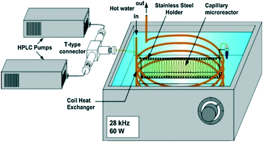 | ||
| Fig. 10 Ultrasound-assisted microreactor with the reaction tube immersed in the ultrasonic bath. Source: Aljbour, et al.91 Reprinted with permission from Elsevier. | ||
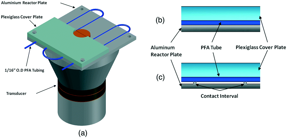 | ||
| Fig. 11 Ultrasound-assisted microreactor (a) with direct (b) or interval (c) contact between the reactor tube and the transducer. Source: John, et al.92 Reprinted with permission from Elsevier. | ||
Systems targeting thermal energy supply
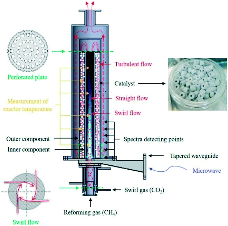
In liquids, the microwave energy transfer is realized via rotational or translational movements of, respectively, dipoles or ions in the fast-oscillating electric field component of the microwave, which causes internal friction and results in what we call the “volumetric heating”. In solid catalysts, on the other hand, the situation is more complex. Next to the dipolar dielectric loss (interaction of local dipoles, e.g., –OH, –NH3 groups, within the crystal lattice), conduction losses (interaction of ions, e.g. Na+, within the lattice) resulting from the charge carrier processes occur. Also, magnetic losses due to the interaction of the magnetic moment of the material with the magnetic field component of the microwave radiation may result in (additional) heating. Due to the above-described complexity, the response of a solid material to the microwave heating is often difficult to predict. In this regard, Nigar et al.102 developed a 3D mathematical model for a microwave heating system to predict the electric field distribution, axial and radial fixed-bed temperature profiles and temperature evolution with time for one of the widely used solid heterogeneous catalyst, i.e., NaY zeolite. The fixed-bed temperature evolution under non-steady state conditions showed the same trend as the one observed experimentally with only an average deviation of 10.3%. They highlighted that knowing the dielectric characterization of materials is crucial for predicting the heating profiles. Irrespectively of that, however, the microwave heating of solid catalysts offers interesting opportunities from the reaction engineering viewpoint: (i) one can selectively heat-up the metal nanoclusters within an otherwise microwave-neutral catalyst support,103 and (ii) one can operate at bulk gas temperature much lower than the catalyst temperature, thereby limiting the occurrence of the unwanted, homogeneous side-reactions.104
Consequently, the main challenges in applying microwave reactors on the industrial scale are different in (gas-)liquid and gas–solid systems. In liquid systems, the primary challenge consists in bringing and releasing the microwave radiation inside the reactor. Irradiating the reactor content from outside through the reactor wall, e.g. by placing the vessel in a large microwave cavity, would suffer from the limited penetration depth of the microwave and would require a reactor constructed of a microwave-transparent material, e.g., quartz, PTFE. An alternative reactor concept addressing the above challenge is presented in Fig. 12. It is the so-called internal transmission line system commercialized by company Sairem under the name LABOTRON™. In this system, the microwave is fed through a U-shaped waveguide and transmitted into the reactor via the internal transmission line that is placed in the middle of the vessel in direct contact with the reaction mixture. This allows overcoming the penetration depth limitation. The reactor itself can be made of steel, can operate under elevated pressure, and can be equipped with a cooling jacket.
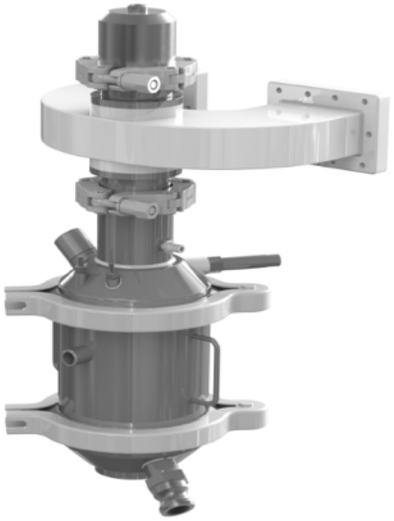 | ||
| Fig. 12 LABOTRON™ microwave reactor with internal transmission line for liquid-phase reactions. © 2020 Sairem S.A. All rights reserved. Reprinted with permission. | ||
In heterogeneously catalysed gas-phase reactions, on the other hand, the main challenge consists in achieving uniform heating of the catalyst, as conventional microwave irradiation of a bed of catalyst particles has been shown to result in very large temperature gradients, in the range of 100 K cm−1.101,105 Recently, two different reactor concepts have been developed that address the above challenge. The operational principle of the monomodal microwave reactor (MMR),106 developed at the University of Zaragoza in collaboration with the University of Valencia, is creation of a standing microwave in a specially designed cavity (Fig. 13a) and heating of a monolithic catalyst, in which the endothermic reaction takes place. In order to increase the uniformity of the heating, the same group at Zaragoza together with Danish Technological Institute implemented the rotation of the monolithic catalyst inside the cavity (Fig. 13b).
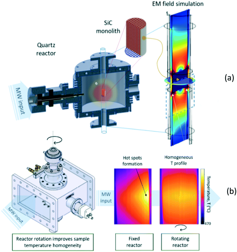 | ||
| Fig. 13 Monomodal microwave reactor; (a) – general scheme; (b) – heating uniformity improvement achieved by monolith rotation (courtesy: University of Zaragoza). | ||
A different reactor concept, the so-called traveling microwave reactor has been developed and investigated at Delft University of Technology.107 In this reactor the microwave is allowed to “travel” co-currently to the reacting gas through a bed of catalyst. The bed is positioned in the annular space between two conductors (Fig. 14a), and the non-dissipated fraction of the microwave is absorbed by a specially designed absorber at the reactor outlet. Because of the full cylindrical symmetry, the TMR ensures uniform temperature distribution in the tangential direction at each cross-section of the catalyst bed. By manipulating the catalyst distribution/voidage, a uniform longitudinal temperature profile in the bed can be obtained (Fig. 14b).
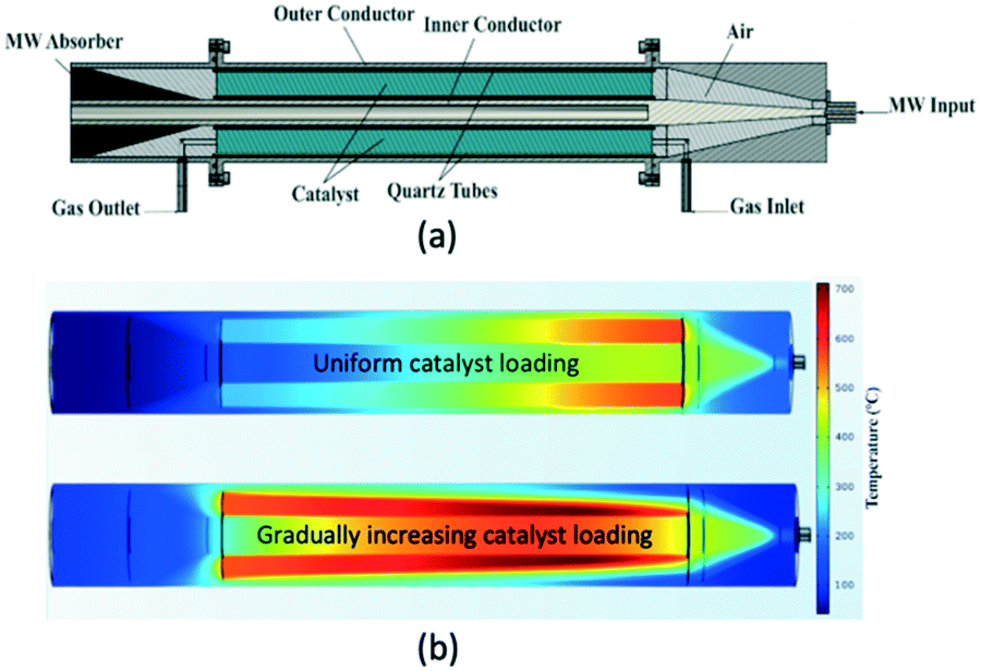 | ||
| Fig. 14 Traveling microwave reactor; (a) – scheme; (b) – heating profiles at different catalyst loading patterns: uniform and gradually increasing. | ||
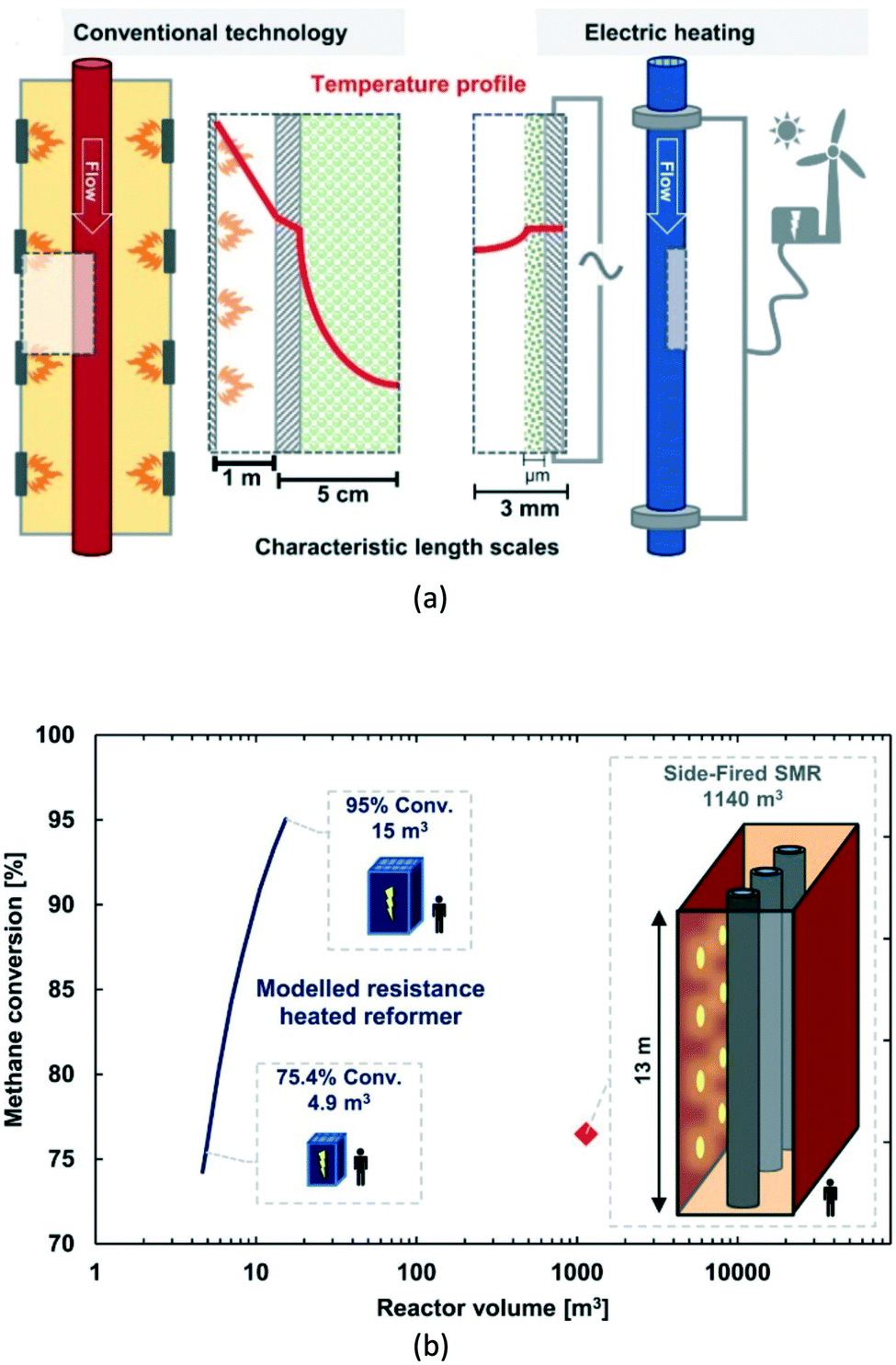 | ||
| Fig. 15 Electric resistance-heated methane steam reformer; (a) – operational principle compared to conventional technology; (b) – possible miniaturization degree of the reactor as a function of the target methane conversion. Source: Wismann, et al.111 Reprinted with permission from American Association for the Advancement of Science. | ||
Reactor concepts utilizing induction heating have quite a long history. The first publication related to this topic dates from 1952 and comes from Shell.112 The researchers investigated the possibility of using the induction heating for a very fast preheating of petroleum fractions entering a catalytic cracking unit. Such a fast preheating to very high temperatures (700 °C or more) should help to reduce thermal cracking and coke formation on the catalyst. Accordingly, an induction-heated cracking unit was designed and investigated. In the unit shown in Fig. 16, the catalyst bed is preceded by a preheater consisting of an induction coil and a bundle of gold wires. In the preheater, petroleum fractions were heated up from 400 to 700 °C in about 10 milliseconds. As a result, carbon formation in the novel reactor was less than 1/10th of that in a conventional system.
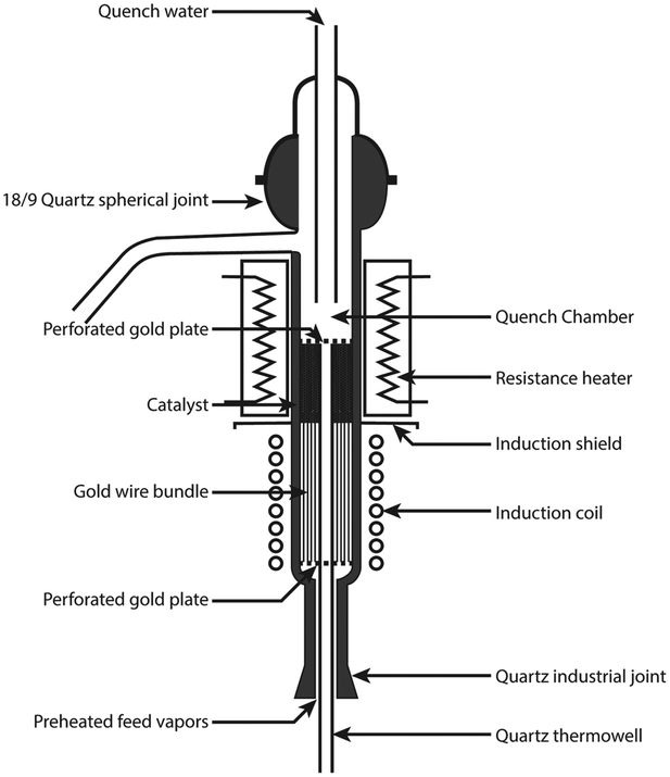 | ||
| Fig. 16 Induction-preheated reactor for catalytic cracking. Source: Archibald, et al.112 Reprinted with permission from American Chemical Society. | ||
More recently, induction-heated stirred-tank113 and fluidized-bed114 reactor concepts, both using the eddy currents mechanism, were proposed.
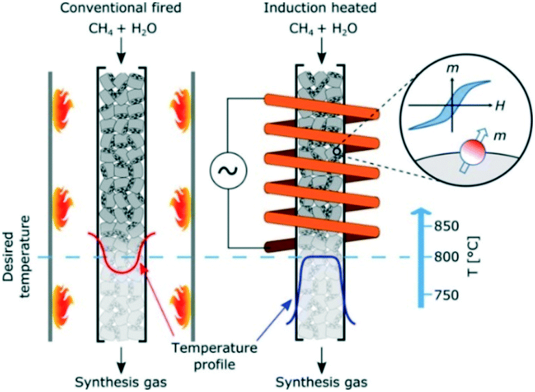
The majority of reactors utilizing the hysteresis-based induction heating are packed-bed flow systems filled with magnetic catalyst particles. The group of Kirschning115–117 investigated inductive heating in relation to organic synthesis in microreactors. The heating in the reactor channels was realized via superparamagnetic core–shell nanoparticles, e.g., silica-coated manganese ferrite particles. This led to significantly shorter reaction times and higher yields than in the corresponding batch reactors. Also, an important advantage mentioned by the authors was the simplicity of the induction-heated microreactor in comparison with its microwave-heated counterpart. Rebrov and co-workers118 designed and investigated a hysteresis-heated micro-trickle-bed reactor for two-step conversion of citronella to menthol, while the group of Chaudret carried out continuous CO2 hydrogenation in magnetically-induced flow reactor filled with composite iron carbide nanoparticles.119 Finally, Mortensen and co-workers120 demonstrated a catalytic flow reactor system for methane steam reforming, using induction-heated supported magnetic nickel–cobalt nanoparticles (Fig. 17). The Co-component of the catalyst with high Curie temperature provided enough heat to carry out high-temperature endothermic reaction catalysed by the Ni-component.
Conclusions
At dawn of the renewable electricity age, chemical reactor engineering has developed plurality of electricity-driven reactor concepts utilizing various energy transfer mechanisms. Those concepts cover not only the electrochemical conversion of water, CO2, and nitrogen to hydrogen, syngas or ammonia, but are applicable to a broad range of chemical and catalytic reactions at various production scales – see Table 3.| Reactor type | Commercially applied?/feasible production scales | Scale-up difficulty | Phases present (G-gas; L-liquid; S-solid) | |||
|---|---|---|---|---|---|---|
| G | (G)/L | G/S | (G)/L/S | |||
| Electrochemical | YES/small to very large | Intermediate | O | O | ||
| Photochemical | YES/small to large | Intermediate | O | O | O | |
| Plasma | YES/small to large | Difficult | O | O | ||
| Sonochemical | NO/small to medium | Difficult | O | O | ||
| Microwave-heated | YES/small to medium | Difficult | O | O | O | |
| Resistance-heated | NO/small to large | Intermediate | O | O | ||
| Induction-heated | NO/small to large | Intermediate | O | O | O | O |
The technology maturity (or technology readiness level, TRL) of the electricity-driven reactors varies widely from the proof-of-concept stage (e.g. sonochemical reactors) up to commercially operating large-scale units (e.g. photoreactors). The most important challenges in further development include spatial and temporal control of the electricity-generated fields, design and fabrication of energy-responsive catalysts, and overall energetic efficiency. To address those challenges, a more intensive multidisciplinary research involving catalysis, physics, materials science, electrical and chemical engineering is necessary. Better fundamental understanding of the underlying phenomena and interrelations will result in the development of novel energy-responsive catalysts and reactor systems with enhanced field control. Also, standard chemical reaction engineering courses in university curricula will need to be modernized, to include more elements of electricity-based reactor modelling and design.
With renewable electricity becoming the most widely available, versatile energy form on Earth, the electricity-driven reactors discussed in the present paper will play a crucial role in the transition to green, environmentally-neutral manufacturing of fuels and chemicals. Circa 3.5 billion years ago, electricity might have triggered the appearance of life on Earth.121,122 Electricity in chemical reactors may nowadays help preserve life on Earth for ages to come.
Conflicts of interest
There are no conflicts to declare.References
-
U.S. Energy Information Administration, Annual Energy Outlook 2019I, January 2019 (https://www.eia.gov/energyexplained/use-of-energy/industry.php)
.
- S. Lechtenböhmer, L. J. Nilsson, M. Åhman and C. Schneider, Energy, 2016, 115, 1623–1631 CrossRef
- D. Parra, X. Zhang, C. Bauer and M. K. Patel, Appl. Energy, 2017, 193, 440–454 CrossRef
- S. R. Foit, I. C. Vinke, L. G. J. de Haart and R.-A. Eichel, Angew. Chem., Int. Ed., 2017, 56, 5402–5411 CrossRef CAS PubMed
- C. Wulf, J. Linssen and P. Zapp, Energy Procedia, 2018, 115, 367–378 CrossRef
- H. Blanco, W. Nijs, J. Ruf and A. Faaij, Appl. Energy, 2018, 232, 617–639 CrossRef
- J. Guilera, J. R. Morante and T. Andreu, Energy Convers. Manage., 2018, 162, 218–224 CrossRef CAS
- F. M. Sapountzi, J. M. Garcia, C. J. Weststrate, H. O. A. Friedriksson and J. W. Niemantsverdriet, Prog. Energy Combust. Sci., 2017, 58, 1–35 CrossRef
- M. Schalenbach, A. R. Zeradjanin, O. Kasian, S. Cherevko and K. J. J. Mayrhofer, Int. J. Electrochem. Sci., 2018, 13, 1173–1226 CrossRef CAS
- N. Mahmood, Y. Yao, J.-W. Zhang, L. Pan, X. Zhang and J.-J. Zou, Adv. Sci., 2018, 5, 1700464 CrossRef PubMed
- H. R. Jhong, S. Ma and P. J. A. Kenis, Curr. Opin. Chem. Eng., 2013, 2, 191–199 CrossRef
- C.-T. Dinh, T. Burdyny, M. G. Kibria, A. Seifitokaldani, C. M. Gabardo, F. P. Garcia de Arquer, A. Kiani, J. P. Edwards, P. De Luna, O. S. Bushuyev, C. Zou, R. Quintero-Bermudez, Y. Pang, D. Sinton and E. H. Sargent, Science, 2018, 360, 783–787 CrossRef CAS PubMed
- M. Jouny, W. Luc and F. Jiao, Ind. Eng. Chem. Res., 2018, 57, 2165–2177 CrossRef CAS
- O. Gutiérez Sánchez, Y. Y. Birdja, M. Bulut, J. Vaes, T. Breugelmans and D. Pant, Curr. Opin. Green Sustain. Chem., 2019, 16, 47–56 CrossRef
- F. Zhang, H. Zhang and Z. Liu, Curr. Opin. Green Sustain. Chem., 2019, 16, 77–84 CrossRef
- T. Burdyny and W. A. Smith, Energy Environ. Sci., 2019, 12, 1442–1453 RSC
- W. A. Smith, T. Burdyny, D. A. Vermaas and H. Geerlings, Joule, 2019, 3, 1822–1834 CrossRef CAS
- V. Kyriakou, I. Garagounis, E. Vasileiou, A. Vourros and M. Stoukides, Catal. Today, 2017, 286, 2–13 CrossRef CAS
- L. Wang, M. Xia, H. Wang, K. Huang, C. Quian, C. T. Maravelias and G. A. Ozin, Joule, 2018, 2, 1055–1074 CrossRef CAS
- R. Zhao, H. Xie, L. Chang, X. Zhang, X. Zhu, X. Tong, T. Wang, Y. Luo, P. Wei, Z. Wang and X. Sun, EnergyChem, 2019, 1, 100011 CrossRef
- C. A. Sequeira and D. M. F. Santos, J. Braz. Chem. Soc., 2009, 20, 387–406 CrossRef CAS
- K. Scott, Dev. Chem. Eng. Miner. Process., 1993, 1, 71–117 CrossRef CAS
- R. J. Marshall and F. C. Walsh, Surf. Technol., 1985, 24, 45–77 CrossRef CAS
-
F. C. Walsh and D. Pletcher, in Developments in Electrochemistry: Science Inspired by Martin Fleischmann, ed. D. Pletcher, Z.-Q. Tian and D. E. Williams, J. Wiley & Sons, 2014, pp. 95–11 Search PubMed
- F. Walsh and G. Reade, Analyst, 1994, 119, 791–796 RSC
-
A. H. Sulaymon and A. H. Abbar, in Electrolysis, ed. J. Kleperis and V. Linkov, In-Tech Opne, 2012, pp. 189–202 Search PubMed
- D. Pletcher, J. Appl. Electrochem., 1984, 14, 403–415 CrossRef CAS
- J. O. M. Bockris, J. Serb. Chem. Soc., 2005, 70, 475–487 CrossRef CAS
- N. Munichandraiah, J. Indian Inst. Sci., 2010, 90, 261–270 CAS
-
C. M. A. Brett and A. M. C. F. Oliveira Brett, in Surface Engineering, ed. R. Kossowsky and S. C. Singhal, Springer, Dordrecht, 1984, pp. 656–664 Search PubMed
- N. Menzel, E. Ortel, R. Kraehnert and P. Strasser, ChemPhysChem, 2012, 13, 1385–1394 CrossRef CAS PubMed
- W. Zhu, R. Zhang, F. Qu, A. M. Asiri and X. Sun, ChemCatChem, 2017, 9, 1721–1743 CrossRef CAS
- S. Vasudevan, Res. J. Chem. Sci., 2013, 3, 1–3 Search PubMed
- H. Jaroszek and P. Dydo, Open Chem., 2015, 14, 1–19 Search PubMed
- M. Paidar, V. Fateev and K. Bouzek, Electrochim. Acta, 2016, 209, 737–756 CrossRef CAS
- D. E. Blanco and M. A. Modestino, Trends in Chemistry, 2019, 1, 9–10 CrossRef
-
N. Aust, in Encyclopedia of Applied Electrochemistry, ed. G. Kreysa, K. Ota and R. F. Savinell, Springer, New York, 2014, pp. 1392–1397 Search PubMed
-
M. Fleischmann, R. E. W. Jansson, G. A. Ashworth and P. J. Eyre, British Pat., 1504690, 1974 Search PubMed
- P. Granados Mendoza, S. Moshtarikhah, A. S. Langenhan, M. T. de Groot, J. T. F. Keurentjes, J. C. Schouten and J. van der Schaaf, Chem. Eng. Res. Des., 2017, 128, 120–129 CrossRef CAS
- F. J. Del Campo, Electrochem. Commun., 2014, 45, 91–94 CrossRef CAS
- M. A. Modestino, D. Fernandez Rivas, M. S. H. Hashemi, J. G. E. Gardeniers and D. Psaltis, Energy Environ. Sci., 2016, 9, 3381–3391 RSC
- G. Laudadio, W. De Smet, L. Struik, Y. Cao and T. Noël, J. Flow Chem., 2018, 8, 157–165 CrossRef PubMed
- W. Hirschkind, Ind. Eng. Chem., 1949, 41, 2749–2752 CrossRef CAS
- Y. Ito and S. Matsuda, Ann. N. Y. Acad. Sci., 1969, 147, 618–624 CrossRef CAS
- M. Sender and D. Ziegenbalg, Chem. Ing. Tech., 2017, 89, 1159–1173 CrossRef CAS
- Y. Su, N. J. W. Straathof, V. Hessel and T. Noël, Chem. – Eur. J., 2014, 20, 10562–10589 CrossRef CAS PubMed
- S. Elgue, T. Aillet, K. Loubiere, A. Conté, O. Dechy-Cabaret, L. Prat, C. R. Horn, O. Lobet and S. Vallon, Chim. Oggi, 2015, 33(5), 58–61 Search PubMed
- D. Cambié, C. Bottecchia, N. J. W. Straathof, V. Hessel and T. Noël, Chem. Rev., 2016, 116, 10276–10341 CrossRef PubMed
- K. Loubiere, M. Oelgemoeller and T. Aillet, Chem. Eng. Process., 2016, 104, 120–132 CrossRef CAS
- K. C. Harper, E. G. Moschetta, S. V. Bordawekar and S. J. Wittenberger, ACS Cent. Sci., 2019, 5, 109–115 CrossRef CAS PubMed
- T. Van Gerven, G. Mul, J. Moulijn and A. Stankiewicz, Chem. Eng. Process., 2007, 46, 781–789 CrossRef CAS
-
F. Khodadadian, M. Nasalevich, F. Kapteijn, A. I. Stankiewicz, R. Lakerveld and J. Gascon, in Alternative Energy Sources for Green Chemistry, ed. G. D. Stefanidis and A. I. Stankiewicz, The Royal Society of Chemistry, 2016, pp. 227–269 Search PubMed
- J. L. Gole, A. Fedorov, P. Hesketh and C. Burda, Phys. Status Solidi C, 2004, 1, S188–S197 CrossRef
- P. Ciambelli, D. Sannino, V. Palma, V. Vaiano and R. S. Mazzei, Photochem. Photobiol. Sci., 2011, 10, 414–418 RSC
- P. Wang, B. Huang, Y. Daia and M.-H. Whangbo, Phys. Chem. Chem. Phys., 2012, 14, 9813–9825 RSC
- X. Zhang, Y. L. Chen, R.-S. Liu and D. P. Tsai, Rep. Prog. Phys., 2013, 76, 046401 CrossRef PubMed
- K. H. Leong, A. A. Aziz, L. C. Sim, P. Saravanan, M. Jang and D. Bahnemann, Beilstein J. Nanotechnol., 2018, 9, 628–648 CrossRef CAS PubMed
- M. Grätzel, Nature, 2001, 414, 338–344 CrossRef PubMed
- P. Lianos, Appl. Catal., B, 2017, 210, 235–254 CrossRef CAS
-
P. Dias and A. Mendes, in Encyclopedia of Sustainability, Science and Technology, ed. R. A. Meyers, Springer, 2018, pp. 1–52, DOI:10.1007/978-1-4939-2493-6_957-1
- M. Ahmed and I. Dincer, Int. J. Hydrogen Energy, 2019, 44, 2474–2507 CrossRef CAS
- V. J. Ibberson and M. W. Thring, Ind. Eng. Chem., 1969, 61(11), 48–61 CrossRef CAS
-
P. Pässler, W. Hefner, K. Buckl, H. Meinass, A. Meiswinkel, H.-J. Wernicke, G. Ebersberg, R. Müller, J. Bässler, H. Behringer and D. Mayer, in Ulmann's Encyclopedia of Industrial Chemistry, Wiley-VCH, 2008, vol. 1, pp. 277–326 Search PubMed
- U. Kogelschatz, Plasma Chem. Plasma Process., 2003, 23, 1–46 CrossRef CAS
- T. Kuroki, H. Fujishima, K. Otsuka, T. Ito, M. Okubo, T. Yamamoto and K. Yoshida, Thin Solid Films, 2008, 516, 6704–6709 CrossRef CAS
- H.-H. Kim, Plasma Processes Polym., 2004, 1, 91–110 CrossRef CAS
-
A. Fridman, Plasma Chemistry, Cambridge, 1st edn, 2008 Search PubMed
- A. Bogaerts, T. Kozák, K. Van Laer and R. Snoeckx, Faraday Discuss., 2015, 183, 217–232 RSC
- E. Delikonstantis, M. Scapinello and G. D. Stefanidis, Processes, 2019, 7, 68 CrossRef CAS
- M. Scapinello, E. Delikonstantis and G. D. Stefanidis, Fuel, 2018, 222, 705–710 CrossRef CAS
- J. F. De la Fuente, S. H. Moreno, A. I. Stankiewicz and G. D. Stefanidis, React. Chem. Eng., 2016, 1, 540–554 RSC
- S. M. Chun, D. H. Shin, S. H. Ma, G. W. Yang and Y. C. Hong, Catalysts, 2019, 9, 292 CrossRef
- W.-C. Chung and M.-B. Chang, Renewable Sustainable Energy Rev., 2016, 62, 13–31 CrossRef CAS
- C. Trionfetti, A. Ağıral, J. G. E. Gardeniers, L. Lefferts and K. Seshan, J. Phys. Chem. C, 2008, 112, 4267–4274 CrossRef CAS
- A. Ağıral, L. Lefferts and J. G. E. Gardeniers, IEEE Trans. Plasma Sci., 2009, 37, 985–992 Search PubMed
- A. Ağıral, T. Nozaki, M. Nakase, S. Yuzawa, K. Okazaki and J. G. E. Gardeniers, Chem. Eng. J., 2011, 167, 560–566 CrossRef
- G. Schelcher, C. Guyon, S. Ognier, S. Cavadias, E. Martinez, V. Taniga, L. Malaquin, P. Tabeling and M. Tatoulian, Lab Chip, 2014, 14, 3037–3042 RSC
- J. Wengler, S. Ognier, M. Zhang, E. Levernier, C. Guyon, C. Ollivier, L. Fensterbank and M. Tatoulian, React. Chem. Eng., 2018, 3, 930–941 RSC
- J. F. De la Fuente, A. A. Kiss, M. T. Radoiu and G. D. Stefanidis, J. Chem. Technol. Biotechnol., 2017, 92, 2495–2505 CrossRef CAS
- C. Wei, F. Zhang, Y. Hu, C. Feng and H. Wu, Rev. Chem. Eng., 2017, 33, 49–89 CAS
- L. H. Thompson and L. K. Doraiswamy, Ind. Eng. Chem. Res., 1999, 38, 1215–1249 CrossRef CAS
- A. Kumar, P. R. Gogate, A. B. Pandit, H. Delmas and A. M. Wilhelm, Ind. Eng. Chem. Res., 2004, 43, 1812–1819 CrossRef CAS
-
U. Neis, TU Hamburg-Harburg Reports on Sanitary Engineering, 2002, vol. 35, pp. 79–90 Search PubMed
- F. Laugier, C. Andriantsiferana, A. M. Wilhelm and H. Delmas, Ultrason. Sonochem., 2008, 15, 965–972 CrossRef CAS PubMed
- Y. Yao, Y. Pan and S. Liu, Ultrason. Sonochem., 2019 DOI:10.1016/j.ultsonch.2019.104722
- P. R. Gogate, S. Mujumdar and A. B. Pandit, Adv. Environ. Res., 2003, 7, 283–299 CrossRef CAS
- A. S. Mhetre and P. R. Gogate, Chem. Eng. J., 2014, 258, 69–76 CrossRef CAS
- D. Fernandez Rivas, B. Verhaagen, A. Galdamez Perez, E. Castro-Hernandez, R. van Zwieten and K. Schroën, J. Phys.: Conf. Ser., 2015, 656, 012112 CrossRef
- R. van Zwieten, B. Verhaagen, K. Schroën and D. Fernández Rivas, Ultrason. Sonochem., 2017, 36, 446–453 CrossRef CAS PubMed
- S. Hübner, S. Kressirer, D. Kralisch, C. Bludszuweit-Philipp, K. Lukow, I. Jänich, A. Schilling, H. Hieronymus, C. Liebner and K. Jähnisch, ChemSusChem, 2012, 5, 279–288 CrossRef PubMed
- S. Aljbour, T. Tagawa and H. Yamada, J. Ind. Eng. Chem., 2009, 15, 829–834 CrossRef CAS
- J. J. John, S. Kuhn, L. Braeken and T. Van Gerven, Chem. Eng. Process., 2017, 113, 35–41 CrossRef CAS
- J. J. John, S. Kuhn, L. Braeken and T. Van Gerven, Chem. Eng. Res. Des., 2017, 125, 146–155 CrossRef CAS
- R. Gedye, F. Smith, K. Westaway, H. Ali, L. Baldisera, L. Laberge and J. Rousell, Tetrahedron Lett., 1986, 27, 279–282 CrossRef CAS
- C. O. Kappe, Angew. Chem., Int. Ed., 2004, 43, 6250–6284 CrossRef CAS PubMed
- M. Nüchter, B. Ondruschka, W. Bonrath and A. Gum, Green Chem., 2004, 6(3), 128–141 RSC
- C. O. Kappe and E. Van der Eycken, Chem. Soc. Rev., 2010, 39, 1280–1290 RSC
- D. Bogdal and A. Prociak, Gendai Kagaku, 2007, 25, 42–44 Search PubMed
- R. Hoogenboom and U. Schubert, Macromol. Rapid Commun., 2007, 28, 368–386 CrossRef CAS
- C. Ebner, T. Bodner, F. Stelzer and F. Wiesbrock, Macromol. Rapid Commun., 2011, 32, 254–288 CrossRef CAS PubMed
- T. Durka, T. Van Gerven and A. Stankiewicz, Chem. Eng. Technol., 2009, 32, 1301–1312 CrossRef CAS
- H. Nigar, G. S. J. Sturm, B. Garcia-Baños, F. L. Peñaranda-Foix, J. M. Catalá-Civera, R. Mallada, A. Stankiewicz and J. Santamaría, Appl. Therm. Eng., 2019, 155, 226–238 CrossRef CAS
- X. Zhang, D. O. Hayward and D. M. P. Mingos, Ind. Eng. Chem. Res., 2001, 40, 2810–2817 CrossRef CAS
- A. Ramirez, J. L. Hueso, M. Abian, M. U. Alzueta, R. Mallada and J. Santamaria, Sci. Adv., 2019, 5, eaau9000 CrossRef CAS PubMed
- I. de Dios García, A. Stankiewicz and H. Nigar, Catal. Today, 2020 Search PubMed
- I. Julian, H. Ramirez, J. L. Hueso, R. Mallada and J. Santamaria, Chem. Eng. J., 2019, 377, 119764 CrossRef
- F. Eghbal Sarabi, M. Ghorbani, A. Stankiewicz and H. Nigar, Chem. Eng. Res. Des., 2020, 153, 677–683 CrossRef CAS
- S. Roux, M. Courel, L. Picart-Palmade and J.-P. Pain, J. Food Eng., 2010, 98, 398–407 CrossRef CAS
- J. Pinto, V. L. M. Silva, A. M. G. Silva, A. M. S. Silva, J. C. S. Costa, L. M. N. B. F. Santos, R. Enes, J. A. S. Cavaleiro, A. A. M. O. S. Vicente and J. A. C. Teixeira, Green Chem., 2013, 15, 970–975 RSC
- J. Li, X. Lu, F. Wu, W. Cheng, W. Zhang, S. Qin, Z. Wang and Z. You, Ind. Eng. Chem. Res., 2017, 56, 12520–12528 CrossRef CAS
- S. T. Wismann, J. S. Engbæk, S. B. Vendelbo, F. B. Bendixen, W. L. Eriksen, K. Aasberg-Petersen, C. Frandsen, I. Chorkendorff and P. M. Mortensen, Science, 2019, 364, 756–759 CrossRef CAS PubMed
- R. C. Archibald, N. C. May and B. S. Greensfelder, Ind. Eng. Chem., 1952, 44, 1811–1817 CrossRef CAS
- V. Fireteanu, B. Paya, J. Nuns, Y. Neau, T. Tudorache and A. Spahiu, COMPEL - The international journal for computation and mathematics in electrical and electronic engineering, 2005, 24, 324–333 CrossRef
- M. Latifi and J. Chaouki, AIChE J., 2015, 61, 1507–1523 CrossRef CAS
- S. Ceylan, C. Friese, C. Lammel, K. Mazac and A. Kirschning, Angew. Chem., Int. Ed., 2008, 47, 8950–8953 CrossRef CAS PubMed
- S. Ceylan, L. Coutable, J. Wegner and A. Kirschning, Chem. – Eur. J., 2011, 17, 1884–1893 CrossRef CAS PubMed
- A. Kirschning, L. Kupracz and J. Hartwig, Chem. Lett., 2012, 41, 562–570 CrossRef CAS
- S. Chatterjee, V. Degirmenci and E. V. Rebrov, Chem. Eng. J., 2015, 281, 884–891 CrossRef CAS
- A. Bordet, L.-M. Lacroix, P.-F. Fazzini, J. Carrey, K. Soulantica and B. Chaudret, Angew. Chem., Int. Ed., 2016, 55, 15894–15898 CrossRef CAS PubMed
- P. M. Mortensen, J. S. Engbæk, S. B. Vendelbo, M. F. Hansen and M. Østberg, Ind. Eng. Chem. Res., 2017, 56, 14006–14013 CrossRef CAS
- S. L. Miller, Science, 1953, 117, 528–529 CrossRef CAS PubMed
- S. L. Miller and H. C. Urey, Science, 1959, 130, 245–251 CrossRef CAS
| This journal is © The Royal Society of Chemistry 2020 |