DOI:
10.1039/D0RA07227C
(Paper)
RSC Adv., 2020,
10, 35062-35071
Thermodynamic analysis of dissociation of periodic dislocation dipoles in isotropic crystals
Received
22nd August 2020
, Accepted 2nd September 2020
First published on 22nd September 2020
Abstract
In the past, experimentally observed dislocations were often interpreted using an isolated dislocation assumption because the effect of background dislocation density was difficult to evaluate. Contrarily, dislocations caused by atomistic simulations under periodic boundary conditions can be better interpreted because linear elastic theory has been developed to address the effect of periodic dislocation array in the literature. However, this elastic theory has been developed only for perfect dislocations, but not for dissociated dislocations. The periodic boundary conditions may significantly change the dissociation energy of dislocations and stacking fault width, which in turn, change the deformation phenomena observed in simulations. To enable materials scientists to understand the dislocation behavior under the periodic boundary conditions, we use isotropic elastic theory to analyze the thermodynamics of dissociated periodic dislocations with an arbitrary dislocation character angle. Analytical expressions for force, stacking fault width, and energies are presented in the study. Results obtained from the periodic dislocation array were compared with those obtained from isolated dislocations to shed light on the interpretation of experimentally observed and simulated dislocations.
1. Introduction
Dislocations observed in microscopic experiments are often interpreted using linear elastic theory without considering dislocation–dislocation interactions. Analogously, atomistic simulations often require periodic boundary conditions where any individual dislocation could be imaged into an infinite dislocation array. The linear elastic theory of dislocation array can be used to address the effect of periodic boundary conditions. One successful example is the calculation of dislocation core energies by fitting the linear elastic expression into atomistic simulation data based on an isotropic assumption.1–6 These studies suggested that the effect of periodic boundary conditions is significant and cannot be ignored. Unfortunately, this former linear elastic theory has been developed only for perfect dislocations. A similar theory for dissociated dislocations is not available, but is critical for researchers to explain the dissociation energy, stacking fault width, and the consequent deformation phenomena observed in simulations.
Concerning an infinite dislocation array, the total elastic energy involved is an infinite sum. Some previous studies performed this summation numerically, where a conditional divergence problem was reported and was dealt with using sophisticated algorithms.2–4 Under the isotropic condition, we derived a semi-analytical expression for the total elastic energy of the undissociated dislocation dipole array with fast convergence.5,6 The purpose of this study is to extend our previous work5,6 to include dissociated dislocations in isotropic materials. Semi-analytical expressions will be given for force, stacking fault width, and energy for dissociated dislocations and results will be discussed with reference to isolated dislocations.
2. Forces between partials
(A) Analytical expression for force
The simplest dislocations that can be simulated under the periodic boundary conditions are dislocation dipoles. Geometries of our three-dimensional periodic dislocation dipoles are illustrated in Fig. 1, where the orange frames highlight the unit cell at the origin i, j = 0, 0 whose dimensions in x and y directions are respectively Lx and Ly. Under the periodic boundary conditions, such a unit cell can be viewed as being infinitely repeated in space i, j = −∞, …, +∞. Each cell contains one dislocation dipole whose separation distance is d. In Fig. 1(a), dislocations are undissociated and the two dislocations of the dipole in each cell are marked as αi,j and α′i,j respectively. In Fig. 1(b), the dislocation αi,j is dissociated into two partials ai,j and bi,j, and the dislocation α′i,j is dissociated into two partials a′i,j and b′i,j. To clearly distinguish the two arrays of partials, one is coloured black and the other one is coloured blue.
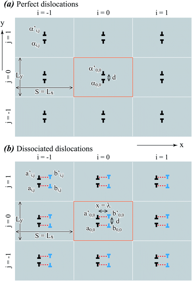 |
| | Fig. 1 Geometries for periodic dislocation dipole arrays: (a) perfect dislocations and (b) dissociated dislocations. | |
The stacking fault width λ shown in Fig. 1(b) is a technologically important property. To understand λ, the x component of the force between the black and blue partial dislocations needs to be understood. In a per dislocation unit, this force can be calculated as the total x-component force between a chosen blue dislocation (say, b0,0) and all the black dislocations in the array. If the character angle and Burgers magnitude of the undissociated dislocation are β and b, the character angles of the two partials are β + π/6 and β − π/6 respectively, and both partials have the same Burgers magnitude of  . When a blue dislocation is separated from the black dislocation by x and y in the horizontal and vertical directions, the black dislocation will apply an x-component force to the blue dislocation:7
| |
 | (1) |
where
G is the shear modulus and
ν is Poisson's ratio. Now, we consider the interaction between the blue dislocation and any vertical column of black dislocations shown in
Fig. 1(b). As will be clear below, the column-by-column derivation of the interaction can eliminate the conditional divergence problem. Assume that the blue dislocation is horizontally separated from the black dislocation column by
x1, the dislocation column will apply a total
x-component force
fx,col(
x1) to the blue dislocation.
fx,col(
x1) can be written as
| |
 | (2) |
where functions
c1e(
x1) and
c1s(
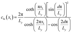
x1) are expressed as
| |
 | (3) |
| |
 | (4) |
Eqn (3) and (4) essentially sum up the interaction between the blue dislocation and the dislocations in the column in the sequence of their separation distances in y: 0, d, Ly, Ly, Ly − d, Ly + d, 2Ly, 2Ly, 2Ly − d, 2Ly + d, …, this sequence is followed to ensure convergence. For instance, it will have a conditional divergence problem if  is written as
  . The infinite summations in eqn (3) and (4) have closed-form solutions written as follows:
| |
 | (5) |
| |
 | (6) |
where csch(), coth(), and cosh() are the hyperbolic cosecant, cotangent, and cosine functions respectively. Obtaining the closed-form solution for
eqn (3) and
(4) eliminates the conditional divergence problem. The force
fx,array(
x) applied by the entire black dislocation array to the blue dislocation can be expressed as a function of partial separation distance
x.
fx,array(
x) can be obtained similarly as follows:
| |
 | (7) |
where functions
c2e and
c2s are expressed as follows:
| |
 | (8) |
| |
 | (9) |
Eqn (8) and (9) essentially sum up the interaction between the blue dislocation and the black dislocation columns in the sequence of column location x1 = x, Lx + x, Lx − x, 2Lx + x, 2Lx − x, …. We cannot find closed-form solutions for eqn (8) and (9). This is not important because eqn (8) and (9) converge rapidly. We can illustrate this by examining the convergence curves of c2e and c2s as a function of number of summation terms N. We note that eqn (8) and (9) involve four parameters Lx, Ly, d, and x, so Fig. 2(a)–(d) show the convergence curves at four representative sets of parameters (Lx, Ly, d, and x). Here, we fix Ly = 2d because this gives a maximum dislocation dipole energy,5,6 and fix Ly = 420 Å because from eqn (5)–(9), the convergence depends primarily on Lx/Ly (note x1 = j × Lx + x, j = 1, 2, …), so that we only need to explore the Lx effect at a given Ly. Physically, a large Lx means that the next column is farther away, and a small Ly means that opposite elastic fields of dislocation dipoles along the y direction cancel more quickly.
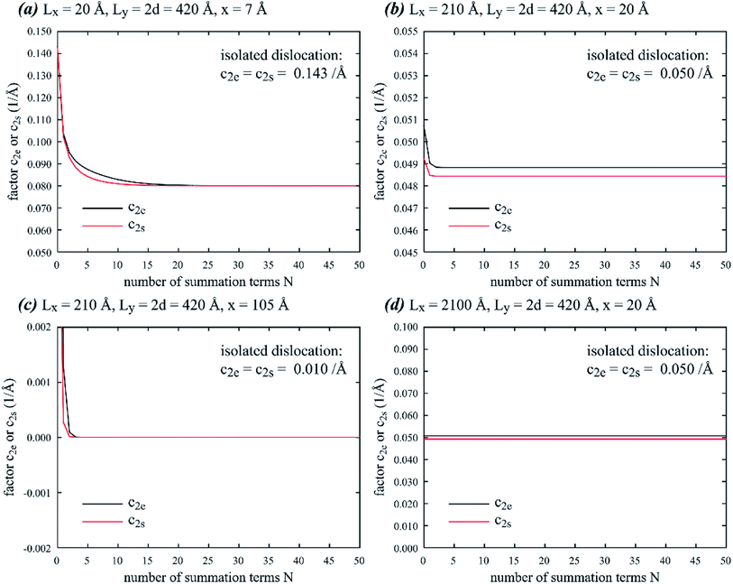 |
| | Fig. 2 Factors c2e and c2s as a function of summation number N at four different sets of geometric parameters: (a) Lx = 20 Å, Ly = 2d = 420 Å, x = 7 Å, (b) Lx = 210 Å, Ly = 2d = 420 Å, x = 20 Å, (c) Lx = 210 Å, Ly = 2d = 420 Å, x = 105 Å, and (d) Lx = 2100 Å, Ly = 2d = 420 Å, x = 20 Å. | |
Fig. 2 confirms that eqn (8) and (9) converge extremely fast especially for large Lx values. For instance, at Lx = 2100 Å (Fig. 2(d)), convergence is achieved without any summation terms. Convergence is relatively slower at smaller Lx, but even at Lx = 20 Å which is below the dimension used in most atomistic simulations, the convergence is still well achieved with about 25 summation terms. Interestingly, unlike the isolated dislocation where c2e(x) = c2s(x) = 1/x, c2e(x) and c2s(x) under the periodic boundary conditions are in some cases not equal. They can also differ significantly from the isolated dislocation case, meaning that the effect of the periodic boundary conditions on dislocation dissociation cannot be ignored. For the cases we tested, only when periodic length Lx and Ly are both large and the partial separation distance x is small (Fig. 2(d)), will c2e(x) and c2s(x) both approach the value for isolated dislocation.
In the following calculations, we will use summation number N = 100, which will ensure convergence according to Fig. 2.
(B) Comparison of force with isolated dislocation
Eqn (7) indicates that the force between partials is determined by functions c2e(x) and c2s(x). Hence, comparison of force between periodic partials and isolated pairs of partials can be achieved by comparing c2e(x) and c2s(x), which, for isolated partials, satisfy c2e(x) = c2s(x) = 1/x. Fig. 3 compares results from periodic and isolated partials on factors c2e(x) and c2s(x) as a function of partial separation distance x at different dipole lengths d, and x and y dimensions Lx and Ly: (a) d = 15 and 150 Å, Lx = 200 Å, Ly = 300 Å; (b) d = 1 and 10 Å, Lx = 200 Å, Ly = 20 Å; (c) d = 15 and 150 Å, Lx = 20 Å, Ly = 300 Å; and (d) d = 1 and 10 Å, Lx = 20 Å, Ly = 20 Å. Fig. 3 indicates that when the plot range x spans the entire periodic length Lx, c2e(x) and c2s(x) are antisymmetric at x = Lx/2 where force would drop to zero (c2e = c2s = 0). This is a validation of the results because from Fig. 1(b), any partial dislocation, say, b0,0, would be subject to equal forces from neighbouring partials, say a0,0 and a1,0, in opposite directions when x = Lx/2. As a result, zero force would be achieved at the antisymmetric middle point x = Lx/2. Because c2e(x) and c2s(x) always drop to zero at x = Lx/2 while the function 1/x does not have this feature, Fig. 3 confirms that the force between periodic partials is significantly different from that between isolated partials when x approaches Lx/2. However, when x ≪ Lx/2, the force between periodic partials can be quite close to that between isolated partials if the dipole length d is large enough. The exception is when d is small, where c2e(x) and c2s(x) are significantly lower than 1/x. This is because the dislocation dipole increasingly annihilates when d reduces. Like Fig. 2, Fig. 3 also shows that c2e(x) and c2s(x) can be different in some cases.
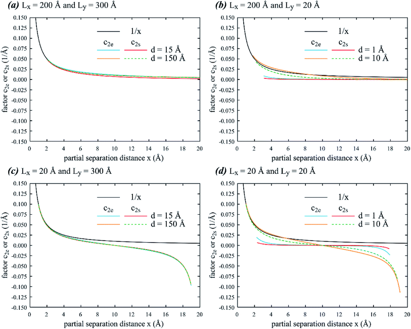 |
| | Fig. 3 Factors c2e and c2s as a function of partial separation distance x at different dipole lengths d, and x and y dimensions Lx and Ly: (a) d = 15 and 150 Å, Lx = 200 Å, Ly = 300 Å; (b) d = 1 and 10 Å, Lx = 200 Å, Ly = 20 Å; (c) d = 15 and 150 Å, Lx = 20 Å, Ly = 300 Å; and (d) d = 1 and 10 Å, Lx = 20 Å, Ly = 20 Å. | |
(C) Stacking fault width
Stacking fault width λ results from the balance between dislocation force fx,array and stacking fault energy force γ, and it can therefore be solved from
For isolated dislocation, stacking fault width is
| |
 | (11) |
We now compare stacking fault width of periodic and isolated partials using parameters derived from an aluminum interatomic potential:5,8 G = 0.1830 eV Å−3, ν = 0.3874, b = 2.864 Å, and γ = 0.0083 eV Å−2. Fig. 4(a) and (b) show, respectively, stacking fault width λ of edge and screw dislocations as a function of Lx at different combinations of Ly and d, where the λ value from isolated dislocation is marked by the dashed line.
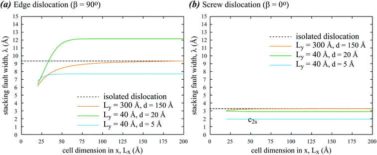 |
| | Fig. 4 Stacking fault width λ of (a) edge and (b) screw dislocations as a function of x dimension Lx at different y dimensions and dipole lengths, Ly and d. | |
Fig. 4 indicates that stacking fault width λ is narrower for screw dislocation than for edge dislocation, and λ is sensitive to cell dimensions. When Lx, Ly, and d are all large, λ approaches the value for isolated dislocation as expected. When Lx is small, λ is small as it is limited by Lx/2. The sensitivity to Lx reduces when Lx increases, but the saturated λ still depends on Ly, d, and the dislocation type. Normally, it can be thought that the periodic boundary conditions would constrain dislocations. It is therefore surprising that for the edge dislocation, λ is larger than the value from isolated dislocation at relatively small values of Ly = 40 Å and d = 20 Å. This phenomenon is not observed for the screw dislocation results in Fig. 4(b). The complex relationships between λ and computational geometry present a warning to our past interpretations of dislocation dissociation under the periodic boundary conditions.
(D) Molecular dynamics validation of stacking fault width
Selected atomistic simulations are performed to validate the stacking fault width calculations. The methods developed previously5 are used to introduce dislocation dipoles in atomistic systems. Using the same aluminum interatomic potential as that used previously,5,8 and applying a zero-pressure NPT ensemble (i.e., number of atoms, pressure, and temperature are kept constant) with the periodic boundary conditions, molecular dynamics (MD) simulations are performed for 4 ns at 300 K. The structures are further relaxed using energy minimization. To ensure that dislocation does not randomly migrate during the MD simulations, the centre of mass of small regions above and below the dislocations is not allowed to shift. Four consecutive (111) planes near an edge and a screw dislocation, obtained from simulations at different Lx and Ly (d is taken at Ly/2), are shown in Fig. 5(a) and (b), where different colours indicate OVITO results of local structures (fcc for face-centred-cubic, hcp for hexagonally closely packed, and bcc for body centred cubic).9,10 Fig. 5(a) confirms that in the edge dislocation case, the stacking fault width at Lx ∼ 40 Å is narrower than that at Lx ∼ 200 Å, and the magnitudes of both widths are quite close to those shown in Fig. 4(a). Fig. 5(b) shows no hcp atoms that typically occur within the stacking faults. This means that the stacking fault width of the screw dislocation is narrower than that of the edge dislocation, which is also consistent with Fig. 4.
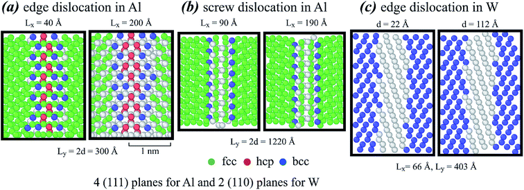 |
| | Fig. 5 Dislocation configurations obtained from atomistic simulations for (a) edge dislocation in aluminum, (b) screw dislocation in aluminum, and (c) edge dislocation in tungsten. | |
Aluminum has an fcc structure. Atomistic simulations are also performed for bcc tungsten using the embedded-atom method potential.11 Two consecutive (110) planes near an edge dislocation obtained from simulations at Lx = 66 Å and Ly = 403 Å and two different values of d = 22 and 112 Å are included in Fig. 5(c). Following the previous approach,5 we found that this potential gives lattice constant a = 3.1686 Å and shear modulus G = 1.0016 eV Å−3 at a chosen Poisson's ratio of ν = 0.3. Experiments indicated that tungsten has a stacking fault energy of γ = 0.03 eV Å−2.12 Based on these parameters, eqn (10) would give λ = ∼10–13 Å for the two cases shown in Fig. 5(c), which seems to be in good agreement.
3. Dislocation energies
(A) Previous works on dislocation energy
According to the previous works,5,6 the per unit length energy Γ for periodic dislocation arrays can be expressed as follows:| |
 | (12) |
where Ec and r0 are the core energy and core radius respectively, ΔEdis is the dissociation energy per unit length, and functions cue0(d), cus0(d), cue(d), cus(d) are expressed as follows:| |
 | (13) |
| |
 | (14) |
| |
 | (15) |
| |
 | (16) |
Like eqn (8), (9), (15) and (16) also converge rapidly, so that our choice of 100 summation terms is enough to ensure accurate results.5 The past works1–5 have not addressed the dissociation energy ΔEdis, which is the focus of the following section.
(B) Analytical expression for ΔEdis
Direct integration of stress and strain fields of all partials is challenging. Alternatively, dissociation energy ΔEdis can be calculated based on the work done when the blue dislocations in Fig. 1(b) are displaced from an initial location x = 0 to a final location x = λ. To avoid singularity at x = 0, we will derive the work from an initial location x = Lx/2 instead. This does not change the relative energy, but changes only the reference state from x = 0 to x = Lx/2.
In a per dislocation unit, we only consider the work done between a chosen blue dislocation (say, b0,0) and all the black dislocations in array. To displace any pair of blue and black dislocations from an initial x-spacing x1 to a final x-spacing x2 without changing the y-spacing y, the work done is  . Using eqn (1), we have the following:
| |
 | (17) |
We first calculate the total work done by the black dislocation row at y = 0 due to the displacement from x = Lx/2 to x = x. This work can be written as follows:
| |
 | (18) |
where
| |
 | (19) |
Note that eqn (19) essentially sums up ln(x22/x12) in a sequence of x1 = (i − 1) × Lx + Lx/2, x2 = (i − 1) × Lx + x, and x1 = −i × Lx + Lx/2, x2 = −i × Lx + x (i = 1, 2, …), and it has a closed-form solution. Next, we calculate the total work done by any vertical column of black dislocations (except the dislocation at y = 0). Assuming that the initial and final x-spacings between the blue dislocation and the black dislocation column are x1 and x2 respectively, this work can be written as follows:
| |
 | (20) |
By summing up eqn (17) in the similar y sequence as described above, we can find:
| |
 | (21) |
| |
 | (22) |
Eqn (21) and (22) have a closed-form solution:
| |
 | (23) |
| |
 | (24) |
The total work done by the entire black dislocation arrays, from initial partial separation distance Lx/2 to final separation distance x, can be expressed as follows:
| |
 | (25) |
Again, the summation in eqn (25) follows a similar sequence described above. Considering that energy has an opposite sign to work, and that the reference state of dissociation energy is undissociated dislocation (i.e., x = 0 rather than Lx/2), the dissociation energy as a function of partial separation distance x can then be simply expressed as follows:
| | |
ΔEdis(x) = −[w(x) − w(r0)]
| (26) |
Note that to avoid singularity, our reference state is taken as x = r0 rather than x = 0, where r0 is the dislocation core radius. Eqn (18)–(20) and (23)–(26) can be conveniently used to calculate the dissociation energy.
Since eqn (25) is not a closed form, we first explore its convergence. Based on the aluminum parameters cited above, ΔEdis(x) is calculated as a function of the number of summation terms N at fixed Ly = 2d = 420 Å, and the results are shown in Fig. 6(a)–(d) for four different sets of Lx and x. It can be seen that while the convergence rate increases when Lx is increased and x is decreased, the effect of x becomes more significant. Given that Ly = 2d = 420 Å, accurate results can be achieved without any summation terms in Fig. 6(a) at the small partial spacing x = 7 Å, despite that Lx = 20 Å is also small. If Lx is not too large, say 210 Å, and x is large, say 107 Å (the maximum x for a given Lx is Lx/2), then accurate results may require ∼100 summation terms, as shown in Fig. 6(c). Such a large partial spacing (or under the equilibrium condition, the stacking fault width), however, is unlikely to be encountered.
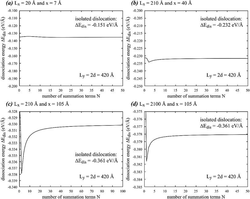 |
| | Fig. 6 Dissociation energy ΔEdis as a function of number of summation terms N at fixed y dimension Ly = 420 Å, dipole length d = 210 Å, and four different sets of x dimension Lx and partial spacing x of (a) Lx = 20 Å, x = 7 Å, (b) Lx = 210 Å, x = 40 Å, (c) Lx = 210 Å, x = 105 Å, and (d) Lx = 2100 Å, x = 105 Å. Note that results from periodic and isolated dislocations may differ. | |
The effect of x is a new finding as we have not thoroughly explored this in Fig. 2. Regardless, Fig. 6 confirms that our use of N = 100 is still extremely conservative for any practical stacking fault width.
(C) Comparison of dissociation energy with isolated dislocation
With the convenient methods and the aluminum parameters discussed above, we calculate dissociation energy as a function of partial spacing x using three different sets of geometric parameters. The results of these calculations are shown in Fig. 7(a) for Lx = 20 Å, Ly = 420 Å, d = 210 Å, Fig. 7(b) for Lx = 210 Å, Ly = 420 Å, d = 210 Å, and Fig. 7(c) for Lx = 210 Å, Ly = 42 Å, d = 21 Å. Additionally, we also calculate total dissociation energy ΔEdis + γx as a function of x using fixed Ly = 300 Å, d = 150 Å, and two different Lx values of 25 Å and 200 Å, where γ = 0.0083 eV Å−2 is the stacking fault energy. The results of this calculation are shown in Fig. 7(d). The corresponding results from isolated dislocations are included as black dash lines in Fig. 7(a)–(c), and as a thick red line in Fig. 7(d).
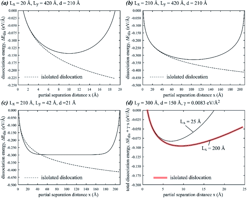 |
| | Fig. 7 Dissociation energy ΔEdis as a function of partial spacing x for (a) Lx = 20 Å, Ly = 420 Å, d = 210 Å, (b) Lx = 210 Å, Ly = 420 Å, d = 210 Å, and (c) Lx = 210 Å, Ly = 42 Å, d = 21 Å. Total dissociation energy ΔEdis + γx as a function of x for (d) Ly = 300 Å, d = 150 Å, γ = 0.0083 eV Å−2 and two different values Lx = 25 Å and Lx = 250 Å. | |
Fig. 7 indicates the negative dissociation energy, confirming that dissociation is energetically favorable. ΔEdis is symmetric with minimum at x = Lx/2, consistent with Fig. 3 that force drops to zero and is antisymmetric at x = Lx/2. Fig. 7 also indicates that ΔEdis obtained from periodic and isolated dislocations deviate significantly at x near Lx/2 but can be quite close for small x. Interestingly, ΔEdis for isolated dislocations can have both negative deviation as shown in Fig. 7(a) and (b) and positive deviation as shown in Fig. 7(c). The equilibrium stacking fault width, identified as λ ∼ 7 Å at Lx = 25 Å and λ ∼ 9 Å at Lx = 200 Å by the minimum energy point in Fig. 7(d), matches the corresponding results in Fig. 4. Interestingly, the ΔEdis + γx curve obtained for the cell parameters Ly = 300 Å, d = 150 Å, and Lx = 200 Å matches the corresponding curve from isolated dislocations at least for x ≤ 25 Å. For this particular case, the stacking fault width from periodic boundary conditions matches that for isolated dislocations, which is also consistent with Fig. 4. This observation is useful to guide the choice of computational cell that facilitates the calculation of stacking fault energy from the measurement of stacking fault width in simulations. However, it should be noted that in this particular case, the energy minimum is not very sharp, meaning that the stacking fault width observed in atomistic simulations is likely to have a large uncertainty margin.
4. Conclusions
We have developed useful expressions to calculate the dissociation thermodynamics of periodic dislocation dipoles in isotropic materials. The results indicated that periodic boundary conditions have complex influences on partial dislocation interaction forces, stacking fault widths, and dissociation energies. Depending on the system dimensions and dipole length, stacking fault width under the periodic conditions can be both above and below the value obtained from isolated dislocations. We anticipate that our expressions will impact future atomistic studies of dislocation properties. As one particular case, the best current method to calculate the dislocation core energy is to fit the total dislocation energy obtained from atomistic simulations to continuum models using the periodic boundary conditions. Such continuum models have not accounted for dislocation dissociation effects. By considering dislocation dissociation, our new development will result in more accurate dislocation core energy calculations.
Conflicts of interest
There are no conflicts of interest to declare.
Acknowledgements
Sandia National Laboratories is a multi-mission laboratory managed and operated by National Technology and Engineering Solutions of Sandia, LLC, a wholly owned subsidiary of Honeywell International, Inc., for the U.S. Department of Energy's National Nuclear Security Administration under contract DE-NA-0003525. The authors gratefully acknowledge research support from the U.S. Department of Energy, Office of Energy Efficiency and Renewable Energy, Hydrogen and Fuel Cell Technologies Office. The views expressed in the article do not necessarily represent the views of the U.S. Department of Energy or the United States Government.
References
- V. V. Bulatov and W. Cai, Computer Simulations of Dislocations, Oxford University Press, London, 2006 Search PubMed.
- W. Cai, V. V. Bulatov, J. Chang, J. Li and S. Yip, Philos. Mag., 2003, 83, 539 CrossRef CAS.
- W. Cai, V. V. Bulatov, J. Chang, J. Li and S. Yip, Phys. Rev. Lett., 2001, 86, 5727 CrossRef CAS.
- J. Li, C. Z. Wang, J. P. Chang, W. Cai, V. V. Bulatov, K. M. Ho and S. Yip, Phys. Rev. B, 2004, 70, 104113 CrossRef.
- X. W. Zhou, R. B. Sills, D. K. Ward and R. A. Karnesky, Phys. Rev. B, 2017, 95, 054112 CrossRef.
- X. W. Zhou, D. K. Ward, J. A. Zimmerman, J. L. Cruz-Campa, D. Zubia, J. E. Martin and F. van Swol, J. Mech. Phys. Solids, 2016, 91, 265 CrossRef CAS.
- D. Hull and D. J. Bacon, Introduction to dislocations, Butterworth-Heinemann, Oxford, 4th edn, 2001 Search PubMed.
- X. W. Zhou, D. K. Ward and M. E. Foster, J. Alloys Compd., 2016, 680, 752 CrossRef CAS.
- A. Stukowski, Modell. Simul. Mater. Sci. Eng., 2010, 18, 015012 CrossRef.
- A. Stukowski and K. Albe, Modell. Simul. Mater. Sci. Eng., 2010, 18, 085001 CrossRef.
- X. W. Zhou, R. A. Johnson and H. N. G. Wadley, Phys. Rev. B, 2004, 69, 144113 CrossRef.
- B. Pegel, Phys. Status Solidi, 1968, 28, 603 CrossRef CAS.
|
| This journal is © The Royal Society of Chemistry 2020 |
Click here to see how this site uses Cookies. View our privacy policy here.  Open Access Article

 . When a blue dislocation is separated from the black dislocation by x and y in the horizontal and vertical directions, the black dislocation will apply an x-component force to the blue dislocation:7


 is written as
  . The infinite summations in eqn (3) and (4) have closed-form solutions written as follows:


 . Using eqn (1), we have the following:


