 Open Access Article
An environment-friendly crosslinked binder endowing LiFePO4 electrode with structural integrity and long cycle life performance†
Lingzhu Zhaoa,
Zhipeng Suna,
Hongbing Zhanga,
Yuli Lic,
Yan Moa,
Feng Yu *ab and
Yong Chen
 *a
*a
aState Key Laboratory of Marine Resource Utilization in South China Sea, Hainan Provincial Key Laboratory of Research on Utilization of Si-Zr-Ti Resources, College of Materials Science and Engineering, Hainan University, Renmin Road No. 58, Haikou, 570228, PR China. E-mail: yuf@hainu.edu.cn; ychen2002@163.com
bKey Laboratory of Advanced Energy Materials Chemistry (Ministry of Education), College of Chemistry, Nankai University, Tianjin, 300071, PR China
cInstitution of Plastic Surgery, Weifang Medical University, Weifang 261042, P. R. China
First published on 11th August 2020
Abstract
Lithium iron phosphate (LiFePO4) is one of the most widely used cathode materials of lithium ion batteries. However, its commercial binder polyvinylidene fluoride (PVDF) is costly, less environmental-friendly and unstable during the long cycling process because of the weak van der Waals forces between the PVDF binder and electrode materials. Herein, an aqueous binder was designed using methacrylate-modified gelatin through UV photo-crosslinking. The crosslinked network and specific functional groups (carboxyl and amino) of the gelatin binder are superior in stabilizing the LiFePO4 electrode structure during long cycles by mitigating the formation of cracks and suppressing the detachment of electrode materials from the Al current collector. The LiFePO4 electrode with gelatin binder displays a high capacity of 140.3 mA h g−1 with 90.1% retention after 300 cycles at 0.5C, which are both superior to that of the PVDF binder (only 114.4 mA h g−1 and 74.8%). This work provides a promising binder to replace the commercial PVDF binder for practical application in energy storage systems.
1. Introduction
Lithium ion batteries (LIBs) based on the LiFePO4 cathode are regarded as a promising option for large-scale applications in transportation, computing and telecommunications because of its low cost, good safety and chemical stability.1,2 As a small component in the LiFePO4 cathode structure, the binder is utilized to bond the active material (LiFePO4) and conductive agents onto the metal current collector, and plays a vital role in the electrode processing and battery performances.3 A high-performing binder should have the ability to adhere the active material and conductive agents onto the current collector with good dispersion and stabilization to ensure the integrity of the electrode, and to build a good interconnected electric network among electrode materials so as to facilitate the diffusion of the lithium ion (Li+) and the electron (e−) transport in the electrode.4 As a conventional binder for the cathode electrodes in commercial LIBs, the polyvinylidene difluoride (PVDF) has good electrochemical stability and adhesion ability.5 Nevertheless, PVDF has some serious drawbacks, which could greatly restrict its potential application. First, it is quite costly and uses strongly polarized organic solvents, such as N-methyl pyrrolidone (NMP), which is volatile, toxic and expensive.6,7 Second, it has a high swelling property, and is more likely to dissolve into an organic carbonate-based electrolyte, leading to severe exfoliation of the particles and degradation of the electrode.8,9 In addition, its disposal in the end is a big problem. Subsequently, the LiFePO4 electrode based PVDF binder usually suffers from poor electrochemical performance (especially poor cycling stability) during the long cycling process due to the unstable electrode–electrolyte interface and structure degradation.10 Thus, new binders are needed urgently, exhibiting low cost, environment friendly and easy electrode processing and disposability, as well as good electrochemical performance.Producing a "greener" electrode makes it possible to develop greener and cost-effective LiBs.11 Recent studies have shown that the hydro-soluble and naturally derived polymers exhibit promising properties as binders for the cathode and anode, such as carboxymethyl cellulose (CMC),12,13 chitosan (CS)14 and alginate (Alg).15,16 For instance, Shiming Zhang first used CMC as a binder for the Li1.2Ni0.13Co0.13Mn0.54O2 cathode, and its cycling performance has been improved due to the good adhesive force between CMC and the aluminum (Al) current collector.12 The biomaterial chitosan has also been investigated as a binder for the LiFePO4 cathode by K. Prasanna et al.14 The results showed that the CS binder attained a higher discharge capacity of 159.4 mA h g−1 with a remarkable retention of 98.38% compared with the PVDF binder, which had a discharge capacity of 127.9 mA h g−1 and a capacity retention ratio of 85.13%.
However, most of these binders work by physical entanglement between the polymer chains and cathode or anode materials. Due to the linear chain features of these polymer binders, the active particles and conductive agents in the electrode tend to aggregate and be pushed away from each other during delithiation/lithiation processes, resulting in the broken electric contact, increased resistance of the electrode and poor electrochemical performance.17 Consequently, it was proposed in recent years to design the three-dimensional (3D) cross-linked binders to maintain the integrity of the electrodes.11 For example, Jean et al. synthesized an amphiphilic binder crosslinked by the Michael addition reaction for LiFePO4 cathodes. The crosslinked electrodes showed better stability for cycling performances than the PVDF binder, which showed a rapid depletion of the discharge capacity after 200 cycles at 25 °C (charge 0.25C and discharge 1C).18 These reported articles on 3D crosslinked binders can not only provide a robust chemical structure to sustain the integrity of the electrode, but also progress the cycle performance by restraining the exfoliation or rupture of active particles in the network.
Another inevitable drawback of the nature-derived polymer binders is that the insulated polymer chains could impede the lithium ions and electron transportation to some extent. To optimize the structure of the 3D crosslinked binders, an effective route is to introduce some functional groups or molecular segments that are beneficial to enhance the conductivity and transport of Li+ at the interface, such as ether functional groups similar to polyethylene oxide (PEO),19–21 lithium salinized polymer.22,23 For instance, Huang et al. designed an aqueous lithiated ionomer binder (PSBA-Li). The attached Li+ on the binder chains could help shorten the pathway of the free Li+ to the particles' surface and enhance the Li+ conductivity.24 Additionally, the introduction of some specific polar functional groups into the 3D crosslinked binder were proved to effectively enhance the transport of Li+ and e−.11 For instance, Zhang et al. prepared a double-helix-structure water-based binder consisting of abundant charged functional groups (hydroxyl and carboxylate), which were beneficial to wrap binder chains tightly on the surfaces of the particles and conductive additives, and to contribute a compact interconnected electric network.25 Therefore, preparing a binder with a 3D crosslinked structure containing special functional groups and molecular segments that can enhance the structural integrity, adhesion, and the conduction of Li+ or e−, is proposed as a crucial strategy.
Herein, we developed an aqueous environment-friendly gelatin binder (crosslinked by adding a crosslinker (PEGDA), short for polyethylene glycol diacrylate) for the LiFePO4 cathodes through the UV cross-linking method. Owing to large amounts of functional groups, such as amino and carboxyl groups in the gelatin backbone26 and ether linkage in the crosslinker PEGDA, this 3D network binder could not only maintain the uniform dispersion of active materials during continual cycling, but also help form interconnected conducting bridges between the active materials and binders in the electrode to promote the transport of Li+ and electrons. All of these factors help to keep the electrode structural integrity and stability, thus significantly improving the reversibility of the batteries based on the LiFePO4 cathode. Here, by using the gelatin as a novel binder, the LiFePO4 electrodes display superior electrochemical performance, indicating that this naturally derived binder is a promising candidate for a commercial PVDF binder in lithium batteries.
2. Materials and methods
2.1 Materials
Gelatin with a Bloom strength of 257, methacrylic anhydride (MA) and polyethylene glycol diacrylate (PEGDA, 400 g mol−1) were provided by Aladdin (Shanghai). PBS (pH = 7.4) was obtained from Solarbio (Shanghai). Ir2959 as a photointiator was purchased from Sigma Aldrich. The commercial LiFePO4 powders (D50 = 1.302 μm) and PVDF (1 × 10⁶ g mol−1) were supplied by Ke Lu De Co., Ltd., Shenzhen. KB (Akzo Nobel N.V., battery grade), Celgard 2300 type separator (Celgard, Inc, America) and the electrolyte (Gauss New Energy Technology Co., Ltd, Ningbo) were commercially obtained. The battery case (2025 coin-type) and lithium sheet were obtained from Ke Lu De Co., Ltd., Guangdong.2.2 Methods
![[thin space (1/6-em)]](https://www.rsc.org/images/entities/char_2009.gif) :
:![[thin space (1/6-em)]](https://www.rsc.org/images/entities/char_2009.gif) 1. The GMA (without adding PEGDA) was used as a control group since GMA can still form a crosslinked gel with Ir2959 due to the self-crosslinking process within the acrylate groups. The commercial binder PVDF here was also used as a blank control group. The binder gelatin samples with and without crosslinker PEGDA are labeled as GP and G in the text, respectively.
1. The GMA (without adding PEGDA) was used as a control group since GMA can still form a crosslinked gel with Ir2959 due to the self-crosslinking process within the acrylate groups. The commercial binder PVDF here was also used as a blank control group. The binder gelatin samples with and without crosslinker PEGDA are labeled as GP and G in the text, respectively.![[thin space (1/6-em)]](https://www.rsc.org/images/entities/char_2009.gif) :
:![[thin space (1/6-em)]](https://www.rsc.org/images/entities/char_2009.gif) 10
10![[thin space (1/6-em)]](https://www.rsc.org/images/entities/char_2009.gif) :
:![[thin space (1/6-em)]](https://www.rsc.org/images/entities/char_2009.gif) 10 (wt%), the prepared slurries were then coated on Al foils and exposed to UV light for a duration of 30 s. The crosslinked electrodes were punched to the round sheets (10 mm in diameter), and thereafter dried in vacuum at 110 °C for 12 h. A PVDF binder mixed with LiFePO4 and KB (LiFePO4/KB/PVDF = 8
10 (wt%), the prepared slurries were then coated on Al foils and exposed to UV light for a duration of 30 s. The crosslinked electrodes were punched to the round sheets (10 mm in diameter), and thereafter dried in vacuum at 110 °C for 12 h. A PVDF binder mixed with LiFePO4 and KB (LiFePO4/KB/PVDF = 8![[thin space (1/6-em)]](https://www.rsc.org/images/entities/char_2009.gif) :
:![[thin space (1/6-em)]](https://www.rsc.org/images/entities/char_2009.gif) 1
1![[thin space (1/6-em)]](https://www.rsc.org/images/entities/char_2009.gif) :
:![[thin space (1/6-em)]](https://www.rsc.org/images/entities/char_2009.gif) 1) was made as the control sample. The CR2025 coin-type half cells were fabricated in an Ar-filled glovebox with lithium metal as the counter and reference electrodes, Celgard 2300 as the separator, and 1 mol L−1 LiPF6 dissolved in dimethyl carbonate/ethylene carbonate (DMC/EC, 1
1) was made as the control sample. The CR2025 coin-type half cells were fabricated in an Ar-filled glovebox with lithium metal as the counter and reference electrodes, Celgard 2300 as the separator, and 1 mol L−1 LiPF6 dissolved in dimethyl carbonate/ethylene carbonate (DMC/EC, 1![[thin space (1/6-em)]](https://www.rsc.org/images/entities/char_2009.gif) :
:![[thin space (1/6-em)]](https://www.rsc.org/images/entities/char_2009.gif) 1 vol%) as the electrolyte. The electrodes with different binders were marked as GP, G and PVDF binders, respectively.
1 vol%) as the electrolyte. The electrodes with different binders were marked as GP, G and PVDF binders, respectively.![[thin space (1/6-em)]](https://www.rsc.org/images/entities/char_2009.gif) :
:![[thin space (1/6-em)]](https://www.rsc.org/images/entities/char_2009.gif) 1) at 25 °C for 48 h and weighed (W1) again after wiping the spare electrolyte on the surfaces with filter papers. The increased mass percent of the electrode films (W1 − W0) × 100%/W0 represented the swellability (S). The morphology of the electrode sheets was observed by SEM (PHENOM, PROX). XRD (Bruker AXS D2 PHASER) was conducted to reveal the structure of the prepared substrate using a Cu Kα radiation source at 40 kV and 100 mA. The scan covered the 2θ range of 10–50°. The cycling performances of the cells were assessed in the voltage range from 2.5 V to 4.2 V at 25 °C on a battery test system (LAND CT2001A) at 0.2C, 0.5C and 1C rate (1C = 170 mA g−1), respectively. Electrochemical impedance spectroscopy (EIS) was conducted on an electrochemical workstation (Biologic VSP-300) in the frequency range of 10 mHz to 1000 kHz with an amplitude modulation of 5 mV at room temperature.
1) at 25 °C for 48 h and weighed (W1) again after wiping the spare electrolyte on the surfaces with filter papers. The increased mass percent of the electrode films (W1 − W0) × 100%/W0 represented the swellability (S). The morphology of the electrode sheets was observed by SEM (PHENOM, PROX). XRD (Bruker AXS D2 PHASER) was conducted to reveal the structure of the prepared substrate using a Cu Kα radiation source at 40 kV and 100 mA. The scan covered the 2θ range of 10–50°. The cycling performances of the cells were assessed in the voltage range from 2.5 V to 4.2 V at 25 °C on a battery test system (LAND CT2001A) at 0.2C, 0.5C and 1C rate (1C = 170 mA g−1), respectively. Electrochemical impedance spectroscopy (EIS) was conducted on an electrochemical workstation (Biologic VSP-300) in the frequency range of 10 mHz to 1000 kHz with an amplitude modulation of 5 mV at room temperature.3. Results and discussion
3.1 Physicochemical property of the gelatin binder
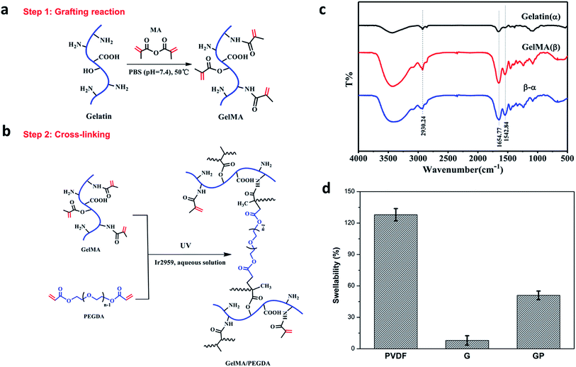
The GMA/PEGDA (GP) binder was designed and synthesized as shown in Fig. 1a and b. GMA was synthesized by the grafting reaction of gelatin with MA in PBS (pH = 7.4) at 50 °C. The methacrylate (CH3C(CH2)COO–) substitution groups were introduced on the reactive amine (NH2–) and hydroxyl (OH–) groups of the gelatin.27 As a result, GMA is capable of photo-initiating radical polymerization in the presence of an initiator (Ir2959) exposed to UV light.28 This polymerization can occur under mild conditions (in aqueous environments and at room temperature).29 GMA underwent the chemical crosslinking with or without the crosslinker PEGDA to constitute a favorable 3D crosslinked network structure. The gelatinization inversion experiment was conducted to clearly observe the phenomenon of the cross-linking (Fig. S1a†). The precursor solutions of G and GP were initially in the fluid state, and both changed into the solid state after UV polymerization. The gelatinization experiment could further confirm the success of graft reaction.The chemical structure of gelatin and GMA were characterized by Fourier transform infrared (FTIR) spectroscopy (Fig. 1c), and the curve (β-α) is the difference spectrum curve of gelatin (α) and GMA (β). The peak at 1654 cm−1 was correlated with the amide I bands, and could be attributed to the C![[double bond, length as m-dash]](https://www.rsc.org/images/entities/char_e001.gif) O stretching vibrations. The peak around 1542 cm−1 corresponded to the amide II bands that could be caused by the N–H bending vibrations and C–N stretching vibration coupling. In the difference spectrum curve, it was found that the amide characteristic peaks of GMA, especially the amide I bands at 1654 cm−1 and amide II bands at 1542 cm−1, were obviously stronger than the corresponding peak in pure gelatin, revealing the formation of amide (–CO–NH–) bonds by the reaction of gelatin and MA. In addition, the peak at 2930 cm−1 was also significantly strengthened. It was ascribed to the vibration of the methyl groups (CH3–) on MA. This indicated that the methyl acrylamide (CH3C(CH2)CONH–) groups were introduced into the gelatin molecule chain successfully.30
O stretching vibrations. The peak around 1542 cm−1 corresponded to the amide II bands that could be caused by the N–H bending vibrations and C–N stretching vibration coupling. In the difference spectrum curve, it was found that the amide characteristic peaks of GMA, especially the amide I bands at 1654 cm−1 and amide II bands at 1542 cm−1, were obviously stronger than the corresponding peak in pure gelatin, revealing the formation of amide (–CO–NH–) bonds by the reaction of gelatin and MA. In addition, the peak at 2930 cm−1 was also significantly strengthened. It was ascribed to the vibration of the methyl groups (CH3–) on MA. This indicated that the methyl acrylamide (CH3C(CH2)CONH–) groups were introduced into the gelatin molecule chain successfully.30
The miscibility of the G and GP binder solutions and active material was tested. It was observed that the mixed powder of LiFePO4/KB (8![[thin space (1/6-em)]](https://www.rsc.org/images/entities/char_2009.gif) :
:![[thin space (1/6-em)]](https://www.rsc.org/images/entities/char_2009.gif) 1 by mass) could easily be dispersed in the G and GP solutions, and form a homogeneous mixture without any precipitate after 5 days (Fig. S1b†). It is plausible that the unreacted amine groups and carboxyl groups on the molecular chain of GelMA is beneficial to the dispersion of materials.31 By contrast, it was difficult to retain the uniformity of LiFePO4/KB in deionized water (control group), and an obvious phase separation could be observed after mixing for a few minutes.
1 by mass) could easily be dispersed in the G and GP solutions, and form a homogeneous mixture without any precipitate after 5 days (Fig. S1b†). It is plausible that the unreacted amine groups and carboxyl groups on the molecular chain of GelMA is beneficial to the dispersion of materials.31 By contrast, it was difficult to retain the uniformity of LiFePO4/KB in deionized water (control group), and an obvious phase separation could be observed after mixing for a few minutes.
The swelling property of the electrode films in the organic electrolyte is shown in Fig. 1d. The crosslinked G and GP electrode films showed lower swellability value (8% and 51%, respectively) than the PVDF electrode film. The PVDF binder suffered from a higher swellability of 128%. As we know, the higher electrolyte uptake of the PVDF binder could improve the interface compatibility between the cathode and electrolyte. However, it could also reduce the molecular interaction between the binder and other electrode components due to softening and electrolyte solvation of the polymeric binders. As a result, the electronic conductive structure of the PVDF bound electrode might become partially loose or generate cracks due to the inordinate penetration of the electrolyte, which may finally result in capacity-fading and cycling life shortening.32 On the contrary, the GP crosslinked network with suitable electrolyte uptake could prevent the electrolyte solution from overly penetrating the electrode and ensure the integrity of the electrode. Compared with GP, G has relatively low wettability to the electrolyte, which would have a harmful effect on the electrochemical properties of the LiFePO4 cathode.
The crystal structures of the electrode substrates prepared by the PVDF, G and GP binders were observed by X-ray diffraction analysis (XRD) (Fig. S2†). The electrodes with PVDF, G and GP binders all showed the characteristic peaks at 17.90°, 23.90°, 25.57° and 31.94° corresponding to the (121), (220), (221) and (241) planes of the orthorhombic system, respectively. It was observed that the lattice constants correlated with the JCPDS card (39–1894; a = 8.24 Å; b = 16.48 Å and c = 10.39 Å). It was known from the XRD patterns that the crystalline structure of LiFePO4 would not be denatured by the PVDF, G and GP binders, compared with the XRD pattern of pure LiFePO4.33,34
The thermal stabilities of polymer binders have a vital effect on the electrochemical performances of LIBs, which were measured by thermogravimetric analysis (TGA) (Fig. S3†). The results showed that all G and GP binders had similar thermal behaviors, and there were two weight loss stages that existed. The first weight loss stage was at around 150 °C, which could be ascribed to the loss of unbound water. From Fig. S3,† it was clearly found that G had over 10 wt% weight loss in the first stage, while the weight loss of GP was less than 10 wt%. It meant that G possessed higher water absorption at room temperature. When the temperature was raised to over 300 °C, the weight loss was related to the overall decomposition of the G and GP crosslinked network. After adding PEGDA, the onset temperature increased to 345 °C, which was higher than that for G (285 °C). It could be interpreted that PEGDA helped improve the thermal stability of the crosslinked binder structure.
3.2 Electrochemical performance of the LiFePO4 electrode with different binders
The temporal evolution process of the impedance value with the storage time is shown in Fig. 2. The equivalent circuit is shown in Fig. 2D. The impedance spectra comprised a semicircle and a straight line that was in the high-frequency region and low-frequency region, respectively. They all showed a uniform increase in resistance (Rs) with the aging process in comparison to the cells made by the G, GP and PVDF binders. The increase of Rs was attributed to the formation of the passivation layer between the electrode and electrolyte with prolonged storage, indicating the compatibility between the electrode and electrolyte. The interface resistance typically stood for the resistance for ion migration between the electrode and electrolyte.35 In Fig. 2, the internal resistance of GP was the smallest, which was even lower than that for PVDF, and G without PEGDA possessed the largest Rs. This meant that G had poor interfacial compatibility with the electrolyte. This result was attributed to the poor wettability property of the G binder in the liquid electrolyte, as showed in Fig. 1d. However, for the GP binder, it possessed good interfacial contact and the lowest resistance because of the appropriate electrolyte affinity and abundant ether linkages of PEGDA. This was beneficial for wettability and lithium ion transporting. The PVDF binder possessed the highest electrolyte uptake, but its Rs was even higher than that for GP. This suggested that both good electrolyte wettability and proper lithium ion transporting molecular segments played a key role in reducing the interfacial resistance.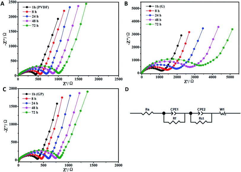 | ||
| Fig. 2 EIS obtained based on the temporal evolution for the LiFePO4 electrodes prepared using different binders. (A) PVDF, (B) G and (C) GP. (D) The equivalent circuit. | ||
In order to further prove the lithium ion transporting function of the GP binder, the lithium ion diffusion coefficient (DLi+) of the electrodes with different binders (PVDF, G and GP) was calculated from the formula as follows:36
 | (1) |
 | (2) |
![[thin space (1/6-em)]](https://www.rsc.org/images/entities/char_2009.gif) 500C mol−1 and 8.314 J K−1 mol−1, respectively. A is the electrode area, which is 0.785 × 10⁻⁴ m2, n is 1, T is 298 K, C can be calculated from the density and the molecular weight of the materials synthesized by different methods, which is 7.69 × 10³ mol m−3.
500C mol−1 and 8.314 J K−1 mol−1, respectively. A is the electrode area, which is 0.785 × 10⁻⁴ m2, n is 1, T is 298 K, C can be calculated from the density and the molecular weight of the materials synthesized by different methods, which is 7.69 × 10³ mol m−3.
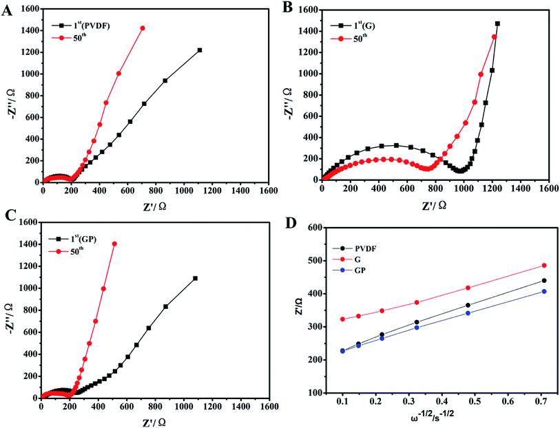
Fig. 3 displays the EIS of the electrodes with different binders. The interfacial resistances at the 1st and 50th cycles for binders PVDF, G and GP are clearly shown in Fig. 3A–C. It consisted of a semicircle and a straight line that was in the medium-frequency region and low-frequency region, respectively. The straight line in the low-frequency region is related to the lithium ion diffusion in the cathode. Depending on the slope of the straight line and combining the data shown in Fig. 3D, G had the lowest DLi+ value of 1.189 × 10⁻¹² cm2 s−1. GP had the highest value of 2.422 × 10⁻¹² cm2 s−1, which was higher than that of PVDF (1.983 × 10⁻¹² cm2 s−1). This result further suggested that the introduction of the crosslinker PEGDA could improve the lithium ion diffusion in the LiFePO4 cathode. The ether-oxygen (–C–O–) structure in PEGDA was proved to enhance Li+ migration and conductivity through the continually coordinating and dissociating reaction between the ether linkage and Li+.37
As we know, the higher lithium ion diffusion coefficient will lead to superior rate and cycle performances, especially at high current density. To evaluate the effect of the GP binder on the electrochemical performance of the electrodes, galvanostatic charge–discharge and cycling performance tests of half-cell configurations were observed in the voltage range of 2.5–4.2 V at different current densities.
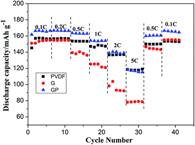
The cycling characteristics at different rates are shown in Fig. 4. It is interesting to note that the discharge capacity of GP was always superior to PVDF at different rates from 0.1C to 2C. Even at 5C, the discharge capacity of GP was maintained at a high level of about 120 mA h g−1, which was comparable with that of the PVDF binder. Here, the G binder showed the worst rate property, especially at high current density. This was because of the poor electrolyte wettability and the brittle structure of pure gelatin, which limited the lithium ion migration and transport, both in the LiFePO4 cathode and the electrode–electrolyte interface.
The cycle performance of the LiFePO4 cathode with different binders at 0.2C, 0.5C and 1C was carefully observed, and is shown in Fig. 5.
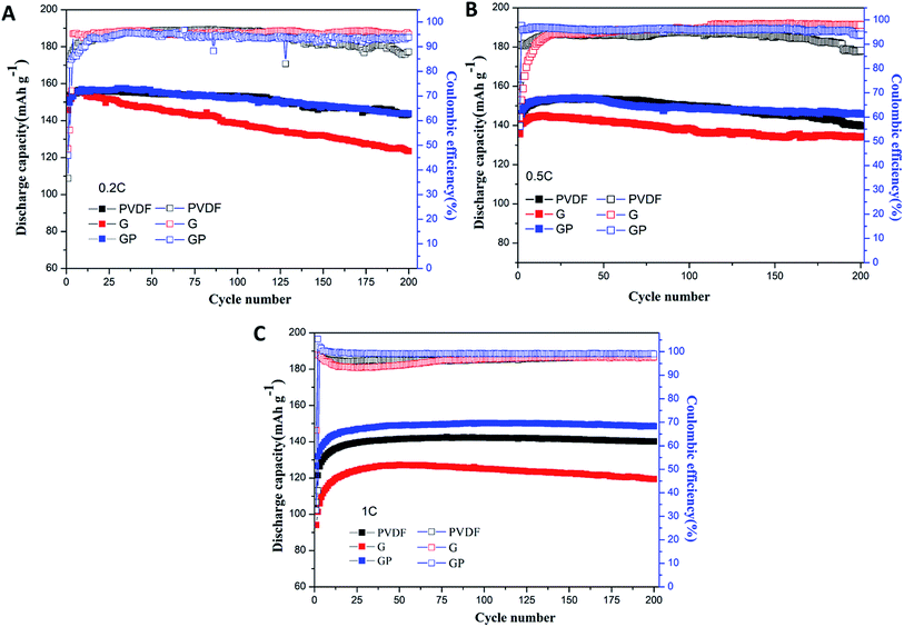 | ||
| Fig. 5 Cycling performances of the LiFePO4 cathode with PVDF, G and GP binders at different rates of 0.2C (A), 0.5C (B) and 1C (C). | ||
Fig. 5A shows the discharge and coulombic efficiency curves of the LiFePO4 electrodes using binders PVDF, G and GP at 0.2C at 25 °C. For the PVDF electrode, a discharge capacity of 143.6 mA h g−1 with 93.4% retention was obtained after 200 cycles. GP electrodes delivered the slightly higher discharge capacity of 143.8 mA h g−1 with a capacity retention of 94.8%. It suggested that there was no significant difference between GP and PVDF at 0.2C. However, the electrode with G showed a lower capacity value of 123.5 mA h g−1 with a low capacity retention of 84.7% after 200 cycles, which was much lower than that of PVDF. This result could be attributed to the increased internal resistance and decreased ionic diffusion coefficient for G in comparison to PVDF. The initial and final coulombic efficiencies after 200 cycles are also displayed in Fig. 5A. The GP electrode exhibited higher initial coulombic efficiency (45.86%) than the PVDF based electrode (36.52%). Similarly, the final coulombic efficiency of GP (93.72%) was also higher than that of PVDF (87.89%). The details of the cycling performance at high rates of 0.5C and 1C are also discussed. Here, from Fig. 5B and C, it could be seen that the specific discharge capacity of the cathodes with PVDF, G and GP binders all increased gradually during the first 15 cycles. This phenomenon was possibly caused by the activation process of the electrode materials.
At 0.5C, the 200th discharge capacity of PVDF was 139.8 mA h g−1 and the capacity retention was 91.4% after 200 cycles. The GP electrode possessed the higher discharge capacity of 145.9 mA h g−1 with a high capacity retention of 95% compared with PVDF. The cycling advantages of GP was much more significant than PVDF and G at the high rate of 1C, as shown in Fig. 5C. The 200th discharge capacity of GP was 148.6 mA h g−1, which is definitely higher than that of the PVDF and G binders. There was hardly a capacity fading found after 200 cycles.
Even though the capacity retention, coulombic efficiency and the performance stability of GP were better than that of PVDF, the PVDF binder was still stable and displayed a relatively high capacity retention of about 91% even over 200 cycles at high rates. Therefore, longer cycles were used to further analyze the difference between the GP binder and PVDF binder. As shown in Fig. 6, the PVDF based electrode showed serious capacity fading, only 114.4 mA h g−1 after 300 cycles with a low capacity retention of 74.8% and bad coulombic efficiency of 61.86%. In contrast, the GP based electrode displayed less capacity fading and still delivered a high capacity of 140.3 mA h g−1 after 300 cycles, with a good capacity retention of 90.1% and excellent coulombic efficiency of 96.31%. From the 300 cycle cycling performance between GP and PVDF, it could be concluded that PVDF as a commercial binder could keep its outstanding cycling property before 200 cycles. It would face a severe capacity fading after 200 cycles, and could only have a capacity retention of 74.8%. The GP binder could obtain excellent cycling performances compared to PVDF. The reason for the capacity fading of PVDF after 200 cycles was also explored in this work. Fig. S4† shows the charge–discharge profiles of the LiFePO4/PVDF and LiFePO4/GP electrodes at various cycle numbers in the voltage range between 2.5 V and 4.2 V at 0.5C. During the charge and discharge process, the cathode with the PVDF binder demonstrated a flat voltage plateau at 3.53 V and 3.31 V for the first cycle. It was observed to be constant for the 10th, 50th, 100th, and 300th cycles, where it possessed a stable polarization value at around 0.22 V, as shown in Fig. S4A.† For the GP binder, the charge and discharge flat voltage plateau was at 3.58 V and 3.26 V for the first cycle with a potential value of 0.32 V. Furthermore, the flat voltage plateau was at about 3.60 V and 3.21 V. The polarization value was changed from 0.32 V at the first cycle to 0.39 V at the 300th cycle. From the data, it could be concluded that cathodes with the PVDF binder suffered from the lower electrochemical polarization. Therefore, the electrochemical polarization was not the main reason for the poor cycling performance of the PVDF binder compared with GP. However, from Fig. S4,† we found that the GP binder and PVDF binder both suffered from the side reaction in the first cycle. Therefore, we guess that the irreversible consumption of the lithium ion in the first cycle may be caused by the additives in the liquid electrolyte, which could improve the formation of a stable passivation layer at the interface. That is the reason for the low coulombic efficiency in the first cycle.
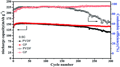 | ||
| Fig. 6 Cycling performance of the LiFePO4 cathode at 0.5C with the PVDF and GP binders, respectively. | ||
We suspected that the outstanding cycling properties of the GP binder could be ascribed to its integrated structure even after long cycles. In order to further illuminate the beneficial effect of the structure on the cycling stability, the surface morphology of the LiFePO4/PVDF and LiFePO4/GP electrodes before and after long cycles was observed by scanning electron microscopy (SEM), as shown in Fig. 7. It could be seen that the surface morphologies appeared to be smooth for the pristine electrodes with both binders before the cycling test, as shown in Fig. 7a–c. However, after 200 cycles, the PVDF based electrode presented obvious cracks, as shown in Fig. 7d. On the contrary, the GP based electrode displayed no obvious fractures. The SEM images proved that the GP binder with crosslinked structure could maintain the structural integrity of the electrode, and was beneficial to the long cycling performances.
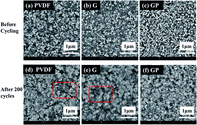 | ||
| Fig. 7 SEM micrographs of the LiFePO4 electrodes with different binders before (a–c) and after 200 cycles (d–f). | ||
Fig. S5(a) and (b)† showed the optical images of the cycled electrodes with PVDF and GP binders after 300 cycles at 0.5C. The electrode with PVDF binder suffered from severe particle pulverization. Furthermore, active material particles seriously peeled off from the Al current collector, and diffused outward and deposited onto the separator. This could lead to poor cycling stability, especially at high rates. However, no obvious failure was found in the GP based electrode. Thus, we could obtain the direct reasons why the GP binder exhibited much more excellent cycling performance than PVDF. The crosslinked GP binder could prevent the electrode from crack formation and the shedding of active particles.
The mechanism of the GP binder enhancing the long life cycle property of LIBs could be explained via the following Scheme 1. Briefly, the crosslinked structure itself and the multiple chemical interactions of the binder with the active particles, of the binder with the collector, and even of the binder with Li+ both play an important role in improving the electrochemical properties of LIBs. On the one hand, the crosslinked structure of the binder is necessary to maintain the integrity of the electrodes. In this study, the GP binder was cross-linked in situ via UV-curing during LiFePO4 electrode fabrication. The strong 3D crosslinked network built by the GP binder enabled the uniform formation of a coating layer on the surfaces of the LiFePO4 and KB particles. The formed coating layer could make the contact between the adjacent LiFePO4 and KB particles closer, which would help reduce the resistance among particles to improve the electron transfer efficiency.38,39 Meanwhile, the crosslinked GP network could limit the movement of active particles so that they sustained the pristine morphology. In addition, the crosslinked structure could limit the over-uptake of electrolyte during the extensive cycling process, which could be conductive to the stability of the electrode structure. By contrast, the PVDF binder without a crosslinked structure would become loose and finally lead to disaggregation during the repeated delithiation/lithiation processes, as shown in the SEM images after 200 cycles.
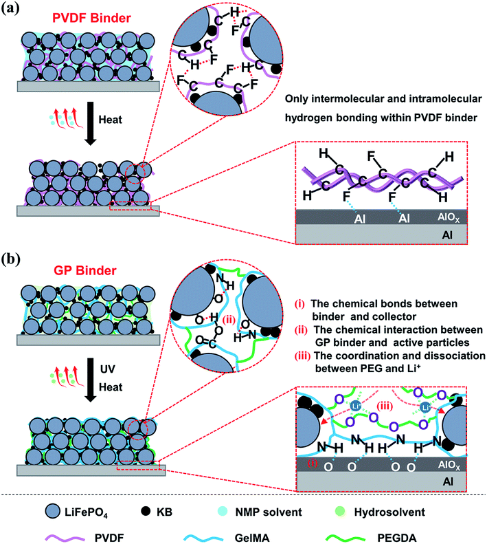 | ||
| Scheme 1 Graphical illustrations of the preparation and binding mechanisms of the LiFePO4 electrodes using (a) PVDF and (b) GP as the binder. | ||
On the other hand, the chemical interactions among the binder, active particles and collector is another essential factor for the long life cycle of LIBs. (1) The chemical bonds between the binder and collector enable the excellent adhesion property, which could significantly suppress the electrode material exfoliation. As shown in Scheme 1b, the remaining amino and carboxyl groups in the GP binder could form hydrogen bonds with the Al foil current collector, which enables the active material particles and conductive agents tightly bonding onto the Al foil.40 In contrast, the functions of the PVDF binder are based on weak van der Waals interaction. This leads to the poor adhesion of the electrode film onto the current collector that could affect the electrochemical performance, as shown in Scheme 1a. (2) The chemical interaction between GP binder and LiFePO4/KB particles plays a key role in the integrity of electrode. The strong hydrogen bonding interaction between the GP binder and LiFePO4/KB particles enables the GP binder to tightly wrap the LiFePO4/KB particles to decrease the polarization of the electrode materials, which could guarantee a highly uniform distribution of the electrode materials, as shown in Scheme 1b. However, the PVDF binder often tends to intermolecular and intramolecular agglomeration due to its structure, leading to conduction failure and electrode exfoliation.13 (3) The coordination and dissociation between the ether linkages existed in the PEGDA chain, and Li+ is another key factor to promote the migration of Li+ in the electrode. It has been reported that solid polymer electrolytes based on PEO can effectively transfer Li+ due to the lone pair electrons on the oxygen of the ether groups, which exists because of the coordination/dissociation interaction with Li+, and consequently forms abundant complexation sites. The complex Li+ can move assisted by these complexation sites as the segmental motion of the polymer matrix.41 In summary, the crosslinked structure of the GP binder and the multiple chemical interactions among the electrode components endow LIBs with superior electrochemical properties over the commercial PVDF binder.
4. Conclusion
In this paper, an aqueous UV-crosslinked GP as a LiFePO4 cathode binder was designed. By comparing with a commercial PVDF binder, the crosslinked GP binder displayed significantly improved electrochemical performance with high reversible capacity, especially at high rate. Most importantly, the GP binder showed superior ability in stabilizing the LiFePO4 electrode structure during 300 cycles. This was achieved by mitigating the formation of cracks and suppressing the electrode material detachment from the Al current collector, ensuring the electric contact ability. Moreover, taking the facile and ecofriendly fabrication into account, GP as a water-soluble and cross-linkable binder is safer, greener and cheaper than the PVDF binder systems based on organic solvents. This aqueous and UV-crosslinked gelatin is a promising binder for LiFePO4 cathodes of commercial Li-ion batteries, and may also be extended for the manufacturing of electrodes based on other materials.Conflicts of interest
There are no conflicts to declare.Acknowledgements
The authors express thanks for support to the Basic and Applying Basic Research Project of Hainan Province for High-level Talent (Grant No. 2019RC038), National Science Foundation of China (Grant No. 21965012), Hainan Provincial Natural Science Foundation of China (Grant No. 2018CXTD332 and HD-SYSZX-201802), Science and Technology Development Special Fund Project (ZY2018HN09-3) and the Scientific Research Start-up Foundation of Hainan University (Grant No. kyqd1568).References
- X. Zhang, P. N. Ross, R. Kostecki, F. Kong, S. Sloop, J. B. Kerr, K. Striebel, E. J. Cairns and F. McLarnon, J. Electrochem. Soc., 2001, 148(5), A463–A470 CrossRef CAS
.
- Y. Wang, P. He and H. Zhou, Energy Environ. Sci., 2011, 4, 805–817 RSC
.
- H. Zheng, R. Yang, G. Liu, X. Song and V. S. Battaglia, J. Phys. Chem. C, 2012, 116, 4875–4882 CrossRef CAS
.
- J.-T. Li, Z.-Y. Wu, Y.-Q. Lu, Y. Zhou, Q.-S. Huang, L. Huang and S.-G. Sun, Adv. Energy Mater., 2017, 7, 1701185 CrossRef
.
- Z. Zhang, T. Zeng, C. Qu, H. Lu, M. Jia, Y. Lai and J. Li, Electrochim. Acta, 2012, 80, 440–444 CrossRef CAS
.
- N. Loeffler, J. von Zamory, N. Laszczynski, I. Doberdo, G.-T. Kim and S. Passerini, J. Power Sources, 2014, 248, 915–922 CrossRef CAS
.
- I. Doberdò, N. Löffler, N. Laszczynski, D. Cericola, N. Penazzi, S. Bodoardo, G.-T. Kim and S. Passerini, J. Power Sources, 2014, 248, 1000–1006 CrossRef
.
- Z. Zhang, T. Zeng, Y. Lai, M. Jia and J. Li, J. Power Sources, 2014, 247, 1–8 CrossRef CAS
.
- S. Zhang and T. Jow, J. Power Sources, 2002, 109, 422–426 CrossRef CAS
.
- A. Guerfi, M. Kaneko, M. Petitclerc, M. Mori and K. Zaghib, J. Power Sources, 2007, 163, 1047–1052 CrossRef CAS
.
- Y. Shi, X. Zhou and G. Yu, Acc. Chem. Res., 2017, 50, 2642–2652 CrossRef CAS PubMed
.
- S. Zhang, H. Gu, H. Pan, S. Yang, W. Du, X. Li, M. Gao, Y. Liu, M. Zhu, L. Ouyang, D. Jian and F. Pan, Adv. Energy Mater., 2016, 7, 1601066 CrossRef
.
- Z. Chen, G.-T. Kim, D. Chao, N. Loeffler, M. Copley, J. Lin, Z. Shen and S. Passerini, J. Power Sources, 2017, 372, 180–187 CrossRef CAS
.
- K. Prasanna, T. Subburaj, Y. N. Jo, W. J. Lee and C. W. Lee, ACS Appl. Mater. Interfaces, 2015, 7, 7884–7890 CrossRef CAS PubMed
.
- J. Liu, Q. Zhang, Z. Y. Wu, J. H. Wu, J. T. Li, L. Huang and S. G. Sun, Chem. Commun., 2014, 50, 6386–6389 RSC
.
- Z.-Y. Wu, L. Deng, J.-T. Li, Q.-S. Huang, Y.-Q. Lu, J. Liu, T. Zhang, L. Huang and S.-G. Sun, Electrochim. Acta, 2017, 245, 371–378 CrossRef CAS
.
- X. Yu, H. Yang, H. Meng, Y. Sun, J. Zheng, D. Ma and X. Xu, ACS Appl. Mater. Interfaces, 2015, 7, 15961–15967 CrossRef CAS PubMed
.
- J.-C. Daigle, F. Barray, C. Gagnon, D. Clément, P. Hovington, H. Demers, A. Guerfi and K. Zaghib, J. Power Sources, 2019, 415, 172–178 CrossRef CAS
.
- W. Zeng, L. Wang, X. Peng, T. Liu, Y. Jiang, F. Qin, L. Hu, P. K. Chu, K. Huo and Y. Zhou, Adv. Energy Mater., 2018, 8, 1702314 CrossRef
.
- D. Yao, Y. Yang, Y. Deng and C. Wang, J. Power Sources, 2018, 379, 26–32 CrossRef CAS
.
- T. Munaoka, X. Yan, J. Lopez, J. W. F. To, J. Park, J. B. H. Tok, Y. Cui and Z. Bao, Adv. Energy Mater., 2018, 8, 1703138 CrossRef
.
- N. P. W. Pieczonka, V. Borgel, B. Ziv, N. Leifer, V. Dargel, D. Aurbach, J.-H. Kim, Z. Liu, X. Huang, S. A. Krachkovskiy, G. R. Goward, I. Halalay, B. R. Powell and A. Manthiram, Adv. Energy Mater., 2015, 5, 1501008 CrossRef
.
- L. Qiu, Z. Shao, D. Wang, W. Wang, F. Wang and J. Wang, Carbohydr. Polym., 2014, 111, 588–591 CrossRef CAS PubMed
.
- S. Huang, J. Ren, R. Liu, Y. Bai, X. Li, Y. Huang, M. Yue, X. He and G. Yuan, ACS Sustainable Chem. Eng., 2018, 6, 12650–12657 CrossRef CAS
.
- G. Zhang, B. Qiu, Y. Xia, X. Wang, Q. Gu, Y. Jiang, Z. He and Z. Liu, J. Power Sources, 2019, 420, 29–37 CrossRef CAS
.
- J. Sun, Y. Huang, W. Wang, Z. Yu, A. Wang and K. Yuan, Electrochim. Acta, 2008, 53, 7084–7088 CrossRef CAS
.
- A. Van Den Bulcke, B. Bogdanov, N. De Rooze, E. Schacht, M. Cornelissen and H. Berghmans, Biomacromolecules, 2000, 1, 31–38 CrossRef CAS PubMed
.
- J. A. Benton, C. A. DeForest, V. Vivekanandan and K. S. Anseth, Tissue Eng., Part A, 2009, 15, 3221–3230 CrossRef CAS PubMed
.
- J. W. Nichol, S. T. Koshy, H. Bae, C. M. Hwang, S. Yamanlar and A. Khademhosseini, Biomaterials, 2010, 31, 5536–5544 CrossRef CAS PubMed
.
- S. Bertlein, G. Brown, K. S. Lim, T. Jungst, T. Boeck, T. Blunk, J. Tessmar, G. J. Hooper, T. B. F. Woodfield and J. Groll, Adv. Mater., 2017, 29, 1703404 CrossRef PubMed
.
- N. Akhtar, H. Shao, F. Ai, Y. Guan, Q. Peng, H. Zhang, W. Wang, A. Wang, B. Jiang and Y. Huang, Electrochim. Acta, 2018, 282, 758–766 CrossRef CAS
.
- S. Komaba, K. Shimomura, N. Yabuuchi, T. Ozeki, H. Yui and K. Konno, J. Phys. Chem. C, 2011, 115, 13487–13495 CrossRef CAS
.
- H. Fang, G. Liang, L. Zhao, T. Wallace, H. Arava, L.-L. Zhang, A. Ignatov and M. C. Croft, J. Electrochem. Soc., 2013, 160, A3148–A3152 CrossRef CAS
.
- X. Qin, X. Wang, J. Xie and L. Wen, J. Mater. Chem., 2011, 21, 12444–12448 RSC
.
- P. L. Moss, G. Au, E. J. Plichta and J. P. Zheng, J. Power Sources, 2009, 189, 66–71 CrossRef CAS
.
- X. Wang, H. Hao, J. Liu, T. Huang and A. Yu, Electrochim. Acta, 2011, 56, 4065–4069 CrossRef CAS
.
- W. Fan, N. W. Li, X. Zhang, S. Zhao, R. Cao, Y. Yin, Y. Xing, J. Wang, Y. G. Guo and C. Li, Adv. Sci., 2018, 5, 1800559 CrossRef PubMed
.
- H. Q. Pham, G. Kim, H. M. Jung and S.-W. Song, Adv. Funct. Mater., 2018, 28, 1704690 CrossRef
.
- J. Sun, X. Ren, Z. Li, W. Tian, Y. Zheng, L. Wang and G. Liang, J. Alloys Compd., 2019, 783, 379–386 CrossRef CAS
.
- Y.-H. Lee, J. Min, K. Lee, S. Kim, S. H. Park and J. W. Choi, Adv. Energy Mater., 2017, 7, 1602147 CrossRef
.
- J. Liu, Q. Zhang, T. Zhang, J.-T. Li, L. Huang and S.-G. Sun, Adv. Funct. Mater., 2015, 25, 3599–3605 CrossRef CAS
.
Footnote |
| † Electronic supplementary information (ESI) available. See DOI: 10.1039/d0ra05095d |
| This journal is © The Royal Society of Chemistry 2020 |

