 Open Access Article
Crystallization of well-defined anatase nanoparticles in SBA-15 for the photocatalytic decomposition of acetic acid†
Kasimanat (Guy) Vibulyaseak a,
Bunsho Ohtani
 b and
Makoto Ogawa
 *a
*a
aSchool of Energy Science and Engineering, Vidyasirimedhi Institute of Science and Technology (VISTEC), 555 Moo 1 Payupnai, Wangchan, Rayong 21210, Thailand. E-mail: makoto.ogawa@vistec.ac.th
bInstitute for Catalysis, Hokkaido University, Sapporo 001-0021, Japan
First published on 1st September 2020
Abstract
Anatase nanoparticles with a size of ca. 5 nm were prepared in mesoporous silica (SBA-15 with the pore diameter of 6 nm) by impregnation of the precursor derived from titanium tetraisopropoxide and subsequent heat treatment in air. The mesoporous structure of the anatase–silica hybrid and the size of the anatase particles were kept unchanged during the crystallization of anatase at 200–600 °C. The hybrids were applied as a photocatalyst for the decomposition of acetic acid in water under UV irradiation to find the heat treatment over 400 °C led to higher efficiency of the reaction (45–55 μmol h−1 of carbon-dioxide production) over the samples heated at temperatures lower than 300 °C (3–14 μmol h−1 of carbon-dioxide production).
1 Introduction
Nanoparticles supported in porous solids are an important class of materials especially for application in catalysts.1 Mesoporous silicas (MPSs) have been used as the supports to immobilize various kinds of nanoparticles to construct hybrid catalysts, taking advantage of such characteristic features of MPSs, such as well-defined and variable pore shape and size, chemical and thermal stability, and surface reactivity due to silanol groups on the pore surface for the concentration and diffusion of substrates.2,3 Titanium dioxide (TiO2) is the species studied most extensively to be immobilized in MPSs and the catalysts' applications of the TiO2–MPS hybrids have been reported so far.4,5 The shape and size of the particles as well as their location in MPSs are key factors, so that the TiO2 species have been immobilized in MPSs in such different states as isolated molecular species and oxide nanoparticles in the silica wall and on the mesopores.6–21 Though the size-controlled synthesis of TiO2 particles has been a topic of interest in materials chemistry to adapt the wide range of applications of TiO2 and to optimize the materials' performances, size-controlled synthesis of TiO2 using MPSs as templates is still challenging.Well-defined anatase nanoparticles (precise size-control and narrow particle size distribution) are expected to obtain from the well-defined porous structure of the MPS template. There are many papers on the preparation of anatase in MPSs and the uses as photocatalysts, while the sizes and the locations of the anatase particles in the pores/on the external surface of the MPS particles are not precisely control resulting the broad particle size distribution of the anatase particles.7 The optimization of the crystallization temperature of anatase in MPS have been reported where the size of the anatase particle and the porosity of the hybrids changed by increasing the crystallization temperature, which were probably due to the growth of the anatase particles located on the external surface of the MPS particles during the heat treatment.18–21 The changes in the size of the anatase and the porosity of the hybrids makes the comparative evaluation of the photocatalysts' performances difficult. The photocatalytic performance of the hybrids is suppressed by the decrease of the surface area of the anatase nanoparticles due to the particles' aggregation/fusion, which block the pore entrance for the adsorption/diffusion of the reactants in the pore channels.
In the present paper, we report a precise syntheses of hybrids composed of a MPS, SBA-15, and well-defined anatase nanoparticles exclusively in the mesopores and the application of the hybrids as photocatalysts using the decomposition of acetic acid as a model reaction. The size of the anatase nanoparticles (5 nm) was controlled by the pore size (6 nm) of the SBA-15. The size distribution of the anatase nanoparticles was discussed from the UV-vis diffuse reflectance spectra to be narrower than the anatase particles prepared in SBA-15 reported so far. The role of a mesoporous silica to suppress the aggregation/fusion of the anatase particles during the crystallization at high temperatures was examined. Thanks to the precise immobilization of the anatase nanoparticles in the mesopores, the size of the anatase particles and the porosity of the SBA-15–anatase hybrids were keeping unchanged by increasing the crystallization temperature.
2 Experimental details
2.1 Materials
Tetraethyl orthosilicate (TEOS), titanium tetraisopropoxide (TTIP), poly(ethylene glycol)-block-poly(propylene glycol)-block-poly(ethylene glycol) (Pluronic P123), and isopropyl alcohol (IPA) were purchased from Aldrich. Hydrochloric acid (HCl) was purchased from Tokyo Chemical Industry Co. All of the reagents were used without further purification. Water was purified by using the Milli-Q system (>18 MΩ cm, Millipore).2.2 Synthesis of SBA-15
SBA-15 was synthesized by the reported method.22 Deionized water (30 g) was mixed with 2 mol L−1 aqueous solution of HCl (120 g) in the screw Pyrex glass container (250 mL) with the plastic cap, then Pluronic P123 (4.0 g) was added. The mixture was magnetically stirring at 35 °C until the clear solution was obtained. Then, TEOS (8.5 g) was added into the solution under magnetic stirring at 35 °C and stirred furtherly for 20 h. The mixture was transfer to the teflon-lined autoclave (250 mL) and heated at the heating rate of 10 °C min−1 to 100 °C and kept for 24 h without stirring. The solid product was collected by centrifugation at 4000 rpm for 15 min and washed with the deionized water. The washing process was repeated for 5 times and the product was air dried at 25 °C overnight. The sample was calcined by heating from 25 to 500 °C for 8 h and kept at 500 °C for 6 h to remove P123 completely.2.3 Preparation of anatase in the mesopore
The incorporation of anatase in the mesopore of SBA-15 is based on the preferential impregnation of TTIP into the pore and subsequent heat treatment as reported previously.23,24 TTIP was mixed with IPA and the mixture was sonicated for 15 min by to obtain the homogenous transparent solution. The volume ratio of TTIP:IPA was designed as 1![[thin space (1/6-em)]](https://www.rsc.org/images/entities/char_2009.gif) :
:![[thin space (1/6-em)]](https://www.rsc.org/images/entities/char_2009.gif) 8 to keep the remaining pore space after the removal of IPA after the heat treatment.24 SBA-15 was added in a 2-neck round bottom flask where the neck was connected to an oil-sealed rotary vacuum pump through a glass valve and another neck was closed with a rubber septum. The SBA-15 was dehydrated at 120 °C for 3 h under the reduced pressure (6.7 × 10⁻⁶ bar) and cooled down to 25 °C under the reduced pressure. After that, the valve was closed and TTIP solution (18 mL) was added to the dehydrated SBA-15 (1 g) by using syringe injected through the rubber septum, then the mixture was magnetically stirred for 24 h at 25 °C under the reduced pressure. The volume of TTIP solution (18 mL) was designated to excess the amount of SBA-15 powder (1 g). The solid product was collected by centrifugation at 4000 rpm for 15 min. The product was exposed to hydrogen-chloride (HCl) vapor for 1 day in a closed container, where silica gel was used to adsorb the excess moisture. The sample is designated as SBA-15–TTIP. For the crystallization of anatase, the samples were heated at 200, 300, 400, 500 and 600 °C for 3 h in air. The samples are designated as SBA-15–anatase-X, where X is the heat treatment temperature. TiO2 content in the SBA-15–anatase was measured by XRF to be ca. 25 wt%. The value is lower than the TiO2 content (50 wt%) derived from the used TTIP (2 mL). The result suggested that a half portion of the added TTIP precursor was infiltrated in the mesopores and was converted to TiO2 after the reaction with HCl vapor and the heat treatment.
8 to keep the remaining pore space after the removal of IPA after the heat treatment.24 SBA-15 was added in a 2-neck round bottom flask where the neck was connected to an oil-sealed rotary vacuum pump through a glass valve and another neck was closed with a rubber septum. The SBA-15 was dehydrated at 120 °C for 3 h under the reduced pressure (6.7 × 10⁻⁶ bar) and cooled down to 25 °C under the reduced pressure. After that, the valve was closed and TTIP solution (18 mL) was added to the dehydrated SBA-15 (1 g) by using syringe injected through the rubber septum, then the mixture was magnetically stirred for 24 h at 25 °C under the reduced pressure. The volume of TTIP solution (18 mL) was designated to excess the amount of SBA-15 powder (1 g). The solid product was collected by centrifugation at 4000 rpm for 15 min. The product was exposed to hydrogen-chloride (HCl) vapor for 1 day in a closed container, where silica gel was used to adsorb the excess moisture. The sample is designated as SBA-15–TTIP. For the crystallization of anatase, the samples were heated at 200, 300, 400, 500 and 600 °C for 3 h in air. The samples are designated as SBA-15–anatase-X, where X is the heat treatment temperature. TiO2 content in the SBA-15–anatase was measured by XRF to be ca. 25 wt%. The value is lower than the TiO2 content (50 wt%) derived from the used TTIP (2 mL). The result suggested that a half portion of the added TTIP precursor was infiltrated in the mesopores and was converted to TiO2 after the reaction with HCl vapor and the heat treatment.
2.4 Characterization of the SBA-15–anatase hybrids
Nitrogen (N2) adsorption/desorption isotherms were obtained at −196 °C on a Yuasa-Quantachrome NOVA 1200e surface and pore size analyzer. Prior to the measurement, the samples were dehydrated at 120 °C under vacuum (6.7 × 10⁻⁶ bar) for 2 h. The surface area was calculated by the Brunauer–Emmett–Teller (BET) method using a linear plot over the range of P/P0 = 0.05–0.20.25 Pore size distribution was derived from the N2 adsorption isotherm by the Barrett–Joyner–Halenda (BJH).26 Scanning Electron Micrography (SEM) was performed on a JEOL JSM-7610F field-emission scanning electron microscope. Prior to the measurements, the samples were coated with a platinum layer (4 nm). Transmission Electron Microscope (TEM) images were obtained with a JEOL JEM ARM200F operated at 200 kV. The X-ray powder diffraction (XRD) patterns of the products were recorded using Cu Kα radiation in a Rigaku RINT 2500 equipped with a carbon monochromator. Raman spectra was recorded using Confocal Raman Microscope SENTERRA II (Bruker Corporation) with an excitation wavelength of 532 nm. The composition was determined on a wavelength-dispersive X-ray fluorescence spectrometer (XRF, Bruker S8 Tiger). UV-vis diffuse reflectance spectra were recorded on a PerkinElmer Lambda 1050 (PerkinElmer, U.S.A.) using integrated sphere and polytetrafluoroethylene as the reference. The size of the anatase nanoparticles was estimated from the shift of the band gap energy (Eg) of the anatase nanoparticles, derived for the UV-vis diffuse reflectance spectra of the SBA-15–anatase by Tauc plat and the linear interpolation, from bulk anatase (3.2 eV) using the following equation,27where h is the Planck constant, e is the elementary charge, ε is the dielectric constant of TiO2, d is the diameter of the TiO2 particle and μ is defined as μ−1 = me−1 + mh−1, where me and mh are the electron and hole effective masses of TiO2.
2.5 Photocatalytic decomposition of acetic acid
The photocatalyst (50 mg) was dispersed in an aqueous solution of acetic acid (5 mL with 5 vol% of acetic acid). A glass tube (35 mL) was used as the reactor and the volume of the head space was 30 mL. A high-pressure mercury arc (400 W) was used as a light source. The decomposition of acetic acid was followed by the amount of carbon-dioxide (CO2) produced. The gas (0.2 mL) in the head space was collected and injected to a gas chromatograph (Shimadzu GC-8A, porapak Q column, TCD detector) to determine the amount of CO2 produced for every 20 min for 120 min.3 Results and discussion
3.1 Characteristics of SBA-15–anatase hybrids
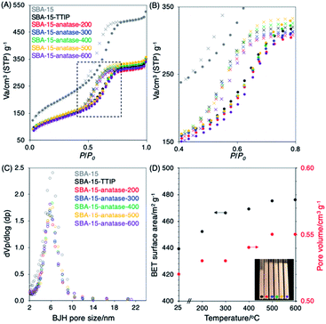
The porosity and the morphology of SBA-15–anatase before and after the crystallization of anatase at the temperature of 200 to 600 °C were followed by N2 adsorption/desorption isotherms and SEM. The N2 adsorption/desorption isotherms were type IV and the BJH pore size was 6 nm for SBA-15 and SBA-15–anatase hybrids (Fig. 1(A), (B) and (C)). The BET surface area and the pore volume of the SBA-15 decreased from 668 to 469 m2 g−1 and from 1.0 to 0.54 cm3 g−1 of SBA-15–TTIP. From the pore volume of the SBA-15 (1 cm3 g−1) and the TTIP content in IPA (TTIP![[thin space (1/6-em)]](https://www.rsc.org/images/entities/char_2009.gif) :
:![[thin space (1/6-em)]](https://www.rsc.org/images/entities/char_2009.gif) IPA = 1
IPA = 1![[thin space (1/6-em)]](https://www.rsc.org/images/entities/char_2009.gif) :
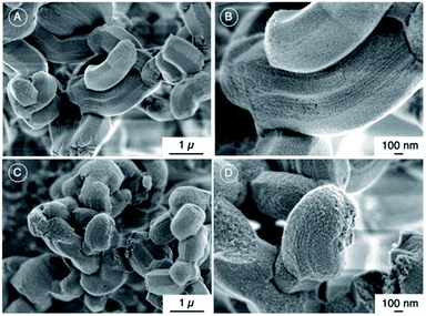
:![[thin space (1/6-em)]](https://www.rsc.org/images/entities/char_2009.gif) 8), the volume of TTIP filled the pores was derived to be 0.11 cm3 g−1. The amount of TiO2 was derived from the volume of the infiltrated TTIP and the density of anatase (3.78 g cm−3) to be ca. 0.4 g, which was converted to 30 wt% of TiO2. The value was consistent with the TiO2 content of the sample derived from XRF. The result suggested the formation of anatase particles from the infiltrated TTIP in the mesopores. The BET surface areas and the pore volumes were slightly higher for the samples heated at the higher temperature (Fig. 1(D)). Bulk density of the SBA-15–TTIP, derived from the volume of the sample (10 mg) in the capillary tube (diameter of 0.018 cm), after heating decreased from 0.15 to 0.11 g1 cm−3 for SBA-15–anatase-200 probably due to the evaporation of IPA, and the bulk density of the SBA-15–anatase did not change upon heating at 200 to 600 °C (Fig. 1(D), the inset). As the shrinkage of the immobilized TiO2 from non-crystalline phase to anatase, the porosity increased. From the pore volume of the SBA-15 (1 cm3 g−1) and the density of anatase (3.78 g cm−3), the amount of the anatase required to fill the pores was calculated to be 3.78 g, which was converted to 79 wt% of TiO2. The pore filling was calculated from the TiO2 content of the hybrids (25 wt%) to be 32% of pore volume. The value was consistent with the decrease of pore volume (30% of pore volume), derived from the pore volume of SBA-15 (1.0 cm3 g−1 of silica) and SBA-15–anatase-600 (0.7 cm3 g−1 of silica), which suggested the formation of the anatase in the mesopores.23 As shown in the SEM images (Fig. 2), no change in the particle morphology of the SBA-15 was seen after the immobilization of TiO2 and the heat treatment at 600 °C and no anatase particles were observed in the external surface of the SBA-15–anatase particles.
8), the volume of TTIP filled the pores was derived to be 0.11 cm3 g−1. The amount of TiO2 was derived from the volume of the infiltrated TTIP and the density of anatase (3.78 g cm−3) to be ca. 0.4 g, which was converted to 30 wt% of TiO2. The value was consistent with the TiO2 content of the sample derived from XRF. The result suggested the formation of anatase particles from the infiltrated TTIP in the mesopores. The BET surface areas and the pore volumes were slightly higher for the samples heated at the higher temperature (Fig. 1(D)). Bulk density of the SBA-15–TTIP, derived from the volume of the sample (10 mg) in the capillary tube (diameter of 0.018 cm), after heating decreased from 0.15 to 0.11 g1 cm−3 for SBA-15–anatase-200 probably due to the evaporation of IPA, and the bulk density of the SBA-15–anatase did not change upon heating at 200 to 600 °C (Fig. 1(D), the inset). As the shrinkage of the immobilized TiO2 from non-crystalline phase to anatase, the porosity increased. From the pore volume of the SBA-15 (1 cm3 g−1) and the density of anatase (3.78 g cm−3), the amount of the anatase required to fill the pores was calculated to be 3.78 g, which was converted to 79 wt% of TiO2. The pore filling was calculated from the TiO2 content of the hybrids (25 wt%) to be 32% of pore volume. The value was consistent with the decrease of pore volume (30% of pore volume), derived from the pore volume of SBA-15 (1.0 cm3 g−1 of silica) and SBA-15–anatase-600 (0.7 cm3 g−1 of silica), which suggested the formation of the anatase in the mesopores.23 As shown in the SEM images (Fig. 2), no change in the particle morphology of the SBA-15 was seen after the immobilization of TiO2 and the heat treatment at 600 °C and no anatase particles were observed in the external surface of the SBA-15–anatase particles.
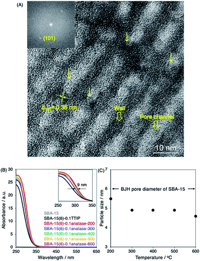
Spherical particles with the diameter of ca. 5 nm were observed in the pore channels of the SBA-15 (Fig. 3(A)). The particles were isolated from each other, which was probably due to the interaction between the surfaces of anatase particles and silica from the dehydroxylation of Ti–OH and Si–OH during the heat treatment. The d(101) value of 0.35 nm of anatase was seen in the TEM image. The result confirmed the crystallization of the anatase nanoparticles in the pore channels of the SBA-15. No absorption was observed for the SBA-15 and the absorption of TiO2 was observed at the wavelength of 300–320 nm for SBA-15–TTIP (Fig. 3(B)). The result suggested that SBA-15 does not absorb UV light. The absorption edge of the SBA-15–TTIP shifted from 320 nm to 330 nm after the heat treatment suggested the crystallization of the non-crystalline TiO2 to anatase. The size and the size distribution of the anatases particle are discussed using UV-vis absorption spectra.27 The sharpness, defined as the width between the maximum and the edge of the UV-vis absorption spectra, presented the size distribution of the anatase particles. The absorption edge of SBA-15–anatase shifted to the shorter wavelength region and the size of the anatase particle, derived from the shift of the band gap energy from a bulk anatase particle (3.2 eV),27 decreased slightly for the samples heated at the higher temperatures (Fig. 3(B) and (C)). The result is consistent with the increasing porosity of the SBA-15–anatase after the crystallization at the higher temperature (Fig. 1(D)). The size (5 nm) of the anatase nanoparticles derived from TEM image and UV-vis absorption spectra and the consistent between the decrease of the pore volume of SBA-15 and the TiO2 content together with the SEM observation that no observation of anatase particles in SEM image confirmed the formation of the anatase nanoparticles in the mesopores (6 nm) of the SBA-15.
The size, the band gap energy and the sharpness of the reported anatase particles prepared in SBA-15![[thin space (1/6-em)]](https://www.rsc.org/images/entities/char_2009.gif) 13–20,28–37 as well as their photocatalytic reactions are summarized in Table S1.† The sharpness for SBA-15–anatase hybrids were relatively narrow compared with the values derived from the reported UV-vis absorption spectra of the anatase particles prepared in SBA-15, confirmed the narrow particle distribution of the anatase particles. The size of the reported anatase particles, derived from the shift of the band gap, prepared in SBA-15, was larger than the pore diameter of the pristine SBA-15, even the crystallization of anatase had been done at the temperature bellow 600 °C (Table S1†).13,17–20,24,33–37 In this study, the size of the anatase particles was within the BJH pore diameter of the SBA-15 (6 nm) keeping narrow particle size distribution even after the crystallization from 200 to 600 °C (Fig. 3(B)).
13–20,28–37 as well as their photocatalytic reactions are summarized in Table S1.† The sharpness for SBA-15–anatase hybrids were relatively narrow compared with the values derived from the reported UV-vis absorption spectra of the anatase particles prepared in SBA-15, confirmed the narrow particle distribution of the anatase particles. The size of the reported anatase particles, derived from the shift of the band gap, prepared in SBA-15, was larger than the pore diameter of the pristine SBA-15, even the crystallization of anatase had been done at the temperature bellow 600 °C (Table S1†).13,17–20,24,33–37 In this study, the size of the anatase particles was within the BJH pore diameter of the SBA-15 (6 nm) keeping narrow particle size distribution even after the crystallization from 200 to 600 °C (Fig. 3(B)).
The optimization of the crystallization temperature for anatase in SBA-15![[thin space (1/6-em)]](https://www.rsc.org/images/entities/char_2009.gif) 18–21 and other porous supports such as zeolites38–40 and clays41–46 had been reported for the uses as photocatalysts. The correlation of the particle sizes of the anatase and the BET surface areas of the hybrids with the crystallization temperatures is shown in Fig. 4 and the reported values of the size of the anatase particles and the porosity of the hybrids at the optimized heat treatment temperatures are summarized in Table S2.† The BET surfaces and the pore volumes of the SBA-15–TiO2 hybrids decreased and the sizes of the anatase particles increased when increased the crystallization temperature from 300 to 600 °C (Fig. 4 and Table S2†).18,20 The collapse of SBA-15–TiO2 hybrid by the heat treatment at 600 °C suppressed the photocatalytic activity of the hybrid for the decompositions of organic compounds (phenol, MB, methyl orange and rhodamine B).20 The size of the anatase particle immobilized on zeolites38,40 and clays44,45 were also increased and the porosities of the hybrids were changed by increasing the crystallization temperature (Fig. 4 and Table S2†).
18–21 and other porous supports such as zeolites38–40 and clays41–46 had been reported for the uses as photocatalysts. The correlation of the particle sizes of the anatase and the BET surface areas of the hybrids with the crystallization temperatures is shown in Fig. 4 and the reported values of the size of the anatase particles and the porosity of the hybrids at the optimized heat treatment temperatures are summarized in Table S2.† The BET surfaces and the pore volumes of the SBA-15–TiO2 hybrids decreased and the sizes of the anatase particles increased when increased the crystallization temperature from 300 to 600 °C (Fig. 4 and Table S2†).18,20 The collapse of SBA-15–TiO2 hybrid by the heat treatment at 600 °C suppressed the photocatalytic activity of the hybrid for the decompositions of organic compounds (phenol, MB, methyl orange and rhodamine B).20 The size of the anatase particle immobilized on zeolites38,40 and clays44,45 were also increased and the porosities of the hybrids were changed by increasing the crystallization temperature (Fig. 4 and Table S2†).
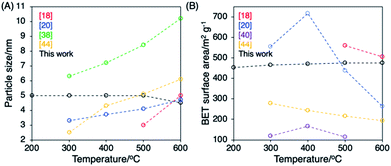 | ||
| Fig. 4 (A) The correlation between the particle sizes of the anatase/BET surface areas of SBA-15–TiO2 hybrids, zeolite–TiO2 hybrids and clay–TiO2 hybrids and the heat treatment temperatures. | ||
In the present study, thanks the well-defined porous structure of a mesoporous silica, the exclusive immobilization as well as the regular special distribution/isolation of the anatase particles in the mesopore,23,24 the size of the anatase particles was maintained keeping the narrow particle size distribution and the porosity of the hybrid was also kept for the crystallization of anatase from 200 to 600 °C. The crystallization of the anatase in the pores of mesoporous silicas with varied compositions and mesostructures are worth investigating to understand the role of the embedded TiO2 on the stability of the mesostructure and the role of mesoporous silica on the crystallization and phase transformation of the embedded TiO2.
3.2 Photocatalytic activity of SBA-15–anatase hybrids
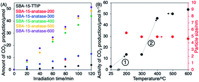
The photocatalytic decomposition of acetic acid of SBA-15–anatase is summarized in Fig. 5, and the crystallization of the anatase in the hybrids was followed by XRD and Raman as shown in Fig. 6. SBA-15–TTIP was active for the photodecomposition of acetic acid, while the reaction efficiency was low (3 μmol h−1 of CO2 production). The improvements of the reaction efficiency upon heating the samples were observed in 2 steps (Fig. 5(B)). The reaction efficiency of SBA-15–TTIP increased 5 times when heated the sample at 200 °C (14 μmol h−1 of CO2 production for SBA-15–anatase-200). A part of the immobilized TiO2 was thought to be crystallized to anatase. However, the amount of the anatase is too small to be detected by XRD and Raman (Fig. 6). Raman signal ascribable to anatase was observed for SBA-15–anatase-300 (Fig. 6(B)), while the diffraction due to anatase was not observed in the XRD pattern (Fig. 5(A)), due to the higher sensitivity of Raman to detect anatase crystal compared with XRD.47 However, no improvement in the reaction efficiency was seen when the crystallization temperature was 300 °C. Non-crystalline TiO2, which is thought to be less active as photocatalyst, remained in the SBA-15–anatase even after the heat treatment at 300 °C.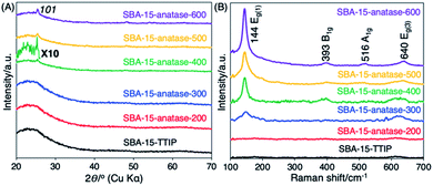 | ||
| Fig. 6 (A) X-ray powder diffraction patterns and (B) Raman spectra of SBA-15–TTIP, SBA-15–anatase-200, SBA-15–anatase-300, SBA-15–anatase-400, SBA-15–anatase-500 and SBA-15–anatase-600. | ||
The reaction efficiency of SBA-15–anatase-400 (45 μmol h−1 of CO2 production) was higher than SBA-15–anatase-300 for 4 times. The 101 diffraction peak of anatase was clearly observed in the XRD patterns of SBA-15–anatase-400, SBA-15–anatase-500 and SBA-15–anatase-600 (Fig. 5(A)). The intensity of the Raman signals increased with the higher crystallization temperature of anatase, suggesting that the anatase content increased (Fig. 5(B)). No substantial improvement of the reaction efficiency was observed when the hybrid was heated at 500 and 600 °C. The weak intensity of the diffraction peaks may be probably due to the scattering contrast between the anatase particles and the pore wall. The isolation of the anatase nanoparticles from SBA-15 and the characterization of the isolated particles are being done in our laboratory and the results will be reported separately.
The possible mechanism of the photodecomposition of acetic acid by TiO2 particles has been proposed as the direct oxidation of the acetic acid by the photogenerated hole (h+)48 or the oxidation of the acetic by the superoxide anion radical from the reaction of the molecular oxygen and the photogenerated electron.49 Another possible mechanism is production of peroxy radical, as a carrier for a radical chain reaction (RCR), through reaction with radical species generated by the oxidation of acetic acid and h+.50 It is difficult to clarify that the acetic acid was decomposed through which mechanism, because the intermediates (·CH3, ·CH2COOH, ·OH, HOO˙, O2˙−) are not stable and can be further reacted without the light irradiation. For the photodecomposition of acetic acid by SBA-15–anatase, the acetic acid molecule was diffused into the mesopores and had the reaction with the anatase nanoparticles located in the mesopores. The slow diffusion of the acetic acid (the molecular size of 0.5 nm) through the space (1 nm) between the anatase nanoparticles (5 nm) and the pore walls in the pore channel (6 nm) may have induced the direct reduction of the acetic acid by the h+ on the surface of the anatase nanoparticles.
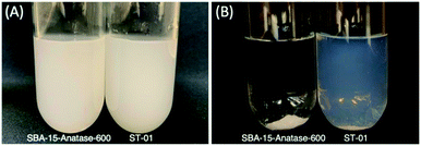
The photocatalytic activity of the SBA-15–anatase was compared with the commercial TiO2 nanoparticles, which have been used for the photocatalytic decomposition of acetic acid under the same conditions of this study.51 The photocatalytic activities together with the sizes of the anatase nanoparticles are summarized in Table 1, where the reaction efficiency of the SBA-15–anatase heated over 400 °C (45–55 μmol h−1 of CO2 production) was high compared with the commercial anatase particles (10–53 μmol h−1 of CO2 production). The high crystallinity as well as the isolation of the anatase nanoparticles in the mesopores suppressed the charge recombination resulted the high reaction efficiency. The light harvesting to the anatase nanoparticles is thought to be enhanced by the multiple light reflections in the pore channels.52 The light scattering may be difficult to be avoided due to the surface roughness of the SBA-15 particles seen in the SEM image (Fig. 2(B)). Irrespective of the negative aspects, the hybrid was photocatalytically active comparable to P25, suggesting the high potential of the formed anatase particles and positive roles of the pores to concentrate substrates from the solution. In addition, the SBA-15–anatase samples was easily collected from the suspension by centrifugation as shown in Fig. 7(B) (SBA-15–anatase-600 was used), compared with the anatase nanoparticle (ST-01), which still remained in the supernatant.
| Sample | Crystallite sizef/nm | Activity/μmol h−1 of CO2 production |
|---|---|---|
| a Commercial TiO2 nanoparticles were obtained from Catalysis Society of Japan.b Commercial TiO2 nanoparticles were obtained from Nippon Aerosil.c Commercial TiO2 nanoparticles were obtained from Tayca.d Commercial TiO2 nanoparticles were obtained from Hombikat.e Commercial TiO2 nanoparticles were obtained from Ishihara Sangyo.f The crystallite size of the anatase particle derived from the 101 diffraction of anatase from XRD pattern using Scherrer equation.g The crystallite size of the anatase particles was derived from the shift of the band gab energy from band gap energy of a bulk anatase particle (3.2 eV). | ||
| TIO-7a | 8 | 31 |
| TIO-8a | 4 | 20 |
| TIO-9a | 10 | 28 |
| TIO-12a | 6 | 28 |
| VP-P90b | 5 | 43 |
| PC-101c | 8 | 13 |
| Hombikatd | 9 | 33 |
| ST-01e | 8 | 30 |
| P25b | 21 | 53 |
| SBA-15–anatase-200 | No peak (5.6)g | 14 |
| SBA-15–anatase-300 | No peak (4.9)g | 14 |
| SBA-15–anatase-400 | Too broad (4.9)g | 45 |
| SBA-15–anatase-500 | Too broad (4.9)g | 50 |
| SBA-15–anatase-600 | Too broad (4.3)g | 55 |
4 Conclusions
The photocatalytic activity of the well-defined anatase particle (5 nm) prepared in mesoporous silica, SBA-15 with the pore size of 6 nm was examined by using the photocatalytic decomposition of acetic acid as a model reaction. The crystallization of the anatase particle in the mesoporous silica was examined by heating from 200 to 600 °C, where the mesoporous structure of the mesoporous titania–silica hybrids was retained and the size of the anatase particle (5 nm) was within the BJH pore diameter (6 nm) of the mesoporous silica. The photocatalytic activity of the titania–silica hybrid heated lower than 300 °C was low (3–14 μmol h−1 of carbon-dioxide production), while the titania–silica hybrid heated over 400 °C gave the high reaction efficiency (45–55 μmol h−1 of carbon-dioxide production), where the reaction efficiency better than the commercial titania nanoparticles (10–53 μmol h−1 of carbon-dioxide production). Further study on the photocatalytic activities of the titania–silica hybrid as well as the anatase particles isolated from the template are being done in our laboratory.Conflicts of interest
There are no conflicts to declare.Acknowledgements
This work was supported by the Research Chair Grant 2017 (grant number FDA-CO-2560-5655) from the National Science and Technology Development Agency (NSTDA), Thailand, and the Cooperative Research Program of Institute for Catalysis, Hokkaido University. One of the authors (K. G. V.) acknowledges Vidyasirimedhi Institute of Science and Technology (VISTEC) for the scholarship to his PhD study.Notes and references
- R. J. White, R. Luque, V. L. Budarin, J. H. Clark and D. J. Macquarrie, Chem. Soc. Rev., 2009, 38, 481 RSC.
- K. Ariga, A. Vinu, Y. Yamauchi, Q. Ji and J. P. Hill, Bull. Chem. Soc. Jpn., 2011, 25, 1 Search PubMed.
- M. Ogawa, J. Photochem. Photobiol., C, 2002, 3, 129 CrossRef CAS.
- X. Qian, K. Fuku, Y. Kuwahara, T. Kamegawa, K. Mori and H. Yamashita, ChemSusChem, 2014, 7, 1528 CrossRef CAS PubMed.
- Y. Kuwahara and H. Yamashita, J. Mater. Chem., 2011, 21, 2407 RSC.
- K. Mori, H. Yamashita and M. Anpo, RSC Adv., 2012, 2, 3165 RSC.
- K. G. Vibulyaseak, S. B. Deepracha and M. Ogawa, J. Solid State Chem., 2019, 270, 162 CrossRef CAS.
- X. Wang, W. Lian, X. Fu, J. M. Basset and F. Lefebvre, J. Catal., 2006, 238, 13 CrossRef CAS.
- S. Zheng, L. Gao, Q. H. Zhang and J. K. Guo, J. Mater. Chem., 2000, 10, 723 RSC.
- J. Strunk, W. C. Vining and A. T. Bell, J. Phys. Chem. C, 2010, 114, 16937 CrossRef CAS.
- M. Bandyopadhyay, A. Birkner, M. W. E. Van den Berg, K. V. Klementiev, W. Schmidt, W. Grünert and H. Gies, Chem. Mater., 2005, 17, 3820 CrossRef CAS.
- R. Singh, R. Bapat, L. Qin, H. Feng and V. Polshettiwar, ACS Catal., 2016, 6, 2770 CrossRef CAS.
- C. Jiang, K. Y. Lee, C. M. Parlett, M. K. Bayazit, C. C. Lau, Q. Ruan, S. J. Moniz, A. F. Lee and J. Tang, Appl. Catal., A, 2016, 521, 133 CrossRef CAS.
- R. van Grieken, J. Aguado, M. J. López-Muñoz and J. Marugán, J. Photochem. Photobiol., A, 2002, 148, 315 CrossRef CAS.
- C. L. Peza-Ledesma, L. Escamilla-Perea, R. Nava, B. Pawelec and J. L. G. Fierro, Appl. Catal., A, 2010, 375, 37 CrossRef CAS.
- T. Shindo, N. Koizumi, K. Hatakeyama and T. Ikeuchi, Int. J. Soc. Mater. Eng. Resour., 2011, 18, 11 CrossRef CAS.
- M. Besançon, L. Michelin, L. Josien, L. Vidal, K. Assaker, M. Bonne, B. Lebeau and J. L. Blin, New J. Chem., 2016, 40, 4386 RSC.
- J. Yang, J. Zhang, L. Zhu, S. Chen, Y. Zhang, Y. Tang, Y. Zhu and Y. Li, J. Hazard. Mater., 2006, 137, 952 CrossRef CAS PubMed.
- D. R. Sahu, L. Y. Hong, S. C. Wang and J. L. Huang, Microporous Mesoporous Mater., 2009, 117, 640 CrossRef CAS.
- C. Liu, X. Lin, Y. Li, P. Xu, M. Li and F. Chen, Mater. Res. Bull., 2016, 75, 25 CrossRef CAS.
- M. Bonne, S. Pronier, Y. Batonneau, F. Can, X. Courtois, S. Royer, P. Marécot and D. Duprez, J. Mater. Chem., 2010, 20, 9205 RSC.
- D. Zhao, Q. Huo, J. Feng, B. F. Chmelka and G. D. Stucky, J. Am. Chem. Soc., 1998, 120, 6024 CrossRef CAS.
- K. Vibulyaseak, S. Bureekaew and M. Ogawa, Langmuir, 2017, 33, 13598 CrossRef CAS PubMed.
- K. Vibulyaseak, W. A. Chiou and M. Ogawa, Chem. Commun., 2019, 55, 8442 RSC.
- S. Brunauer, P. H. Emmett and E. Teller, J. Am. Chem. Soc., 1938, 60, 309 CrossRef CAS.
- E. P. Barrett, L. G. Joyner and P. P. Halenda, J. Am. Chem. Soc., 1951, 73, 373 CrossRef CAS.
- L. Brus, J. Phys. Chem., 1986, 90, 2555 CrossRef CAS.
- W. Wang and M. Song, Mater. Res. Bull., 2006, 41, 436 CrossRef CAS.
- H. Lachheb, O. Ahmed, A. Houas and J. P. Nogier, J. Photochem. Photobiol., A, 2011, 226, 1 CrossRef CAS.
- Z. Wang, F. Zhang, Y. Yang, B. Xue, J. Cui and N. Guan, Chem. Mater., 2007, 19, 3286 CrossRef CAS.
- S. Zhu, D. Zhang, X. Zhang, L. Zhang, X. Ma, Y. Zhang and M. Cai, Microporous Mesoporous Mater., 2009, 126, 20 CrossRef CAS.
- A. M. Busuioc, V. Meynen, E. Beyers, M. Mertens, P. Cool, N. Bilba and E. F. Vansant, Appl. Catal., A, 2006, 312, 153 CrossRef CAS.
- Y. Li, N. Li, J. Tu, X. Li, B. Wang, Y. Chi, D. Liu and D. Yang, Mater. Res. Bull., 2011, 46, 2317 CrossRef CAS.
- F. Zhang, X. Carrier, J. M. Krafft, Y. Yoshimura and J. Blanchard, New J. Chem., 2010, 34, 508 RSC.
- L. Zhao and J. Yu, J. Colloid Interface Sci., 2006, 304, 84 CrossRef CAS PubMed.
- A. Mehta, A. Mishra, M. Sharma, S. Singh and S. Basu, J. Nanopart. Res., 2016, 18, 209 CrossRef.
- C. Salameh, J. P. Nogier, F. Launay and M. Boutros, Catal. Today, 2015, 257, 35 CrossRef CAS.
- S. Ko, P. D. Fleming, M. Joyce and P. Ari-Gur, Mater. Sci. Eng., C, 2009, 164, 135 CrossRef CAS.
- D. Kanakaraju, J. Kockler, C. A. Motti, B. D. Glass and M. Oelgemöller, Appl. Catal., B, 2015, 166, 45 CrossRef.
- N. Amini, M. Soleimani and N. Mirghaffari, Environ. Sci. Pollut. Res., 2019, 26, 16877 CrossRef CAS PubMed.
- J. Sterte, Clays Clay Miner., 1986, 34, 658 CrossRef CAS.
- S. Yamanaka, T. Nishihara, M. Hattori and Y. Suzuki, Mater. Chem. Phys., 1987, 17, 87 CrossRef CAS.
- Y. Kameshima, Y. Tamura, A. Nakajima and K. Okada, Appl. Clay Sci., 2009, 45, 20 CrossRef CAS.
- D. Chen, Q. Zhu, F. Zhou, X. Deng and F. Li, J. Hazard. Mater., 2012, 235, 186 CrossRef PubMed.
- K. M. Kutláková, J. Tokarský, P. Kovář, S. Vojtěšková, A. Kovářová, B. Smetana, J. Kukutschová, P. Čapková and V. Matějka, J. Hazard. Mater., 2011, 188, 212 CrossRef PubMed.
- M. N. Chong, V. Vimonses, S. Lei, B. Jin, C. Chow and C. Saint, Microporous Mesoporous Mater., 2009, 117, 233 CrossRef CAS.
- R. Zukerman, L. Vradman, L. Titelman, L. Zeiri, N. Perkas, A. Gedanken, M. V. Landau and M. Herskowitz, Mater. Chem. Phys., 2010, 122, 53 CrossRef CAS.
- Y. Nosaka, K. Koenuma, K. Ushida and A. Kira, Langmuir, 1996, 12, 736 CrossRef CAS.
- B. Ohtani, Y. Nohara and R. Abe, Electrochemistry, 2008, 76, 147 CrossRef CAS.
- A. Heller, Acc. Chem. Res., 1995, 28, 503 CrossRef CAS.
- B. Ohtani, O. O. P. Mahaney, F. Amano, N. Murakami and R. Abe, J. Adv. Oxid. Technol., 2010, 13, 247 CAS.
- Z. Jiang, Z. Huang, W. Guo and W. Shangguan, J. Catal., 2019, 370, 210 CrossRef CAS.
Footnote |
| † Electronic supplementary information (ESI) available. See DOI: 10.1039/d0ra04528d |
| This journal is © The Royal Society of Chemistry 2020 |


