 Open Access Article
High-sensitivity, fast-response flexible pressure sensor for electronic skin using direct writing printing
Xiaojun Chen a,
Xitong Lina,
Deyun Moa,
Xiaoqun Xiaa,
Manfeng Gonga,
Haishan Lian*a and
Yihui Luo*b
aSchool of Mechanical and Electronic Engineering, Lingnan Normal University, Zhanjiang 524048, China. E-mail: lianhs@lingnan.edu.cn
bDepartment of Mechanical & Electrical Engineering, Xiamen University, 361102, China. E-mail: 19920161151457@stu.xmu.edu.cn
First published on 13th July 2020
Abstract
Bionic electronic skin with human sensory capabilities has attracted extensive research interest, which has been applied in the fields of medical health diagnosis, wearable electronics, human–computer interaction, and bionic prosthetics. Electronic skin tactile pressure sensing required high sensitivity, good resolution and fast response for sensing different pressure stimuli. In particular, there were still great challenges in the detection of wide pressure and the preparation of sensitive unit microstructures. Here, the direct-write printing of Weissenberg principle to fabricate GNPs/MWCNT filled conductive composite flexible pressure sensors on PDMS substrates was proposed. The effects of platform moving speed, microneedle rotation speed and the number of direct-write times on the line width of the pressure sensitive structure were investigated based on orthogonal experiments, and the optimal direct-write printing parameters were obtained. The performance of the S-shaped polyline pressure sensor was tested, in which the sensitivity could reached 0.164 kPa−1, and the response/recovery time was 100 ms and 100 ms respectively. The capture cases of objects of different quality and objects with flat/curved surfaces were successively demonstrated to exhibit its excellent sensitivity, stability and fast response performance. This work may paved the road for future integration of high-performance electronic skin in smart robotics and prosthetic solutions.
1 Introduction
Flexible and stretchable electronics have great potential application prospects in the fields of energy production,1 biomedicine,2,3 bionic robots,4,5 wearable electronics.6–8 In particular, artificial electronic skin simulates the basic characteristics of human skin (such as pressure perception, stretchability and transparency), which has attracted extensive research interest.9 In order to exhibit the unique properties of human skin, electronic skin must cover dynamic and irregular surfaces and withstand a variety of repeated and prolonged mechanical stimuli, such as pressure, strain, and flexion. Additionally, as a multifunctional sensor, it must satisfy the requirements of high stretchability, high sensitivity, wide sensing range, and fast responsivity.Previous research is devoted to using different new sensitive materials and various optimized structures to build flexible pressure sensors with similar pressure sensing functions for human skin. Until now, various flexible and stretchable physical sensors that measure and quantify electrical signals generated from human activity have been achieved based on different sensing mechanisms, in particular piezoelectricity, capacitance, and piezoresistivity10 (as shown in Table 1). According to the pressure sensing characteristics of biological skin, pressure sensing is mainly includes into low pressure induction (0–10 kPa), which can be used for human body vocalization, pulse, micro touch; medium pressure induction (10–100 kPa), which is held in hand pressure range can be used for health monitoring, plantar pressure distribution, catching.11 In order to get closer to the sensitive characteristics of biological skin, most research literature mainly improves the sensitive characteristics and response speed of flexible pressure sensors from the aspects of sensing materials and sensing mechanisms. Wang et al. developed an electronic skin flexible pressure sensor using a high-concentration silver nanowire-polyurethane elastic composite material. The sensitivity in the low-pressure region of <30 Pa and 30–70 Pa was 5.54 kPa−1 and 0.88 kPa−1, respectively.12 Lou et al. developed an electronic skin flexible tactile sensor based on graphene materials, which could quickly sense small pressure changes. The minimum detectable pressure, sensitivity and response time were 1.2 Pa, 15.6 kPa−1 and 5 ms, respectively. It showed the application potential in pulse and voice recognition.13
| Transduction principles | Material/structure | Range | Sensitivity | Response time | Ref. |
|---|---|---|---|---|---|
| Capacitance | Fluorosilicone/air gap | 0.5–190 kPa | 0.91 kPa−1 | <1 s | Bao et al.19 |
| PDMS microhairy | 0.4–5 kPa | 0.58 kPa−1 | 0.03 s | Pang et al.27 | |
| Piezoresistivity | CNT/PDMS porous | 0.25–100 kPa | 0.2 kPa−1 | 1.3 Hz | Peng et al.28 |
| Gold NWs | 13 Pa to 50 kPa | 1.14 kPa−1 | Not known | Guo et al.29 | |
| Piezoelectricity | ZnO nanowire | 0–30 kPa | 0.37 kPa−1 | 0.15 s | Peng et al.30 |
In addition, surface microstructures provide opportunities for improving the performance of flexible pressure sensors using micromachining technology. Previous literatures have proved that microstructures such as elastic micro-pyramid arrays,14 dome-shaped structures15 and interconnected nanofiber arrays16 are effective approach to obtain high-sensitivity sensing signals. Jang et al. presented the formation of active-matrix pressure-sensitive MoS2 FET arrays for sensing wide tactile pressure ranges. This active-matrix sensor array with the outstanding spatial and temporal resolutions enabled enlarge the detectable range of pressure from 70 Pa to 5 MPa.17 Chen et al. fabricated a resistive flexible pressure sensor with graphene microstructure array, which has a sensitivity of up to 5.5 kPa−1 within <100 Pa, a detection limit of 1.5 Pa and response time of 0.2 ms.18 Bao et al. proposed a high-performance flexible pressure sensor with a microstructured rubber dielectric layer, which enables the sensor to have a maximum sensitivity of 8.4 kPa−1, a response time of <10 ms, and stability of more than 15![[thin space (1/6-em)]](https://www.rsc.org/images/entities/char_2009.gif) 000 cycles.19 Kim et al. developed a wearable flexible pressure sensor with a layered structure using elastic carbon nanotube microwires and its sensitivity was only 0.5 MPa−1 when the pressure was greater than 10 kPa.20 However, the pressure sensor mentioned above has a longer response time (>0.5 s) in the mid-pressure range.21 The pressure detection range and sensing performance are difficult to adapt to medium pressure sensing occasions, which limits the requirements for electronic skin to require wide pressure detection.22,23 Therefore, there is an urgent need to develop a method for manufacturing flexible pressure sensors with adjustable microstructure surfaces, making it suitable for wide pressure range detection and fast response.
000 cycles.19 Kim et al. developed a wearable flexible pressure sensor with a layered structure using elastic carbon nanotube microwires and its sensitivity was only 0.5 MPa−1 when the pressure was greater than 10 kPa.20 However, the pressure sensor mentioned above has a longer response time (>0.5 s) in the mid-pressure range.21 The pressure detection range and sensing performance are difficult to adapt to medium pressure sensing occasions, which limits the requirements for electronic skin to require wide pressure detection.22,23 Therefore, there is an urgent need to develop a method for manufacturing flexible pressure sensors with adjustable microstructure surfaces, making it suitable for wide pressure range detection and fast response.
The methods to fabricate electronic skin flexible pressure sensors mainly include photolithography, chemical vapor deposition (CVD), micro-contact printing, transfer, spray coating, screen printing and direct writing spray printing.24–26 Among these technologies, direct writing inkjet printing is considered to be the most promising method for the manufacture of flexible sensors because of its simple, fast and low-cost advantages, which can realize the flexible manufacturing of complex sensitive structures.
Here, a direct-write printing technology based on the Weissenberg principle is proposed for fabricating sensitive structures of flexible pressure sensors. The GNPs/MWCNT composite material is patterned and deposited on a flexible PDMS substrate as a pressure sensitive unit to realize a wide pressure range detection flexible pressure sensor. We demonstrated the application of flexible pressure sensors to capture objects of different qualities and flat/curved surfaces. The experimental results reveal the advantages of the sensors with high sensitivity and fast response. In the future, it will have huge application prospects in the fields of medical health detection, medical implants and intelligent prostheses.
2 Experiments and methods
2.1 Materials
Graphene nanoplatelets (GNPs, MW = 12.01 g mol−1, form: dispersion in H2O, conc.: 1 mg mL−1) and multi-walled carbon nanotubes (MWCNT, assay: >98% carbon basis) were purchased from Sigma-Aldrich. PEO (average molecular weight: 300![[thin space (1/6-em)]](https://www.rsc.org/images/entities/char_2009.gif) 000 g mol−1) and ethanol were purchased from Xiamen Green Reagent Glass Instrument Co., Ltd. The PEO powder was dissolved in a solvent mixture of deionized water and ethanol (3
000 g mol−1) and ethanol were purchased from Xiamen Green Reagent Glass Instrument Co., Ltd. The PEO powder was dissolved in a solvent mixture of deionized water and ethanol (3![[thin space (1/6-em)]](https://www.rsc.org/images/entities/char_2009.gif) :
:![[thin space (1/6-em)]](https://www.rsc.org/images/entities/char_2009.gif) 1 volume ratio) to obtain a solution concentration of 12%. GNPs/MWCNT (mass ratio 1000
1 volume ratio) to obtain a solution concentration of 12%. GNPs/MWCNT (mass ratio 1000![[thin space (1/6-em)]](https://www.rsc.org/images/entities/char_2009.gif) :
:![[thin space (1/6-em)]](https://www.rsc.org/images/entities/char_2009.gif) 1) and 12% PEO polymer were thoroughly mixed to prepare a precursor solution with a concentration of 6 wt%. These mixed solutions were stirred for 2H at 200 rpm using a magnetic stirrer (IKA C-MAG HS 7, Germany). Then, the mixed solutions were sonicated using the ultrasonic device (KUDOS, Shanghai) in water bath at 80% power and 50 kHz frequency for 3 h to make the mixture uniform and avoid agglomeration. PDMS was purchased from Dow Corning Corporation (Sylgard 184, basic component to curing agent mass ratio 10
1) and 12% PEO polymer were thoroughly mixed to prepare a precursor solution with a concentration of 6 wt%. These mixed solutions were stirred for 2H at 200 rpm using a magnetic stirrer (IKA C-MAG HS 7, Germany). Then, the mixed solutions were sonicated using the ultrasonic device (KUDOS, Shanghai) in water bath at 80% power and 50 kHz frequency for 3 h to make the mixture uniform and avoid agglomeration. PDMS was purchased from Dow Corning Corporation (Sylgard 184, basic component to curing agent mass ratio 10![[thin space (1/6-em)]](https://www.rsc.org/images/entities/char_2009.gif) :
:![[thin space (1/6-em)]](https://www.rsc.org/images/entities/char_2009.gif) 1). HS-8200 Ag (Hanstars) were used as the electrode material. Glass bottles, batteries, and glass plates were purchased from Xiamen Green Reagent Glass Instrument Co., Ltd. Deionized water was obtained from the Pen-Tung Sah Institute of Micro-Nano Science and Technology in Xiamen University.
1). HS-8200 Ag (Hanstars) were used as the electrode material. Glass bottles, batteries, and glass plates were purchased from Xiamen Green Reagent Glass Instrument Co., Ltd. Deionized water was obtained from the Pen-Tung Sah Institute of Micro-Nano Science and Technology in Xiamen University.
2.2 Direct-write printing of pressure-sensitive structures
The pressure-sensitive structure was fabricated using a self-made direct-write printing system. As shown in Fig. 1, it mainly included a direct-write printing module, a high-precision X-Y mobile platform, a substrate-added module, and an industrial CCD camera. The direct-write printing module was composed of micro pipes (inner diameter: 0.25 ± 0.02 mm) and micro needles (0.16 ± 0.01 mm). The X-Y mobile platform had a minimum resolution of 0.001 μm and an accuracy of ± 0.2 μm. The heating module (temperature: 80 °C) was used to cure sensitive structures during direct printing. The industrial camera CCD was used to observe the solution shape at the nozzle and the entire printing process.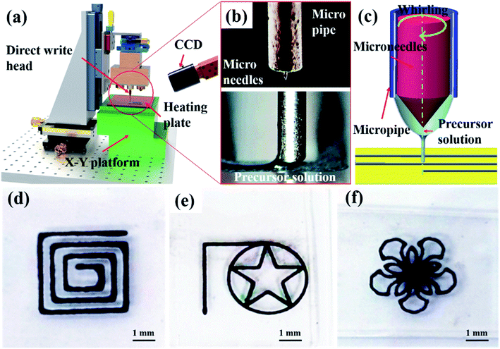 | ||
| Fig. 1 (a) Direct writing printing system; (b) picture of nozzle structure; (c) direct writing printing process; (d–f) various direct writing patterns. | ||
2.3 Characterization
Continuous zoom stereo microscope (SZ66, China) and Auto Optical Microscope (MIT series, China) were used to observe the surface morphology of sensitive structures. The sensitive structure and PDMS microstructure were tested using scanning electron microscope (SEM JSM-IT500a, Japan) and transmission electron microscopy (TEM, JEM-1400, Japan). The electrical characteristics and pressure sensitive characteristics of the pressure sensor were tested by a pressure gauge (Handpi HP-5N, China) and a digital multimeter (Agilent 34410A, United States).3 Results and discussion
3.1 Pattern printing and parameter optimization of sensitive structures
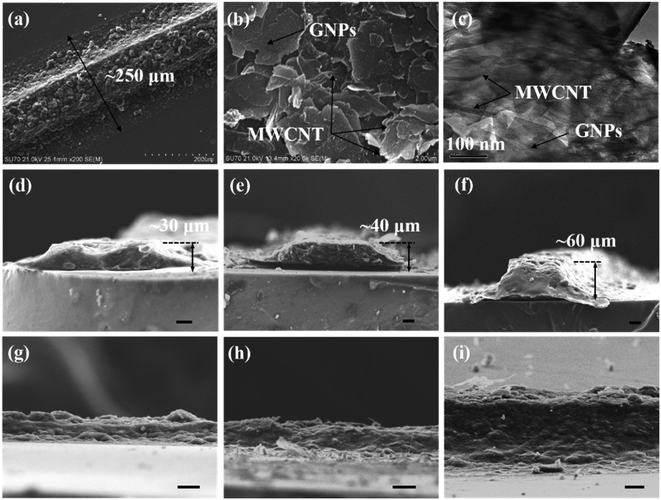
The self-made direct-write platform was used to fabricate the sensitive structure of the sensor, as shown in Fig. 1a. According to the fluid transport characteristics of the Weissenberg effect, the GNPs/MWCNT precursor solution of the micro-pipe was transported to the tip of the micro-needle due to the high-speed rotation of the micro-needle (Fig. 1b). The pattern of sensitive structures was printed on the surface of the substrate via the micro-contact form of the microneedle and the substrate (Fig. 1c). Our group's previous research confirmed that the micro-scale Weissenberg effect has excellent fluid transport characteristics and demonstrated its application in the continuous supply of printing solutions. It has been widely used in the manufacture of micro-nanowires, spiral optical fibers, and nanofibers.31,32 This liquid supply method effectively solved the problems of large flow resistance of high-viscosity fluid and clogging of the nozzle in the traditional printing process.33 Therefore, it could quickly print various patterns such as labyrinth patterns, circular-pentagonal patterns and flower patterns, as shown in Fig. 1d–f. This technology demonstrated the manufacturing capabilities of simple straight-line structures, arc-shaped curve structures, and complex curve structures.3D sensitive structure could be manufactured using layer-by-layer stacking based on the Weissenberg direct writing technology (Fig. 2a). The printed line appeared as a trapezoidal structure with a line width of 250 μm (bottom), and the surface microstructure was relatively rough. Transmission electron microscopy (TEM) and scanning electron microscopy (SEM) were used to characterize the microstructure of the sensitive structure of the sensor, as shown in Fig. 2b and c. TEM and SEM images show that MWCNTs were randomly dispersed in the GNPs solution, forming a bridge. The bridge part provided an effective conductive path for the pressure-sensitive structure and formed a three-dimensional conductive network. MWCNT/GNPs composites had good dispersion in sensitive structures under the Weissenberg direct writing process. The continuous rotation of the microneedles avoided the agglomeration of MWCNT/GNPs. In addition, the conductive network structure provided more transmission channels and enhances the conductive stability.
As shown in Fig. 2d–f, the microstructure features of the sensitive structure were investigated for the number of direct-writes of 20, 40 and 60 times, respectively. When the number of direct writes was 20 times, the sensitive structure exhibited a concave shape in the middle, which could be attributed to the coffee ring effect. However, when the number of direct writing was 40 and 60 times, the middle concave structure was gradually filled with the printed solution, and then the cross-section of the sensitive structure showed a trapezoidal structure.34 As the number of direct writes continues to increased, the height of the trapezoidal structure continues to increased. The printing solution easily slipped off the top, resulting in an increase in the aspect ratio of the trapezoidal structure (the area of the top decreases), which was beneficial to improve the response and stability of the pressure sensor. In addition, the rough surface morphology of the pressure-sensitive structure was conducive to reducing the contact area of the pressure surface, which could further improve the performance of the pressure sensor,35 as shown in Fig. 2g–i.
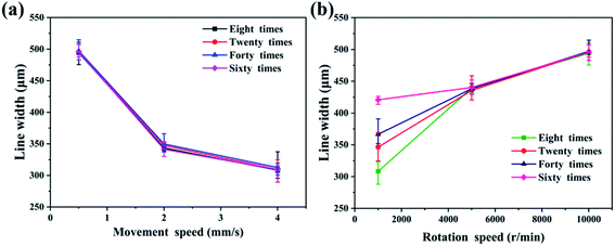
The size of the printed line width (the maximum line width at the bottom of the sensitive unit that can be observed.) determined the size of the sensitive structure during the direct printing process. Multi-parameter control was adopted to obtain a sensitive structure with suitable line width. The effects of platform moving speed, microneedle rotation speed and the number of direct-write times on the line width of the pressure sensitive unit were investigated based on orthogonal experiments, and the optimal direct-write printing parameters were obtained.
When the moving speed increased from 0.5 mm s−1, 2 mm s−1 to 4 mm s−1, the average line width decreased from 500 μm, 340 μm to 300 μm, respectively (Fig. 3a). The print line width decreases as the moving speed increased. The number of direct writes had little effect on the average line width. When the number of direct writes was 8, 20, and 40 to 60 times, the average line width remains almost unchanged, which was mainly due to the stability of the jet. Theoretically, the increase in the rotation speed of the microneedle caused the elastic recovery force of the solution to increase, resulting in an increase in the amount of liquid supplied. As shown in Fig. 3b, the average line width increased from 320 μm to 460 μm. Therefore, in order to obtain a suitable line width of the sensitive structure, the parameters of the platform moving speed and the microneedle speed needed to be compromised.
The deformation of the sensitive structure was the main source of pressure-sensitive characteristics. The ability of substrate deformation was a key factor in determining sensor performance. The deformability of the substrate could be obtained by increasing the thickness of the substrate and the microstructure of the substrate surface, where the microstructure of the substrate surface will increase the difficulty of direct write printing. Therefore, in order to improve the performance of the sensor, we investigated the relationship between the substrate thickness and the strain of the sensitive element using finite element simulation software. The finite element model of the pressure sensor was constructed, including the pressurized block, the encapsulation layer, the sensitive unit and the substrate, as shown in Fig. 4a. When a pressure of 30 kPa was applied to the pressing block, the strain distribution of the sensitive element of different substrates was obtained, as shown in Fig. 4b–f. Obviously, there was maximum deformation at the pressure edge. As the substrate thickness increased from 300 μm to 4 mm, the maximum strain of the sensitive structure increased from 0.006 to 0.025. Considering the performance and portability of the sensor, an excellent strain capability could be obtained with a substrate thickness of 500 μm.
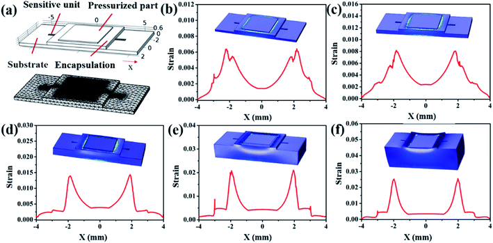 | ||
| Fig. 4 (a) Simulation model of flexible pressure sensor; (b)–(f) relationship between substrate thickness (300 μm, 500 μm, 1 mm, 2 mm, 4 mm) and strain. | ||
3.2 Performance of flexible pressure sensor
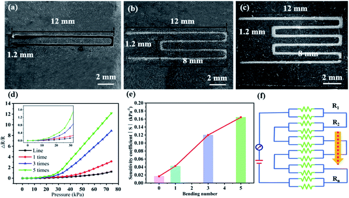
According to previous literature, the accumulative effect of the polyline could improve the pressure-sensitive performance of the sensor and the sensing area of the sensitive structure. The pressure-sensitive characteristics of sensitive structures with different folding patterns were investigated, as shown in Fig. 5a–c. The relationship between resistance and pressure was evaluated using a pressure-impedance test system. The change resistance and sensitivity coefficient could be calculated according to formulas (1) and (2).| ΔR = Ra − R | (1) |
 | (2) |
The curves of pressure-sensitive characteristics (ΔR/R-pressure) and sensitivity were shown in Fig. 5d and e. When the applied pressure increased from 0 kPa to 75 kPa, the ΔR/R of different patterns increased with the pressure, showing a positive piezoresistive effect. As shown in the sensitive structure pattern in Fig. 5c, its ΔR/R increased from 0 to 12.17, and the positive piezoresistive effect increased with the number of bending regions. Its sensitivity had increased from 0.017 kPa−1 to 0.164 kPa−1. This multi-broken line sensitive structure was similar to the series result of multiple resistors, as shown in Fig. 5f. Generally, the more the bending number of the sensitive structure increased, the larger the area it senses. According to the finite element simulation results, the deformation of the pressure edge of the sensitive structure was the most obvious, resulting in the rapid increase of the resistance of the edge bending line. Therefore, its positive piezoresistive effect was enhanced by the cumulative effect based on the series resistance. However, the increase in the bending number of the sensitive structure will inevitably lead to an increase in the sensor area, which was not conducive to integrated manufacturing. According to the detection range and application requirements of the sensor, we needed to select a moderate bending number of the sensitive unit to obtain a good detection effect.
In order to reveal the sensitive mechanism of the pressure sensor, a sandwich pressure sensor working model was established, as shown in Fig. 6. In the absence of pressure, the sensitive structure remained in a laminated shape, and the conductive network composed of GNPs/MWCNT has good conductivity and no resistance change (Fig. 6a). As the applied pressure increases, the pressure in the tip region of the microstructure of the encapsulation layer increased, resulting in an increase in the deformation of the micro-nano structure of the sensor (Fig. 6b and c). The encapsulation layer structure is one of the factors to improve the sensitivity of the sensor. The area of deformation of the sensitive structure of the sensor increases due to the introduction of the microstructure of the encapsulation layer. This microstructure can cause greater strain on the sensitive unit, thereby enhancing the sensitivity of the sensitive unit. The 3D conductive network composed of GNPs/MWCNT was damaged by recoverability due to deformation, resulting in the resistance value continuously increasing with increasing pressure.36 Each conductive network could be considered as a variable resistor (Rn), and its resistance value depended on the contact of the conductive network (Fig. 5f). The application of external pressure that causes deformation of the sensitive structure causes the Rn between the GNPs/MWCNT network to decrease, which was the reason for the increased resistance. When the pressure was released, the conductive network returns to its original state, and the resistance returns to its original value.
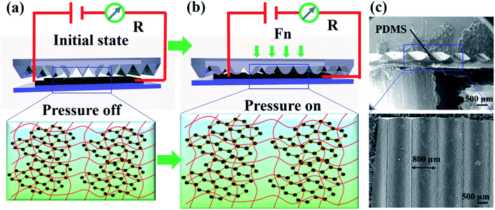 | ||
| Fig. 6 (a and b) The sensitive mechanism model of the flexible pressure sensor; (c) SEM of encapsulation layer microstructure. | ||
3.3 Application of flexible pressure sensor motion capture
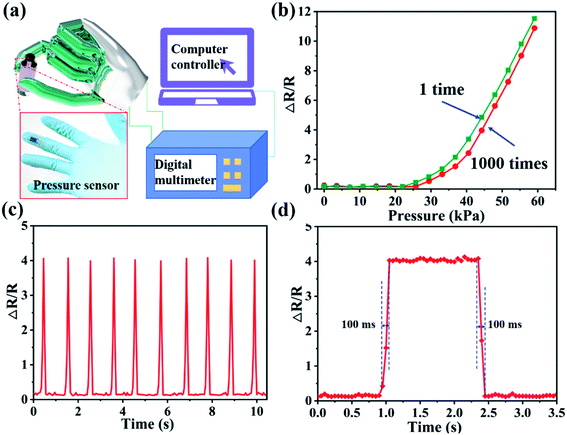
A flexible pressure sensor (L × W × H: 20 mm × 10 mm × 500 μm) with a multi-bend structure was fabricated, and attached it to the finger for object catching test (Fig. 7a). The repeated application of pressure of 0–60 kPa to the pressure–sensitive structure was investigated, and obtained the pressure–sensitive characteristic curves of the pressure applied 1 and 1000 times, respectively. As shown in Fig. 7b, the two characteristic curves maintained the same slope, which verifies that the single pressure–sensitive structure has good reliability and stability. In addition, a load of 40 kPa was applied to the sensitive unit to perform continuous loop test experiments, as shown in Fig. 7c. The value of ΔR/R remained stable during each pressure application process. The response and recovery time of the flexible pressure sensor were investigated to characterize the pressure-sensitive response characteristics under the application of external pressure of 40 kPa (Fig. 7b). The resistance responds quickly when external pressure was applied. The resistance immediately returns to the initial value when the external pressure was removed. During the loading and unloading of external pressure, the response/recovery time was increased to 100 ms and 100 ms, respectively. It showed that the pressure-sensitive structure of the flexible sensor has excellent response characteristics.We demonstrated the motion capture experiments on glass bottles, batteries, and glass plates to verify the application potential of flexible pressure sensors on human prostheses, as shown in Fig. 8a–f. When grabbing a glass bottle with a weight of 19.58 g, the sensor's ΔR/R changed by ∼3; when the glass bottle was filled with 14.37 g of water, the grab action test was performed, and its ΔR/R changed by ∼7.6. This experiment demonstrates that the sensor has the ability to accurately distinguish objects of different qualities (Fig. 8a–c). Further, we tested the sensitivity of grabbing objects of similar quality on different surfaces. Compared with the flat glass plate, the sensor ΔR/R of the curved shape battery has a larger change. The possible reason was that when grabbing a curved object, the curved surface increases the strain of the sensor's sensitive unit, resulting in an increase in the resistance change. Therefore, when grasping a curved object, the sensor has a small force area and a strong pressure, resulting in a large change in resistance, so it shows higher sensitivity (Fig. 8d–f).
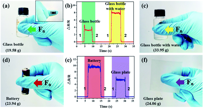 | ||
| Fig. 8 (a–c) Motion capture applications of different quality and (d–f) different surface objects. “1” and “2” represent the process of grabbing and placing. | ||
When grabbing an object, the thumb pressure Fn was applied to the sensor, and the resistance value changes due to the deformation of the sensor. When the gripping action was maintained, the resistance of the sensor remained constant, indicating that the sensor has good stability. However, when the object was released, the resistance of the sensor returns to the initial value, which shows that the sensor has a quick response to the action. In addition, at the moment of grasping and placing an object, the resistance of the sensor suddenly increased due to the extra force exerted by the thumb. It shows that the sensor has excellent feedback on the pressure generated by the action details.
In this work, we connected the sensor to the digital multimeter through wires for operation testing, which interfered with the response characteristics of the pressure-sensitive structure to a certain extent. As a wearable electronic device, its wiring part needs to be removed to realize its wireless operations. Recent paper demonstrated the fully wireless operations of the pressure sensor array through integration with bluetooth and batteries, realizing the progress from wired operation to wireless integration.37,38 In the future, we will integrate the function of completely wireless operation into the flexible pressure sensor device to achieve the integration of function and structure.
4 Conclusion
In this paper, a flexible pressure sensor with GNPs/MWCNT composite material was fabricated using direct-write printing technology based on Weissenberg principle. The continuous rotation of the microneedles produced the Weissenberg effect, which could efficiently transport the solution and avoid the agglomeration of GNPs/MWCNT. The parameters affecting the manufacture of sensitive structures were optimized through orthogonal experiments. Next, we fabricated a pressure-sensitive structure with multiple bending structures, and tested the sensitivity (0.164 kPa−1) and response/recovery time (100 ms/100 ms). Finally, a flexible pressure sensor to the finger was attached to grab objects of different qualities and different surfaces, demonstrating its application in the field of artificial prostheses and rehabilitation robots in the future.Conflicts of interest
There are no conflicts to declare.Acknowledgements
This work was supported by the Guangdong Basic and Applied Basic Research Foundation (2019A1515110637), Guangdong University Young Innovative Talent Project (2019KQNCX076), Lingnan Normal University Scientific Research Project (No. ZL2026), National Natural Science Foundation of China (51705228), National Science Foundation of Guangdong Province (2020A1515010165).References
- K. Dong, Z. Wu, J. Deng, A. C. Wang, H. Zou, C. Chen, D. Hu, B. Gu, B. Sun and Z. L. Wang, Adv. Mater., 2018, 30, e1804944 CrossRef PubMed.
- S. Choi, H. Lee, R. Ghaffari, T. Hyeon and D. H. Kim, Adv. Mater., 2016, 28, 4203–4218 CrossRef CAS PubMed.
- A. Chortos, J. Liu and Z. Bao, Nat. Mater., 2016, 15, 937–950 CrossRef CAS PubMed.
- S. Jung, J. H. Kim, J. Kim, S. Choi, J. Lee, I. Park, T. Hyeon and D. H. Kim, Adv. Mater., 2014, 26, 4825–4830 CrossRef CAS PubMed.
- J. K. Donghee Son and O. Vardoulis, et al., Nat. Nanotechnol., 2018, 13, 1057–1065 CrossRef PubMed.
- C. Wang, C. Pan and Z. Wang, ACS Nano, 2019, 13, 12287–12293 CrossRef CAS PubMed.
- S. Wang, J. Xu and W. Wang, et al., Nature, 2018, 555, 83–88 CrossRef CAS PubMed.
- Y. Ma, Y. Yue, H. Zhang, F. Cheng, W. Zhao, J. Rao, S. Luo, J. Wang, X. Jiang and Z. Liu, ACS Nano, 2018, 12, 3209–3216 CrossRef CAS PubMed.
- D. J. Lipomi, M. Vosgueritchian, B. C. Tee, S. L. Hellstrom, J. A. Lee, C. H. Fox and Z. Bao, Nat. Nanotechnol., 2011, 6, 788–792 CrossRef CAS PubMed.
- T. Q. Trung and N. E. Lee, Adv. Mater., 2016, 28, 4338–4372 CrossRef CAS PubMed.
- L. Pan, A. Chortos, G. Yu, Y. Wang, S. Isaacson, R. Allen, Y. Shi, R. Dauskardt and Z. Bao, Nat. Commun., 2014, 5, 3002 CrossRef PubMed.
- J. Wang, J. Jiu, M. Nogi, T. Sugahara, S. Nagao, H. Koga, P. He and K. Suganuma, Nanoscale, 2015, 7, 2926–2932 RSC.
- Z. Lou, S. Chen, L. Wang, K. Jiang and G. Shen, Nano Energy, 2016, 23, 7–14 CrossRef CAS.
- C.-L. Choong, M.-B. Shim, B.-S. Lee, S. Jeon, D.-S. Ko, T.-H. Kang, J. Bae, S. H. Lee, K.-E. Byun and J. Im, Adv. Mater., 2014, 26, 3451–3458 CrossRef CAS PubMed.
- J. Park, Y. Lee, J. Hong, Y. Lee, M. Ha, Y. Jung, H. Lim, S. Y. Kim and H. Ko, ACS Nano, 2014, 8, 12020–12029 CrossRef CAS PubMed.
- C. Pang, G. Y. Lee, T. I. Kim, M. K. Sang, N. K. Hong, S.-H. Ann and K.-Y. Sun, Nat. Mater., 2012, 11, 795–801 CrossRef CAS PubMed.
- J. Jang, H. Kim, S. Ji, H. J. Kim, T. S. Kim, M. S. Kang, T. S. Kim, J. Won, J. H. Lee, J. Cheon, K. Kang, W. B. Im and J. U. Park, Nano Lett., 2020, 20, 66–74 CrossRef CAS PubMed.
- B. Zhu, Z. Niu, H. Wang, R. L. Wan and X. Chen, Small, 2014, 10, 3625–3631 CrossRef CAS PubMed.
- S. C. B. Mannsfeld, C. K. Tee, R. M. Stoltenberg, H. H. Chen, S. Barman, B. V. O. Muir, A. N. Sokolov, C. Reese and Z. Bao, Nat. Mater., 2010, 9, 859–864 CrossRef CAS PubMed.
- S. Y. Kim, S. Park, H. W. Park, D. H. Park, Y. Jeong and D. H. Kim, Adv. Mater., 2015, 27, 4178–4185 CrossRef CAS PubMed.
- K. K. Shingo Harada, Y. Yamamoto, T. Arie, S. Akita and K. Takei, ACS Nano, 2014, 8, 12851–12857 CrossRef PubMed.
- B. Zhu, H. Wang, Y. Liu, D. Qi, Z. Liu, H. Wang, J. Yu, M. Sherburne, Z. Wang and X. Chen, Adv. Mater., 2016, 28, 1559–1566 CrossRef CAS PubMed.
- X. Wang, Y. Gu, Z. Xiong, Z. Cui and T. Zhang, Adv. Mater., 2014, 26, 1336–1342 CrossRef CAS PubMed.
- Y. S. Rim, S. H. Bae, H. Chen, N. De Marco and Y. Yang, Adv. Mater., 2016, 28, 4415–4440 CrossRef CAS PubMed.
- J. T. Muth, D. M. Vogt, R. L. Truby, Y. Menguec, D. B. Kolesky, R. J. Wood and J. A. Lewis, Adv. Mater., 2014, 26, 6307–6312 CrossRef CAS PubMed.
- S. Ryu, P. Lee, J. B. Chou, R. Xu and S. G. Kim, ACS Nano, 2015, 9, 5929 CrossRef CAS PubMed.
- J. H. K. Changhyun Pang, A. Nguyen, J. M. Caves, M.-G. Kim, K. K. Alex Chortos, P. J. Wang, J. B.-H. Tok and Z. Bao, Adv. Mater., 2015, 27, 634–640 CrossRef PubMed.
- J. Y. Peng and S. C. Lu, IEEE Sensor. J., 2015, 15, 1170–1177 Search PubMed.
- X. Guo, W. Wang, Y. Yang and Q. Tian, CrystEngComm, 2016, 18, 9033–9041 RSC.
- S. Peng, P. G. Hartley, T. C. Hughes and Q. Guo, Soft Matter, 2012, 8, 10493 RSC.
- Q. Chen, X. Mei, S. Zhe, D. Wu, Z. Yang, L. Wang, X. Chen, G. He, Y. Zhe and F. Ke, Opt. Lett., 2017, 42, 5106 CrossRef CAS PubMed.
- Y. Luo, D. Wu, Y. Zhao, Q. Chen, Y. Xie, M. Wang, L. Lin, L. Wang and D. Sun, Org. Electron., 2019, 67, 10–18 CrossRef CAS.
- X. Mei, Q. Chen, S. Wang, W. Wang and D. Sun, Nanoscale, 2018, 10, 7127–7137 RSC.
- Y. Luo, P. Qianqian, Z. Yuchao, W. Guangshun, W. Dezhi, Z. Rui, X. Yu and S. Daoheng, J. Mech. Eng., 2019, 55, 90 CrossRef.
- Y. Shu, H. Tian, Y. Yang, C. Li, Y. Cui, W. Mi, Y. Li, Z. Wang, N. Deng, B. Peng and T. L. Ren, Nanoscale, 2015, 7, 8636–8644 RSC.
- S. H. Hwang, H. W. Park and Y. B. Park, Smart Mater. Struct., 2012, 22, 015013 CrossRef.
- H. Kou, L. Zhang, Q. Tan, G. Liu, H. Dong, W. Zhang and J. Xiong, Sci. Rep., 2019, 9, 3916 CrossRef PubMed.
- W. H. Cheong, B. Oh, S.-H. Kim, J. Jang and J.-U. Park, Nano Energy, 2019, 62, 230–238 CrossRef CAS.
| This journal is © The Royal Society of Chemistry 2020 |

