 Open Access Article
Covalent polymer functionalized graphene oxide/poly(ether ether ketone) composites for fused deposition modeling: improved mechanical and tribological performance
Cheng Yang*,
Jing Xu *,
Yue Xing,
Sijia Hao and
Zhidong Ren
Research Center of Graphene Applications, Beijing Institute of Aeronautical Materials, Haidian District, Beijing 100095, China. E-mail: chengyang_78@126.com; xjbreeze@foxmail.com
First published on 7th July 2020
Abstract
This paper presents a novel method using poly(aryl ether ketone) containing pendant carboxyl groups to covalently functionalize graphene oxide. The functionalized graphene oxide (LFG) was used to prepare poly(ether ether ketone) (PEEK) composites through melt blending. It is found that LFG has great interface adhesion to the PEEK matrix, and just a small amount of it can simultaneously improve the strength and toughness of the composites, while unmodified graphene oxide could enhance strength but cause toughness damage. The tensile and impact strength of composite with 0.1 wt% LFG are 5.7% and 20.5% higher than that of neat PEEK, respectively. In addition, 0.5 wt% LFG composite shows great friction and wear performance with friction coefficient and specific wear rate 27.3% and 18.3% lower than that of PEEK. Furthermore, the composites can be used as practical high-performance additive manufacturing materials because LFG is able to improve the mechanical performance of the fused deposition modeling (FDM) composite samples significantly.
1. Introduction
Poly(ether ether ketone) (PEEK) is a semi-crystalline special engineering plastic which has been widely used in aerospace, machinery, chemical industry and biomedicine, owing to its high performance, excellent mechanical properties, chemical resistance, thermal stability and self-lubrication properties.1–3 To further enhance its properties, fillers such as carbon fibers, carbon nanotubes, and various nanoparticles have been introduced to the PEEK matrix.4–6 Graphene has been widely used as a filler for polymer composites recently due to its excellent mechanical, electrical and thermal properties, even a very low addition amount can make a great significance.7,8 According to the literature, it is very promising to use graphene to improve the performance of PEEK composites, such as mechanical properties, thermal behaviour and tribological performance. Tewatia et al.9 found that the addition of graphene to PEEK could induce surface crystallization, increase crystallinity, and improve thermal stability. Recent literature of Lynch-Branzoi et al.10 demonstrated a approach to produce graphene enhanced PEEK composites using in situ shear exfoliation of graphite directly within molten polymer. The resultant composite showed a nearly 400% increase in tensile modulus. Song et al.11 showed that graphene oxide nanosheets could greatly improve the wear resistance of PEEK under boundary lubrication attributed to their small size and extremely thin laminated structure.The performance of graphene/PEEK composites depends to a large extent on whether graphene is homogeneously dispersed in PEEK matrix and the interfacial compatibility between graphene and PEEK. However, due to the high melting point and large melt viscosity of PEEK, as well as the high interfacial energy and weak interface binding force between PEEK and graphene, graphene tends to agglomerate in PEEK matrix and is difficult to disperse uniformly.9 By covalent or noncovalent modification of graphene, the interfacial compatibility of which with the PEEK matrix can be improved. For instance, Yang et al.12 coated the surface of thermally reduced graphene oxide (TRG) nanosheets with a layer of polyethersulfone (PES) to improve the interfacial adhesion between graphene and PEEK. The modification improved the dispersion uniformity and interfacial interaction of modified TRG and PEEK, and the resultant composites showed better mechanical and thermal properties. Song et al.13 covalently modified graphene oxide (GO) with γ-aminopropyl trimethoxysilane to make interfacial adhesion improvement through silane coupling agent. They found out that the modified GO composites had better friction and anti-wear performance than that filled with pristine GO and MWNTs because of the good dispersion of modified GO in PEEK. However, in the case of physically coating a layer of polymer on the surface of graphene or other non-covalent modification ways, the binding force between PEEK matrix and graphene is not substantially improved. As for the covalent functionalization of silane coupling agent, the chemical structure of most of the silane coupling agents and PEEK structural unit are of considerable difference, and there is decomposition risk during high temperature processing for silane coupling agent functionalized GO,14 so the result of this kind of modification is also not very satisfactory. To solve this problem, we develop a new method that use soluble poly(aryl ether ketone) containing pendant carboxyl groups (PEK-L) which has similar chemical structure and compatibility with PEEK15,16 to covalently modify GO via the “graft to” method.17 By this way, we expect to enhance the compatibility and interfacial adhesion between PEK-L functionalized GO (LFG) and PEEK, thus improving the performance of LFG/PEEK composites.
Additive manufacturing (AM), also known as 3D printing, is a manufacturing method that is increasingly valued by the scientific and engineering community, which has many advantages such as customized geometry, cost effective and time saving.18–20 Fused deposition modeling (FDM) is one of the most commonly used printing methods due to its low cost and great industrial application potential.21 FDM method requires to melt filament form material and extrude through a nozzle, then deposite it onto a buildplate layer by layer to generate three-dimensional structure.22 One of the largest obstacles for practical using of FDM parts is that the mechanical properties of them are generally worse than parts processed by traditional techniques such as injection molding because of more structure defects.23,24 PEEK FDM parts are also no exception,25,26 so it is necessary to develop printable PEEK composite materials with higher performance to improve the limited mechanical performance of printed PEEK parts.
In this work, graphene oxide was firstly functionalized with diisocyanate, then reacted with PEK-L via a facile “graft to” method to obtain LFG, which was used to prepare LFG/PEEK composites by melt blending method. The influences of LFG on mechanical properties of composites and its difference with unmodified GO were investigated. In addition, the tribological behavior of LFG/PEEK composites was studied. Finally, the LFG/PEEK composites were processed into filaments used for FDM, and the tensile performance of composite FDM samples was investigated.
2. Experimental
2.1. Materials
Chemical reagents were used without further purification unless stated otherwise. PEEK powder (550PF, dp ∼ 48 μm, Mn ∼ 36![[thin space (1/6-em)]](https://www.rsc.org/images/entities/char_2009.gif) 000 g mol−1), purchased from Jilin Zhongyan Polymer Materials Co. Ltd, China, was vacuum dried at 150 °C for 3 h before use. Toluene-2,4-diisocyanate (TDI) and phenolphthalein (PPL) were supplied by Tokyo Chemical Industry Co. Ltd. Dibutyltindilaurate (DBTDL) was purchased from J&K Scientific. 4,4′-Difluorobenzophenone (DFBP) was provided by Aladdin. Potassium carbonate, toluene, anhydrous dimethylformamide (DMF), dimethylsulfoxide (DMSO) and acetone were supplied by Sinopharm Chemical Reagent Co. Ltd.
000 g mol−1), purchased from Jilin Zhongyan Polymer Materials Co. Ltd, China, was vacuum dried at 150 °C for 3 h before use. Toluene-2,4-diisocyanate (TDI) and phenolphthalein (PPL) were supplied by Tokyo Chemical Industry Co. Ltd. Dibutyltindilaurate (DBTDL) was purchased from J&K Scientific. 4,4′-Difluorobenzophenone (DFBP) was provided by Aladdin. Potassium carbonate, toluene, anhydrous dimethylformamide (DMF), dimethylsulfoxide (DMSO) and acetone were supplied by Sinopharm Chemical Reagent Co. Ltd.
2.2. Preparation of TDI modified GO (GO-TDI)
GO was synthesized by modified Hummers method in laboratory.27 To prepare GO-TDI, 500 mg GO was suspended in 200 mL anhydrous DMF, and sonicated in an ultrasonic bath for 30 min. Subsequently, 10 g TDI and 50 mL DMF were put into a three-neck flask and ultra-sonicated for 5 minutes. The flask equipped with constant pressure dropping funnel and N2 vessel was put into oil bath and the temperature was kept at 30 °C. After that, the GO suspension and 0.2 mL DBTDL catalyst were added into the dropping funnel, dropped at a constant speed with stirring in 2 hours. The reaction was finished after another 8 hours, and the obtained mixture was filtered through a 0.45 μm polyvinylidene fluoride microporous membrane filter, and washed with anhydrous DMF three times to obtain GO-TDI. A small amount of GO-TDI for characterization was washed with acetone for 3 times, then dried at 80 °C for 3 h in a vacuum oven, and immediately placed in a sealed tube and stored in the dark environment.2.3. Preparation of LFG
The as prepared GO-TDI was put into a 500 mL three-necked bask immediately, and uniformly dispersed in 100 mL of anhydrous DMF by sonicating 10 min. PEK-L was prepared by methods described in the previous literature.15 1.5 g PEK-L was dissolved in 150 mL anhydrous DMF, and then added to the flask. After sonicating for 30 min, the flask was put into oil bath and the reaction was carried out at 120 °C for 8 h. After cooling, it was filtered and washed 3 times with DMF and then 3 times with acetone. After drying in a vacuum oven at 80 °C for 3 h, LFG was obtained.2.4. Preparation of LFG/PEEK composites
1 g LFG and 500 mL acetone were sonicated for 30 min to achieve uniform dispersion, then mixed with proportional PEEK powder under vigorous mechanical stirring for 15 min to obtain LFG/PEEK composites with LFG loading amount of 0.1%, 0.3%, 0.5%, 0.7% and 1.0% (weight fraction). The mixture was filtered and put into vacuum oven to dry at 80 °C for 2 h, and dried for another 3 h with the temperature raised to 150 °C. After that, the mixed powder was added to a twin-screw extruder to prepare LFG/PEEK composite masterbatch using melt blending method with a processing temperature range of 360 °C to 370 °C. The composites were denoted as 0.1LFG/PEEK, 0.3LFG/PEEK, 0.5LFG/PEEK, 0.7LFG/PEEK, 1.0LFG/PEEK, respectively. For comparison, unmodified GO and PEEK composites were prepared with GO content consistent with LFG, and were denoted as 0.1GO/PEEK, 0.3GO/PEEK, 0.5GO/PEEK, 0.7GO/PEEK and 1.0GO/PEEK. Pure PEEK powder was also subjected to the above procedure. The test samples of LFG/PEEK composites were prepared by injection molding.2.5. Fabrication of LFG/PEEK filaments and FDM process
The obtained LFG/PEEK powder mixture can be also extruded to prepare filaments used for FDM with a diameter of 1.75 mm. The optimal parameters of FDM process were as follows: the nozzle size was 0.4 mm, layer thickness was 0.2 mm, printing speed was set to be 20–40 mm s−1. The nozzle temperature, buildplate temperature and chamber temperature were 390, 150, and 70 °C, respectively.2.6. Characterization
The morphologies were observed on scanning electron microscope (SEM, FEI Nova NanoSEM 50) with an accelerating voltage of 15 kV and field-emission transmission electron microscopy (TEM, FEI Tecnai G2 F30). Fourier transform infrared (FTIR) spectra were collected using Nicolet IS10 FTIR spectrometer. The Raman spectra were performed on Renishaw inVia Raman spectrometer with He–Ne laser excited at 632.8 nm. X-ray photoelectron spectroscopy (XPS) was conducted on Thermo ESCALAB 250Xi with Al Kα excitation radiation. X-ray diffraction patterns were carried out using a Bruker D8 advance device with a 1.54 Å Cu Kα radiation source. Differential scanning calorimetry (DSC) was performed by a DSC Q200 instrument, and thermogravimetric analysis (TGA) data were collected on a NETZSCH STA 449 F3 instrument with N2 atmosphere at a heating/cooling rate of 10 °C min−1. Tensile, flexural, and impact tests were tested on the Instron mechanical testing machine, according to the ISO527-1, ISO178, and ISO180 respectively. The friction and wear properties were evaluated on a universal tribotester (GMP-30, Jinan Hengxu Tribological Testing Technology Co. Ltd., China). Sliding was performed at ambient temperature for 2 h at a sliding speed of 0.419 m s−1 with a load of 196 N. Before each test, the steel ring and samples were all cleaned with acetone.3. Results and discussion
The synthesis scheme of GO-TDI, PEK-L and LFG is shown in Fig. 1a. The hydroxyl and carboxyl groups of GO can react with one of the isocyanate groups of TDI under the catalysis of DBTDL due to the excessive addition of TDI and the different reactivity of two isocyanates in TDI.28 The para-isocyanate groups of TDI preferentially reacts with the hydroxyl and carboxyl groups of GO to form carbamate and amide structure, respectively, leaving the ortho-isocyanate groups unreacted due to larger steric hindrance. This allows unreacted isocyanate groups to attach to GO for further reaction without forming a crosslinked structure.29 The synthesis of PEK-L is carried out through the polycondensation reaction between PPL and DFBP in the presence of potassium carbonate.30 PEK-L is a non-crystalline thermoplastic polymer soluble in polar solvents such as dimethylsulfoxide (DMSO) and dimethylformamide (DMF),31,32 which makes the subsequent reaction easier because GO-TDI also has a good dispersion in DMF. Therefore, the pendant carboxyl groups of PEK-L can react with the active isocyanate groups of GO-TDI in DMF media to form a covalent linkage to obtain LFG. The preparation and FDM process of LFG/PEEK composites are shown in Fig. 1b. The PEEK powder was uniformly mixed with LFG nanosheets by ultrasonic dispersion and mechanical stirring, and then the LFG/PEEK composite was prepared by melt blending. Since PEK-L was covalently grafted on the modified GO and its structure is similar to that of PEEK, the interfacial adhesion between PEEK and GO can be improved. At the same time, the mixed powder of LFG and PEEK can also be directly used to extrude into filaments for FDM process.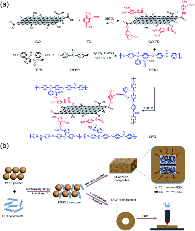 | ||
| Fig. 1 Schematic representation of (a) synthesis of GO-TDI, PEK-L and LFG; (b) preparation of LFG/PEEK composites and FDM process. | ||
3.1. Characterization of synthesized GO, GO-TDI, PEK-L and LFG
A variety of methods were used to characterize the synthesized GO, GO-TDI, PEK-L, and LFG. Fig. 2 shows the morphologies of GO, GO-TDI, and LFG observed by SEM and TEM micrographs. Fig. 2a and d show that GO nanosheets are ultrathin and transparent, with typical wrinkles observed. Compared to the unmodified GO, GO-TDI has a slight increase in thickness, as Fig. 2b and e show, which may be due to slight stacking or cross-linking between the GO sheets. After grafting PEK-L on the surface, it can be clearly seen from Fig. 2c and e that a layer of polymer appears on the sheets, and the thickness of the sheets is significantly increased. Besides, the typical wrinkle appearance of GO is no longer apparent. These all indicate that the modified GO sheets were successfully covered by a layer of PEK-L polymer. Fig. 3a shows the FT-IR spectra of GO, GO-TDI, LFG and PEK-L. FTIR spectrum of GO shows peaks at 1732 cm−1 (C![[double bond, length as m-dash]](https://www.rsc.org/images/entities/char_e001.gif) O stretch attributed to carboxyl and carbonyl groups), 1621 cm−1 (C
O stretch attributed to carboxyl and carbonyl groups), 1621 cm−1 (C![[double bond, length as m-dash]](https://www.rsc.org/images/entities/char_e001.gif) C vibration of graphitic domains), 1379 cm−1 (O–H bending vibration) and 1062 cm cm−1 (C–O stretch of epoxy groups), which indicates that the prepared GO is rich in oxygen-containing functional groups.32,33 In the spectrum of GO-TDI, the carboxyl stretch peak at 1732 cm−1 disappears, and the hydroxyl peak at 1379 cm−1 becomes less intense. Meanwhile, the C
C vibration of graphitic domains), 1379 cm−1 (O–H bending vibration) and 1062 cm cm−1 (C–O stretch of epoxy groups), which indicates that the prepared GO is rich in oxygen-containing functional groups.32,33 In the spectrum of GO-TDI, the carboxyl stretch peak at 1732 cm−1 disappears, and the hydroxyl peak at 1379 cm−1 becomes less intense. Meanwhile, the C![[double bond, length as m-dash]](https://www.rsc.org/images/entities/char_e001.gif) O and C–O stretch peaks of the carbamate appear at 1704 and 1253 cm−1, respectively, and 1644 and 1538 cm−1 are the C
O and C–O stretch peaks of the carbamate appear at 1704 and 1253 cm−1, respectively, and 1644 and 1538 cm−1 are the C![[double bond, length as m-dash]](https://www.rsc.org/images/entities/char_e001.gif) O stretch peak and –NH in-plane bending vibration peak of amide. Notably, the stretching peak of –NCO groups at 2273 cm−1 is observed,34,35 though the absorption peak is weak, which may due to the reaction consumption of active –NCO with H2O and CO2 in the air. These facts confirm that some amount of –OH and –COOH groups of GO were consumed by reaction with TDI, and –NCO groups were successfully attached to GO sheets. In the spectrum of PEK-L, the peaks at 1721 cm−1 and 1696 cm−1 are assigned to the C
O stretch peak and –NH in-plane bending vibration peak of amide. Notably, the stretching peak of –NCO groups at 2273 cm−1 is observed,34,35 though the absorption peak is weak, which may due to the reaction consumption of active –NCO with H2O and CO2 in the air. These facts confirm that some amount of –OH and –COOH groups of GO were consumed by reaction with TDI, and –NCO groups were successfully attached to GO sheets. In the spectrum of PEK-L, the peaks at 1721 cm−1 and 1696 cm−1 are assigned to the C![[double bond, length as m-dash]](https://www.rsc.org/images/entities/char_e001.gif) O absorption of the free carboxyl groups and the hydrogen-bonded carboxyl groups respectively. The stretching vibration peak of the aromatic ketone carbonyl groups is at 1652 cm−1, the C
O absorption of the free carboxyl groups and the hydrogen-bonded carboxyl groups respectively. The stretching vibration peak of the aromatic ketone carbonyl groups is at 1652 cm−1, the C![[double bond, length as m-dash]](https://www.rsc.org/images/entities/char_e001.gif) C stretching vibration peaks of the benzene ring are at 1591 cm−1 and 1496 cm−1, and Ar–O–Ar stretching vibration peak is at 1233 cm−1. These absorption peaks all correspond to the structural units of PEK-L, and is consistent with the literature,15,30 indicating it's successful synthesis. The LFG spectrum is quite similar to that of the PEK-L, which suggests that PEK-L covered at the surface of the modified graphene oxide and masked its peak signals. The difference between LFG and the PEK-L in the spectra is that the carboxyl peaks of 1721 cm−1 and 1696 cm−1 are no longer obvious, which demonstrating that partial carboxyl groups of PEK-L had been reacted with –NCO groups, and the –C
C stretching vibration peaks of the benzene ring are at 1591 cm−1 and 1496 cm−1, and Ar–O–Ar stretching vibration peak is at 1233 cm−1. These absorption peaks all correspond to the structural units of PEK-L, and is consistent with the literature,15,30 indicating it's successful synthesis. The LFG spectrum is quite similar to that of the PEK-L, which suggests that PEK-L covered at the surface of the modified graphene oxide and masked its peak signals. The difference between LFG and the PEK-L in the spectra is that the carboxyl peaks of 1721 cm−1 and 1696 cm−1 are no longer obvious, which demonstrating that partial carboxyl groups of PEK-L had been reacted with –NCO groups, and the –C![[double bond, length as m-dash]](https://www.rsc.org/images/entities/char_e001.gif) O stretch of the amide obtained by the reaction was overlapped by that of the aromatic ketone carbonyl groups at 1651 cm−1.36
O stretch of the amide obtained by the reaction was overlapped by that of the aromatic ketone carbonyl groups at 1651 cm−1.36
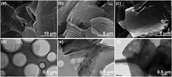 | ||
| Fig. 2 Morphology images of GO and chemically modified GO. (a–c) SEM images of GO, GO-TDI, LFG, respectively; (d–f) TEM images of GO, GO-TDI, LFG, respectively. | ||
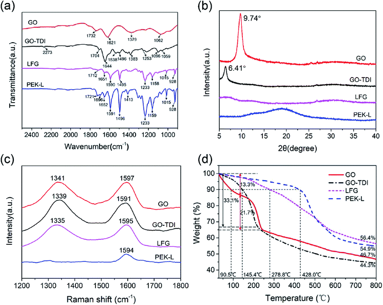 | ||
| Fig. 3 Characterization of GO, GO-TDI, PEK-L and LFG. (a) FTIR spectra; (b) Raman spectra; (c) XRD patterns; (d) thermogravimetric curves. | ||
Fig. 3b presents the XRD patterns of GO, GO-TDI, PEK-L and LFG. The diffraction peak of GO shows a 2θ value of 9.74° corresponding to d spacing of 0.91 nm. No feature peak of natural graphite around 26° is observed at GO pattern, suggesting the fully exfoliation of graphite.37 GO-TDI shows a diffraction peak at 6.41°, which indicates that with the modification of TDI, the interplanar spacing between the sheets increases. The broad XRD peak for PEK-L is a typical amorphous polymer diffraction peak.15 After the covalent grafting of PEK-L on the GO-TDI surface, its ordered stacking structure no longer exists with no diffraction peak shown in the LFG pattern, which further proves the successful grafting of PEK-L.
Fig. 3c gives the Raman spectra of GO, GO-TDI and LFG. GO spectrum shows the peak at 1597 cm−1 (G band) corresponds to the in-plane vibration of sp2 carbon atoms, and the peak at 1341 cm−1 (D band) is characteristic disorder and defects induced bands.38,39 The small frequency red shift about 6 cm−1 of G band for GO-TDI is observed compared with GO, indicating structural change of GO during chemical functionalization, which can be explained by the reduction of GO during the reaction between oxygen-containing functional groups and TDI.29,40 After grafting with PEK-L, the G band of LFG is found to be blue-shifted slightly, combined with the peak at 1594 cm−1 in the PEK-L spectrum corresponding to the C![[double bond, length as m-dash]](https://www.rsc.org/images/entities/char_e001.gif) C vibration peak of the benzene ring,41 which suggests the structural change after the modification of PEK-L. The ID/IG values of GO, GO-TDI and LFG are calculated to be 1.13, 1.14, and 1.08, respectively, indicating similar defect number in the three materials.32
C vibration peak of the benzene ring,41 which suggests the structural change after the modification of PEK-L. The ID/IG values of GO, GO-TDI and LFG are calculated to be 1.13, 1.14, and 1.08, respectively, indicating similar defect number in the three materials.32
Fig. 3d shows the thermogravimetric curves of GO, GO-TDI, PEK-L and LFG. The 10% weight loss temperature of GO, GO-TDI and LFG are 90.5 °C, 145.4 °C, 278.8 °C, respectively, namely the initial decomposition temperature increased as the sequent modification went. The thermal decomposition behavior of GO-TDI is more similar to that of GO, but GO has an extra fast decomposition stage at the beginning. This may be due to GO has more absorbed water and GO-TDI has less –OH and –COOH groups.42 LFG maintains a slower and steady decomposition rate within the whole temperature range, and shows much better thermal stability and residual mass (56.4%) at 800 °C than GO (46.7%) and GO-TDI (44.3%) because of the grafting of heat-resistant PEK-L polymer.
The elemental composition and chemical structure of GO, GO-TDI, LFG and PEK-L were analyzed by XPS, and the survey scan patterns are shown in the Fig. 4a. Typically all the four materials show C1s and O1s peaks at ∼285 and ∼532 eV, and GO-TDI and LFG show additional N1s peaks at ∼400 eV. The elemental composition data is summarized in Fig. 4b. The percentages of C, O atoms in GO-TDI and GO are 70.9%, 19.2% and 62.0%, 38.0% respectively, the increase of C and decrease of O atom ratio of GO-TDI verify again that the oxygen-containing functional groups in GO react successfully with TDI. The O atomic percentage of PEK-L is 13.9%, which is very close to its theoretical value of 13.2%. The N atomic percentage of LFG is 4.3%, smaller than that of GO-TDI (9.9%), mainly because the introduction of C and O atoms of PEK-L. Fig. 4c shows the C1s spectra of the four substances. The C1s spectrum of GO is resolved into four peaks at 284.4, 286.8, 288.6, and 289.4 eV, corresponding to C![[double bond, length as m-dash]](https://www.rsc.org/images/entities/char_e001.gif) C/C–C, C–O, C
C/C–C, C–O, C![[double bond, length as m-dash]](https://www.rsc.org/images/entities/char_e001.gif) O, and O–C
O, and O–C![[double bond, length as m-dash]](https://www.rsc.org/images/entities/char_e001.gif) O contribution, respectively.43,44 With the modification of TDI, the peak of the C–N and C
O contribution, respectively.43,44 With the modification of TDI, the peak of the C–N and C![[double bond, length as m-dash]](https://www.rsc.org/images/entities/char_e001.gif) N at 285.8 eV is observed.45 Meanwhile, the intensity of C–O and O–C
N at 285.8 eV is observed.45 Meanwhile, the intensity of C–O and O–C![[double bond, length as m-dash]](https://www.rsc.org/images/entities/char_e001.gif) O decreases for the reaction of hydroxyl and carboxyl groups. PEK-L can be also deconvoluted into similar four peaks with GO, while LFG shows decreased peak intensity of O–C
O decreases for the reaction of hydroxyl and carboxyl groups. PEK-L can be also deconvoluted into similar four peaks with GO, while LFG shows decreased peak intensity of O–C![[double bond, length as m-dash]](https://www.rsc.org/images/entities/char_e001.gif) O and a new peak of C–N structure compared with PEK-L. The N1s peaks of GO-TDI and LFG are analyzed as shown in Fig. 4d. The N1s peak of GO-TDI can be deconvoluted into NH–CO (399.9 eV, including NH–COO structure) and O
O and a new peak of C–N structure compared with PEK-L. The N1s peaks of GO-TDI and LFG are analyzed as shown in Fig. 4d. The N1s peak of GO-TDI can be deconvoluted into NH–CO (399.9 eV, including NH–COO structure) and O![[double bond, length as m-dash]](https://www.rsc.org/images/entities/char_e001.gif) C
C![[double bond, length as m-dash]](https://www.rsc.org/images/entities/char_e001.gif) N structure (401.1 eV).34 As for LFG, the O
N structure (401.1 eV).34 As for LFG, the O![[double bond, length as m-dash]](https://www.rsc.org/images/entities/char_e001.gif) C
C![[double bond, length as m-dash]](https://www.rsc.org/images/entities/char_e001.gif) N peak disappears, only NH–CO peak remains. This also suggests that the isocyanate groups in GO-TDI successfully reacted with the carboxyl groups of PEK-L.
N peak disappears, only NH–CO peak remains. This also suggests that the isocyanate groups in GO-TDI successfully reacted with the carboxyl groups of PEK-L.
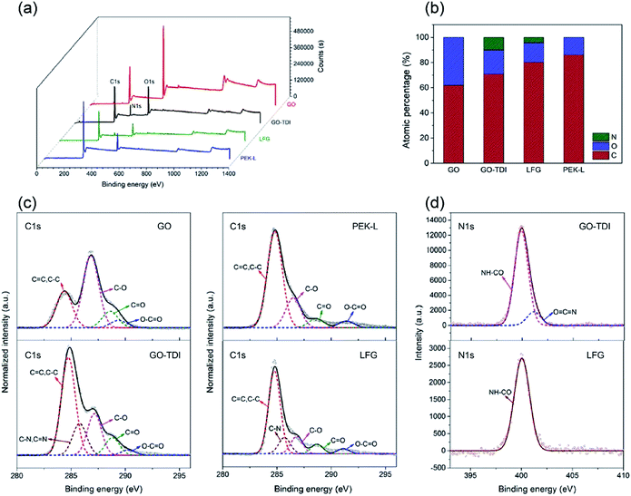 | ||
| Fig. 4 XPS analysis results of GO, GO-TDI, PEK-L and LFG. (a) XPS survey; (b) atomic composition; (c) C1s spectra; (d) N1s spectra. | ||
The characterization results above clearly prove that isocyanate groups have been attached to GO, and PEK-L has been fabricated and reacted with the isocyanate groups of GO-TDI successfully, so that PEK-L chemically functionalized GO was finally obtained.
3.2. Performance of LFG/PEEK composites
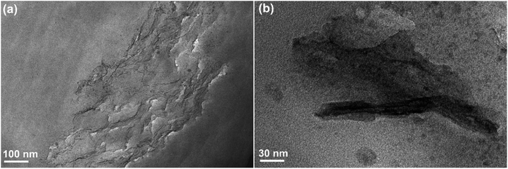
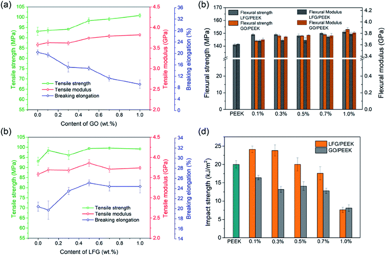
Fig. 5a and b show TEM ultrathin slice micrographs of 0.5GO/PEEK and 0.5LFG/PEEK composites respectively. It can be seen from Fig. 5a that GO is slightly aggregated in PEEK matrix, and the interface boundary of GO sheets and PEEK matrix is sharper than that of LFG and PEEK matrix in Fig. 5b, where very close interface is formed between the PEEK matrix and LFG nanosheet. It is shown that on the surface of the LFG sheet there is PEEK polymer, which is integrated with the polymer matrix, so that the interface is very obscure. During the cutting process of ultra-thin slices preparation, generally the fillers in composite material can be easily peeled off, but there is not even slight gap between LFG and PEEK matrix observed. These all indicate that LFG and PEEK matrix have great interfacial adhesion.Fig. 6 shows the mechanical properties of pure PEEK, GO/PEEK and LFG/PEEK composites. The tensile strength, tensile modulus and breaking elongation of GO/PEEK and LFG/PEEK composites are demonstrated at Fig. 6a and b. Fig. 6a shows that GO can improve the tensile strength and modulus of PEEK when the addition content is more than 0.3 wt%. However, the breaking elongation decreases with the addition amount of GO increases, which means the tensile toughness of GO/PEEK composites becomes worse. The result of Fig. 6b shows that the tensile strength, tensile modulus and elongation at break of LFG/PEEK composites are all improved after the addition of LFG, even a small amount of 0.1 wt% has obvious effect. There is little difference in tensile performance when LFG is added more than 0.5 wt%. For 0.5LFG/PEEK composite, the tensile strength, modulus and breaking elongation are 6.8%, 7.0%, and 31.6% higher than those of pure PEEK, respectively. The results indicate that LFG is capable of enhancing both tensile strength and toughness of PEEK matrix while GO has reinforcing effect but damages tensile toughness. Fig. 6c shows the flexural strength and modulus data of GO/PEEK and LFG/PEEK composites. The flexural strength and modulus of both composites are higher than that of neat PEEK. The composite 1.0LFG/PEEK presents flexural strength and modulus increased by 7.1% and 5.0% compared to neat PEEK. Fig. 6d shows the cantilever beam notched impact strength data of composites with different GO and LFG content. It is clearly shown that the impact strength results of GO/PEEK composites are all notably lower than that of neat PEEK, with a overall declining trend as GO amount rises. For LFG/PEEK composites, as the LFG amount increases, the impact strength is shown to increase at the beginning and then decrease. Composites with low LFG content like 0.1LFG/PEEK and 0.3LFG/PEEK, the impact strength increases by 20.5% and 19.0%, respectively. When LFG amount reaches 0.5%, it is quite close to that of pure PEEK. As the additive amount rises further (0.7 wt% and 1.0 wt%), the impact strength is shown to decrease. Note that for 0.1LFG/PEEK, the tensile strength and flexural strength rise by 5.7% and 5.4% compared to PEEK, so the mechanical results demonstrate that small amount of LFG would lead to great reinforcement and toughening effect simultaneously. In previous literature, it is frequently observed that the strength and stiffness of polymers were enhanced by graphene, but nearly always accompanying reduced toughness and ductility.9,46 In practical structural applications, strength and toughness are both very important to the structural engineering materials, so it is of great significance to accomplish simultaneous strengthening and toughening. The reason that GO and LFG can improve the composite strength may attribute to their confining of the motion of PEEK chains or segments, and the stress can be transferred to GO or LFG. However, due to the poor adhesion between GO and PEEK matrix, it is easy to have stress concentration around GO, resulting in poor toughness. In the case of LFG/PEEK composites, PEK-L macromolecular chains may play a role of “flexible connection” at the interface, make the concentrated stress dissipate during debonding process.47,48 Therefore, the grafted PEK-L has played a significant role in the enhanced strength and toughness of resultant composites. However, when large amount of LFG is added, it may restrict the molecular chain movement of polymer matrix and limit the polymer yielding, which is not beneficial to toughness improvement of the composites.49
The friction and wear properties under dry sliding condition of LFG/PEEK composites are shown in Fig. 7a–c. It is shown that the friction coefficient of LFG/PEEK composites are all lower than that of neat PEEK, whereas the coefficient is generally flat when adding amount is 0.5 wt% and further. The behavior of the specific wear rate performance shows a trend of decrease first and then slightly increase, all results are lower than pure PEEK except for the case of 0.1LFG/PEEK, whose specific wear rate is close to that of pure PEEK. The lowest fiction coefficient and specific wear rate is given by 0.5LFG/PEEK, 27.3% and 18.3% smaller than those of neat PEEK, which is a remarkable improvement. Fig. 8a–c show SEM images of the worn surfaces of neat PEEK and LFG/PEEK composites. The worn surface of the unfilled PEEK is rough, showing adhesive wear and plowing marks (Fig. 8a), which corresponds to relatively poorer friction and wear resistance performance of the neat PEEK. As small amount of LFG is added into the PEEK matrix, the friction surface of the composite is smoother than PEEK sample and shows very shallow wear track (Fig. 8b). A part of LFG is projecting from the friction surface, showing that it has tight adhesion with PEEK matrix. However, when the amount of LFG increases, some of LFG would be wore off, forming some small pits on the friction counterface, which would aggravate the abrasion (Fig. 8c). The decrease in friction coefficient may be due to the higher strength of the LFG/PEEK composite. LFG restricts the transfer of large quantities of PEEK macromolecules to the friction pair during adhesive wear process, but only a small amount of PEEK molecules transfer to the friction pair to form a thin and uniform transfer film, thereby reducing the surface roughness and reducing the friction coefficient.50,51 For the same reason, when the LFG addition content is low, less PEEK polymer can be taken away during adhesive wear process, so the specific wear rate declines. But when more LFG is added, some of the LFG could be wore off as abrasive grain, intensifying the abrasive wear, so the specific wear rate increases.52
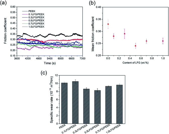 | ||
| Fig. 7 Sliding friction and wear performance of LFG/PEEK composites: (a) friction coefficient-sliding time curves; (b) mean friction coefficient; (c) specific wear rate. | ||
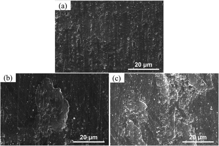 | ||
| Fig. 8 (a–c) SEM images of worn surfaces of LFG/PEEK composites: (a) PEEK; (b) 0.5LFG/PEEK; (c) 1.0LFG/PEEK. | ||
3.3. The additive manufacturing of LFG/PEEK composites
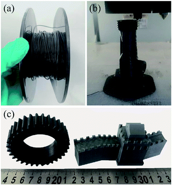
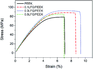
Filaments of neat PEEK and LFG/PEEK composite with different LFG ratio are successfully prepared, one of that is shown in Fig. 9a. Once the filament is obtained, it can be printed by employing a high temperature FDM 3D printer (Fig. 9b). PEEK is a semi-crystalline polymer with high melting temperature, so the process of crystallization behavior with temperature changes during printing increases the complexity of the printing process. During the printing process, rapid changes in the temperature field can result in uneven thermal stress distribution, causing defects such as warping and deformation in printed parts.25 The main printing parameters such as nozzle temperature, substrate temperature, chamber temperature, printing speed, and layer thickness should be considered in the printing process. The chamber temperature and printing speed are the main factors affecting the temperature field of the 3D printed sample. Therefore, under the condition of ensuring smooth 3D printing, increasing the chamber temperature and speeding up the printing speed can make the temperature field distribution of the sample more uniform, and improve the adhesive quality between layer and layer.53 After continuous exploration and optimization of process conditions, the optimal printing parameters of LFG/PEEK composites are found: nozzle temperature 390 °C, template temperature 150 °C, chamber temperature 90 °C, and print speed between 20–40 mm s−1. Smooth printing can be achieved under this condition, and the printed parts are free from warping. Fig. 9c shows some typical 3D printed models using LFG/PEEK composite filaments.The tensile performance of PEEK and low addition LFG/PEEK composites FDM samples were tested and shown in Fig. 10. The tensile strips were printed at 45°/45° raster angle in the XY plane with 100% filling ratio. Fig. 10 shows the representative tensile stress–strain curves. The tensile strength, modulus and breaking elongation of neat PEEK are 79.2 MPa, 3110 MPa, and 6.5% respectively, decreased by 14.9%, 13.4% and 63.2% compared to injection molded PEEK samples, namely a reduction of tensile mechanical property is presented when FDM method is used, consistent with previous literature results.25,26 This phenomenon can be greatly improved when a small amount of LFG is introduced. As shown from the figure, both 0.1LFG/PEEK and 0.3LFG/PEEK FDM samples show much better tensile performance than neat PEEK, and the tensile strength, modulus and breaking elongation of 0.3LFG/PEEK increase by 16.7%, 9.5% and 44.6% to 92.4 MPa, 3405 MPa, 9.4%. Nevertheless, when LFG content comes to 0.5 wt%, the tensile strength and breaking elongation begin to decrease. In summary, small amount of LFG can improve both the tensile strength and toughness of PEEK FDM parts, and the tensile strength of 0.3LFG/PEEK is even close to that of neat PEEK injection molding samples (93.1 MPa), compensating the loss of mechanical properties caused by FDM method. This has a great significance in broadening the practical engineering application of FDM parts, and the LFG/PEEK composite FDM parts are expected to be directly applied as end-use parts in fields like aerospace, automobile and machinery.
4. Conclusions
A series of LFG/PEEK composites with different filler contents were fabricated, and can be manufactured with fused deposition modeling method. The LFG filler, which has very good compatibility with PEEK matrix, was successfully prepared by covalently functionalizing GO through a facile “graft to” method. Just a small amount of LFG addition can strengthen and toughen the PEEK matrix simultaneously, while unmodified GO can improve the strength but reduce the toughness. The tensile, flexural and impact strength of 0.1LFG/PEEK are 5.7%, 5.4% and 20.5% higher than those of unfilled PEEK. In addition, LFG can reduce the friction coefficient and specific wear rate of the composites. For the 0.5LFG/PEEK, the friction coefficient and specific wear rate decrease by 27.3% and 18.3% than PEEK. The LFG/PEEK composites can be used as 3D printing materials for FDM, and parts with complex structure and excellent mechanical performance can be easily manufactured. The tensile strength and breaking elongation of 0.3LFG/PEEK FDM samples are 16.7% and 44.6% higher than those of PEEK, which can significantly broaden the application potential of FDM parts with intrinsically limited mechanical properties in a variety of engineering fields.Conflicts of interest
There are no conflicts of interest to declare.Acknowledgements
The authors acknowledge the Beijing Municipal Science and Technology Project (Z161100002116029) for financial support.References
- L. Jin, J. Ball, T. Bremner and H.-J. Sue, Polymer, 2014, 55, 5255–5265 CrossRef CAS.
- R. I. Shekar, T. M. Kotresh, P. M. D. Rao and K. Kumar, J. Appl. Polym. Sci., 2009, 112, 2497–2510 CrossRef CAS.
- S. M. Kurtz and J. N. Devine, Biomaterials, 2007, 28, 4845–4869 CrossRef CAS PubMed.
- A. M. Díez-Pascual, M. Naffakh, M. A. Gómez, C. Marco, G. Ellis, M. T. Martínez, A. Ansón, J. M. González-Domínguez, Y. Martínez-Rubi and B. Simard, Carbon, 2009, 47, 3079–3090 CrossRef.
- A. M. Díez-Pascual, M. Naffakh, C. Marco, G. Ellis and M. A. Gómez-Fatou, Prog. Mater. Sci., 2012, 57, 1106–1190 CrossRef.
- B. Mordina and R. K. Tiwari, J. Compos. Mater., 2013, 47, 2835–2845 CrossRef.
- S. Stankovich, D. A. Dikin, G. H. B. Dommett, K. M. Kohlhaas, E. J. Zimney, E. A. Stach, R. D. Piner, S. T. Nguyen and R. S. Ruoff, Nature, 2006, 442, 282–286 CrossRef CAS PubMed.
- R. Bauld, D.-Y. W. Choi, P. Bazylewski, R. Divigalpitiya and G. Fanchini, J. Mater. Chem. C, 2018, 6, 2901–2914 RSC.
- A. Tewatia, J. Hendrix, Z. Dong, M. Taghon, S. Tse, G. Chiu, W. E. Mayo, B. Kear, T. Nosker and J. Lynch, Mater. Sci. Eng., B, 2017, 216, 41–49 CrossRef CAS.
- J. K. Lynch-Branzoi, A. Ashraf, A. Tewatia, M. Taghon, J. Wooding, J. Hendrix, B. H. Kear and T. J. Nosker, Composites, Part B, 2020, 188, 107842 CrossRef CAS.
- H. Song, N. Li, J. Yang, C. Min and Z. Zhang, J. Nanopart. Res., 2013, 15, 1433–1438 CrossRef.
- L. Yang, S. Zhang, Z. Chen, Y. Guo, J. Luan, Z. Geng and G. Wang, J. Mater. Sci., 2013, 49, 2372–2382 CrossRef.
- H. Song, N. Li, Y. Li, C. Min and Z. Wang, J. Mater. Sci., 2012, 47, 6436–6443 CrossRef CAS.
- P. Xu, X. Yan, P. Cong, X. Zhu and D. Li, Compos. Interfaces, 2016, 24, 635–648 CrossRef.
- D. Liu and Z. Wang, Polymer, 2008, 49, 4960–4967 CrossRef CAS.
- X. Zhao, G. Zhang, Q. Jia, C. Zhao, W. Zhou and W. Li, Chem. Eng. J., 2011, 171, 152–158 CrossRef CAS.
- F. Liu, Z. Wang, D. Liu and J. Li, Polym. Int., 2009, 58, 912–918 CrossRef CAS.
- J. R. Tumbleston, D. Shirvanyants, N. Ermoshkin, R. Janusziewicz, A. R. Johnson, D. Kelly, K. Chen, R. Pinschmidt, J. P. Rolland, A. Ermoshkin, E. T. Samulski and J. M. DeSimone, Science, 2015, 347, 1349–1352 CrossRef CAS PubMed.
- B. N. Turner and S. A. Gold, Rapid Prototyp. J., 2015, 21, 250–261 CrossRef.
- S. H. Huang, L. Peng, A. Mokasdar and H. Liang, Int. J. Adv. Manuf. Technol., 2013, 67, 1191–1203 CrossRef.
- O. A. Mohamed, S. H. Masood and J. L. Bhowmik, Adv. Manuf., 2015, 3, 42–53 CrossRef CAS.
- B. Wendel, D. Rietzel, F. Kühnlein, R. Feulner, G. Hülder and E. Schmachtenberg, Macromol. Mater. Eng., 2008, 293, 799–809 CrossRef CAS.
- R. D. Farahani, M. Dubé and D. Therriault, Adv. Mater., 2016, 28, 5794–5821 CrossRef CAS PubMed.
- X. Wang, M. Jiang, Z. Zhou, J. Gou and D. Hui, Composites, Part B, 2017, 110, 442–458 CrossRef CAS.
- C. Yang, X. Tian, D. Li, Y. Cao, F. Zhao and C. Shi, J. Mater. Process. Technol., 2017, 248, 1–7 CrossRef.
- W. Wu, P. Geng, G. Li, D. Zhao, H. Zhang and J. Zhao, Materials, 2015, 8, 5834–5846 CrossRef CAS PubMed.
- C. Yang, S. Hao, S. Dai and X. Zhang, Carbon, 2017, 117, 301–312 CrossRef CAS.
- M. Xiang, C. Li and L. Ye, J. Ind. Eng. Chem., 2018, 62, 84–95 CrossRef CAS.
- P. Lin, L. Meng, Y. Huang, L. Liu and D. Fan, Appl. Surf. Sci., 2015, 324, 784–790 CrossRef CAS.
- Z. Wang, T. Chen and J. Xu, J. Appl. Polym. Sci., 1997, 63, 1127–1135 CrossRef CAS.
- M. G. Zolotukhin, H. M. Colquhoun and L. G. Sestiaa, Macromolecules, 2003, 36, 4766–4771 CrossRef CAS.
- S. Kumar, S. Raj, E. Kolanthai, A. K. Sood, S. Sampath and K. Chatterjee, ACS Appl. Mater. Interfaces, 2015, 7, 3237–3252 CrossRef CAS PubMed.
- H. P. Mungse and O. P. Khatri, J. Phys. Chem. C, 2014, 118, 14394–14402 CrossRef CAS.
- S. Stankovich, R. D. Piner, S. T. Nguyen and R. S. Ruoff, Carbon, 2006, 44, 3342–3347 CrossRef CAS.
- C. Xu, X. Wu, J. Zhu and X. Wang, Carbon, 2008, 46, 386–389 CrossRef CAS.
- U. Saha, R. Jaiswal, J. P. Singh and T. H. Goswami, J. Nanopart. Res., 2014, 16, 2404–2425 CrossRef.
- A. K. Pathak, M. Borah, A. Gupta, T. Yokozeki and S. R. Dhakate, Compos. Sci. Technol., 2016, 135, 28–38 CrossRef CAS.
- D. López-Díaz, M. López Holgado, J. L. García-Fierro and M. M. Velázquez, J. Phys. Chem. C, 2017, 121, 20489–20497 CrossRef.
- Z. Li, R. J. Young and I. A. Kinloch, ACS Appl. Mater. Interfaces, 2013, 5, 456–463 CrossRef CAS PubMed.
- S. Stankovich, D. A. Dikin, R. D. Piner, K. A. Kohlhaas, A. Kleinhammes, Y. Jia, Y. Wu, S. T. Nguyen and R. S. Ruoff, Carbon, 2007, 45, 1558–1565 CrossRef CAS.
- Q. Zong, Y. Xie, F. Chen and J. Yu, Spectrosc. Spectr. Anal., 2005, 25, 1064–1067 Search PubMed.
- C.-J. Kim, W. Khan and S.-Y. Park, Chem. Phys. Lett., 2011, 511, 110–115 CrossRef CAS.
- Z. Fan, J. Wang, Z. Wang, Z. Li, Y. Qiu, H. Wang, Y. Xu, L. Niu, P. Gong and S. Yang, J. Phys. Chem. C, 2013, 117, 10375–10382 CrossRef CAS.
- S. Yan, Y. Yang, L. Song, X. Qi, Y. Xue and B. Fan, High Perform. Polym., 2017, 29, 960–975 CrossRef CAS.
- K. Krishnamoorthy, M. Veerapandian, K. Yun and S.-J. Kim, Carbon, 2013, 53, 38–49 CrossRef CAS.
- Y. L. Zhang, Y. Wang, J. R. Yu, L. Chen, J. Zhu and Z. M. Hu, Polymer, 2014, 55, 4990–5000 CrossRef CAS.
- K. Chen, X. Tang, Y. Yue, H. Zhao and L. Guo, ACS Nano, 2016, 10, 4816–4827 CrossRef CAS PubMed.
- M. A. Rafiee, J. Rafiee, Z. Wang, H. Song, Z.-Z. Yu and N. Kiratkar, ACS Nano, 2009, 3, 3884–3890 CrossRef CAS PubMed.
- X. Xu, X. Wang, J. Li, J. Yang, Y. Wang and Z. Zhou, Polym. Compos., 2015, 38, 89–97 CrossRef.
- Z. Zhang and K. Friedrich, Tribological Characteristics of Micro- and Nanoparticle Filled Polymer Composites, Polym. Compos., 2005, 10, 169–185 Search PubMed.
- G. Xie, G. Zhuang, G. Sui and R. Yang, Wear, 2010, 268, 424–430 CrossRef CAS.
- X. Hou, Y. Hu, X. Hu and D. Jiang, High Perform. Polym., 2018, 30, 406–417 CrossRef CAS.
- M. Kaveh, A. H. Etefagh and M. Badrossamay, J. Mater. Process. Technol., 2015, 226, 280–286 CrossRef CAS.
| This journal is © The Royal Society of Chemistry 2020 |

