
 Open Access Article
 This Open Access Article is licensed under a Creative Commons Attribution-Non Commercial 3.0 Unported Licence
Improved NO reduction by using metal–organic framework derived MnOx–ZnO†
Ling Zhao *ab,
Ziang Chena,
Peng Zhanga and
Yu Zhanga
*ab,
Ziang Chena,
Peng Zhanga and
Yu Zhanga
aSchool of Ecology and Environment, Inner Mongolia University, China. E-mail: nmzhl@hotmail.com
bCenter for Environmental and Human Toxicology, Department of Physiological Sciences, College of Veterinary Medicine, University of Florida, USA
First published on 27th August 2020
Abstract
Derivatives based on metal frameworks (MOFs) are attracting more and more attention in various research fields. MOF-based derivatives x% MnOx–ZnO are easily synthesized by the thermal decomposition of Mn/MOF-5 precursors. Multiple technological characterizations have been conducted to ascertain the strengthening interaction between Mn species (Mn2+ or Mn3+) and Zn2+ (e.g., XRD, FTIR, TG, XPS, SEM, H2-TPR and Py-FTIR). The 5% MnOx–ZnO exhibits the highest NO conversion of 75.5% under C3H6-SCR. In situ FTIR and NO-TPD analysis showed that monodentate nitrates, bidentate nitrates, bridged bidentate nitrates, nitrosyl groups and CxHyOz species were formed on the surface, and further hydrocarbonates or carbonates were formed as intermediates, directly generating N2, CO2 and H2O.
1. Introduction
Among the many problems related to air pollution, nitrogen oxides (NOx), as pollutants, have received more and more attention from society owing to their increasing annual emissions and increasing harm. The massive emission of nitrogen oxides will not only cause acid rain and photochemical smog, but also cause a series of environmental problems such as the greenhouse effect and smog.1,2 One of the main sources of NOx is automobile fuel combustion. The selective catalytic reduction of NOx by hydrocarbons has proved to be a cost-effective NOx removal technology due to reducing NOx and unburnt hydrocarbons simultaneously.3,4 Many hydrocarbons have been used to increase the activity of HC-SCR (such as propylene,5 ethanol,6 methane,7 ethylene,8 propane,9 etc.).The term “metal–organic framework” (MOF) refers to an emerging class of porous crystalline materials fabricated by alternatively linking metal cations or metallic clusters to organic ligands in a 3D porous structure, and it has become a research hotspot due to their flexible structures, high void volume, large surface area, tailorable chemistry and for manifold applications (e.g., catalysis, gas storage, adsorption and separation).10–14 Nowadays, researchers have gradually shifted their focus from MOFs to MOFs derivatives.15,17 Through high-temperature calcination, MOFs and their composite materials are gradually transformed into metal oxides from outside to inside. The resulting MOF-based derivatives not only inherit the porosity and good morphology from MOFs, but also have better thermal stability, therefore they will be good candidates for catalysts. Furthermore, the original MOFs doped or combined with another metal centres have received extensive attention, owing to their enhancing specific activity.18–20 For instance, carbon-based catalyst for low temperature deoxygenation was prepared by Cu-based MOFs as precursors.15 CeO2 catalyst for toluene combustion was prepared by Ce-MOF.16
Mn had been demonstrated as a remarkable low-temperature SCR component due to variable valence, excellent redox capabilities and affluent Lewis acid sites, as well as less expensive and easily-obtained.21,22 Manganese oxide contains various types of unstable oxygen and manganese oxidation states (Mn2+, Mn3+ and Mn4+), which is necessary and important for completing a catalytic cycle.23 Hence, the Mn-based SCR catalyst has become a research hotspot. Kang et al. reviewed the important effects of MnOx species and Mn valence state on the SCR process.22 Deng et al. reported that the preferentially exposed (001) surface MnOx/TiO2 catalyst had a high NO conversion rate at 80–280 °C.21
In this work, a series of Mn/MOF-5 were successfully synthesized via a direct solvothermal method. Subsequently, ZnO and MnOx–ZnO catalysts were synthesized by thermal decomposition of MOF-5 and Mn/MOF-5 precursors. Our main purpose is to evaluate the performance of the prepared MnOx–ZnO catalyst in HC-SCR. C3H6 was acted as reducing agent as for it is the major hydrocarbons during the process of automobile exhaust emissions. Multi-technology characterizations were conducted to ascertain the properties of fabricated materials. Moreover, the adsorption and activation abilities of NO were carried out using fixed-bed quartz tube reactor and temperature-programmed desorption (TPD). On the basis of this, the C3H6-SCR process of fabricated materials was investigated and illuminated by dint of in situ Fourier transform infrared spectroscopy (in situ FTIR).
2. Experimental
2.1. Catalyst preparation
MOF-5 was prepared from the classical solvothermal method. In a typical procedure, Zn(NO3)2·6H2O (9.36 g) and H2BDC (2.54 g) were dissolved in 190 mL DMF. The resulting mixture was equably stirred and then scattered in ultrasonic for 30 min at room temperature. Subsequently, the resulting mixture was transformed into Teflon-lined stainless steel sealed vessel (200 mL) and heated at 120 °C for 24 h. Then the product was cooled down to room temperature, and the precipitate was obtained by centrifugation and washed with DMF for three times and CH2Cl2 for twice. Afterwards, the product was dried at 80 °C for 12 h, followed by calcination at 600 °C for 4 h under air to obtain the catalyst of ZnO.A wet impregnation technique was used to load Mn on a sample of the MOF-5. The mixture was kept at room temperature for over 24 h, then the Mn(NO3)3-loaded sample was calcinated at 600 °C for 4 h to obtain the catalysts of MnOx–ZnO.
2.2. Catalysts characterization
Thermogravimetric (TG) curves were checked on SDT Q600 thermal analyzer under N2 flow, over the range from room temperature to 800 °C. The X-ray diffraction (XRD) analysis for crystallographic structures were obtained on D8/ADVANCE diffractometer (Bruker) using Cu Kα radiation source (1.5406 Å) over the 2θ range of 10–80. Scanning electron microscopy (SEM) analysis was conducted on S-4800 field emission scanning electron microscope to study the surface morphology of the catalysts. FTIR and pyridine chemisorption spectra were obtained on a VERTEX 70 infrared spectrometer. The relative atomic compositions and elementary oxidation states were monitored by X-ray photoelectron spectroscopy (XPS) using ESCALABXI photoelectron spectrometer. Hydrogen temperature-programmed reduction (H2-TPR) and NO temperature-programmed desorption (NO-TPD) data were conducted on a chemisorption analyzer (ChemBET TPR/TPD). Prior to the experiment, the sample (50 mg) was placed in a quartz U-type reactor and flushed with N2 at 350 °C for 30 min to yield a clean surface followed by decreasing to target temperature. For TPR investigation, switching on 10 vol% H2/Ar mixture for 30 min at normal temperature, and then carried out with a ramp of 10 °C min−1, to 1000 °C.2.3. Catalytic performance test
The catalytic activity was evaluated in a fixed-bed tubular reactor system (7 mm i.d.). The experiment was implemented with a steam contained 1000 ppm NO, 1000 ppm C3H6, 5 vol% O2, and were balanced by He with a total flow rate was 150 mL min−1. Prior to performing the C3H6-SCR, each sample (200 mg) was pretreated in He flow at 350 °C for 1 h. Subsequently, the reaction gas mixture was switched. Data was collected with a flue gas analyzer (Kane, British) when the airstream was stabled. The NO conversion percentage is calculated as follows:| NO conversion = ([NO]in − [NO]out)/[NO]in ×100% |
2.4. In situ FTIR measurements
In situ FTIR experiments were conducted at a FTIR spectrometer (Bruker VERTEX 70). Before the measurements, the sample wafers were mounted in the IR cell and activated at 400 °C for 30 min, then naturally cooled to 50 °C under high-purity He (50 mL min−1) gas atmosphere. Collecting background spectrum of the solid and automatically deducted from the sample spectrum. The test gas conditions are: [O2] = 5 vol%, [NO] = [C3H6] = 1000 ppm, which He is a balance gas.3. Results and discussion
3.1. Catalytic test
The ZnO and MnOx–ZnO samples derived from MOF-5 are evaluated in the SCR reactor under the testing conditions of NO and C3H6 (Fig. 1). For all research samples, it is noticed that the NO conversion changed with the increasing of reaction temperature (150–350 °C). The ZnO presented the maximum NO conversion of 31.5% when the temperature getting 250 °C, while a significant increase in activity of Mn doped samples was observed. Overall, 5% MnOx–ZnO exhibited first-rank SCR performance with NO conversion reaching nearly 75.5% at 270 °C. Other documents also expounded some similar phenomena.24,25 Xie et al. found that various MnOx states played diverse roles in the selective catalytic reduction (SCR) with the temperature rising from 353 to 453 K.24 Andreoli proposed that the Mn3O4 presence in the catalyst was the critical factor in obtaining activity.25 On the other hand, the unsatisfactory performance of 10% MnOx–ZnO (66.0%) may be due to the agglomeration of excess Mn on the catalyst surface. Furthermore, the 5% MnOx–ZnO samples calcined with different times are evaluated in the SCR reactor at 275 °C and the curves of the catalytic activity are illustrated in Table 1. The results showed that all the 5% MnOx–ZnO samples calcined at different times exhibited the similar NO conversion, which means that the calcination temperature has little influence on the NO conversion of the catalyst.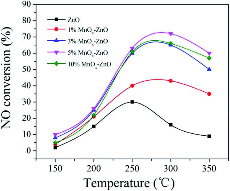 | ||
| Fig. 1 NO conversion as a function of temperatures over ZnO and MnOx–ZnO catalysts. | ||
| Catalyst | Calcination time | Reaction temperature (°C) | NO conversion (%) | Ref. |
|---|---|---|---|---|
| 5% MnOx–ZnO | 600 °C for 2 h | 275 | 72.1 | This work |
| 5% MnOx–ZnO | 600 °C for 4 h | 275 | 75.5 | This work |
| 5% MnOx–ZnO | 600 °C for 6 h | 275 | 75.1 | This work |
| MA-MnOx/TiO2 | 600 °C in N2 | 380 | 53.2 | 24 |
| MA-MnOx/TiO2 | 600 °C in O2 | 380 | 40.7 | 24 |
| MA-MnOx/TiO2 | 600 °C in air | 380 | 29.1 | 24 |
| Mn3O4 | 400 °C for 1 h | 275 | 70.3% | 25 |
3.2. Physical and texture characterizations
The thermogravimetric curve of MOF-5 is illustrated in Fig. 2. It can be seen that the apparent loss of three weights. Between 50 and 100 °C, there is about 4% continuous weight loss resulting from moisture evaporation from the sample surface. Secondly, the evaporation and decomposition of residual organic components (DMF) happened between 150–320 °C.26 The most significant weight loss occurred at temperatures above 420 °C, and the weight loss reached nearly 60% at an extremely fast rate, indicating that the skeleton of the MOF-5 has collapsed. Based on previous studies, for MOF-5, the break of the carboxyl bridge between the benzene ring and the Zn4O cluster causes the organic ligand molecule to decompose into CO2 and benzene,11 and the material has been decomposed into the crystal ZnO. After 550 °C, the decomposition process is completed. Thermal weight analysis evidence proves that MOF-5 crystals can be completely converted to ZnO above 550 °C. Hence, 600 °C was determined as the calcination temperature.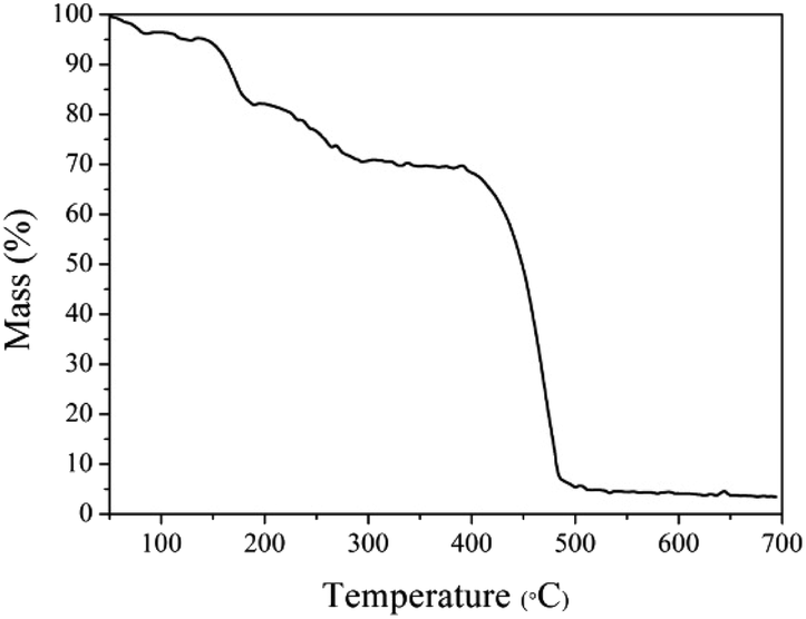 | ||
| Fig. 2 The TG profile for the MOF-5 precursor. | ||
According to the XRD diagram, we can confirm the transformation. Fig. 3(a) shows the representative diffraction peaks of MOF-5 material, of which 6.85°, 9.62°, 13.69°, 15.39° consistent with (200), (220), (400) and (420) planes.11 The high crystallinity of MOF-5 material can be identified by the sharp peak at 6.85°.11 In the meantime, from Fig. 3(b) we found that the initial framework structure collapsed in MOF-5 derived composites, the reflections locating at 31.7°(100), 34.4°(002), 36.3°(101), 47.4°(102), 56.6°(110), 62.8°(103), 67.9°(112) and 69.1°(201) were indexed to the characteristic peaks of wurtzite ZnO structure (JCPDS No. 36-1451).26 Furthermore, no peaks of MnOx phases were detected over 1% MnOx–ZnO, 3% MnOx–ZnO and 5% MnOx–ZnO catalysts, which indicated that MnOx species were highly dispersed over MOF-5 support or incorporated into MOF-5 lattice to form solid solution.27 However, 10% MnOx–ZnO sample displayed an additional XRD peak corresponded to the Mn3O4, indicating agglomeration of excess Mn compounds.
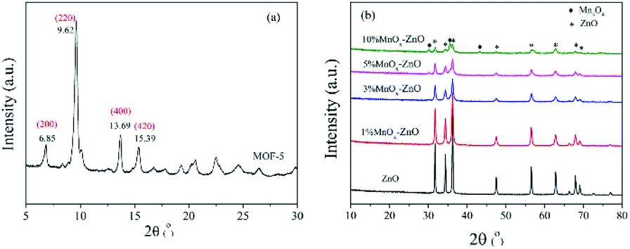 | ||
| Fig. 3 XRD pattern of (a) MOF-5 and (b) ZnO and MnOx–ZnO. | ||
The FTIR spectra of the ZnO and MnOx–ZnO catalysts derived from the MOF-5 were shown in Fig. 4. They show strong absorption peaks near 430 cm−1, which is a sign of lattice vibrations of the Zn–O bond in ZnO.28 In addition, the absorption peak of 1620 cm−1 is attributed to the OH bond bending vibration. The study of the absorption peak shows that the addition of Mn causes its ions to exist in the structure of MnOx–ZnO cooperates with the carboxyl group, which will enhance the potential of the adsorption site. The interaction between these adsorption sites and the gas molecules to be adsorbed is further enhanced and the adsorption amount is increased. With the increase of the Mn content, the larger shift in the absorption peak at 614 cm−1 may be ascribed to the doping of Mn.
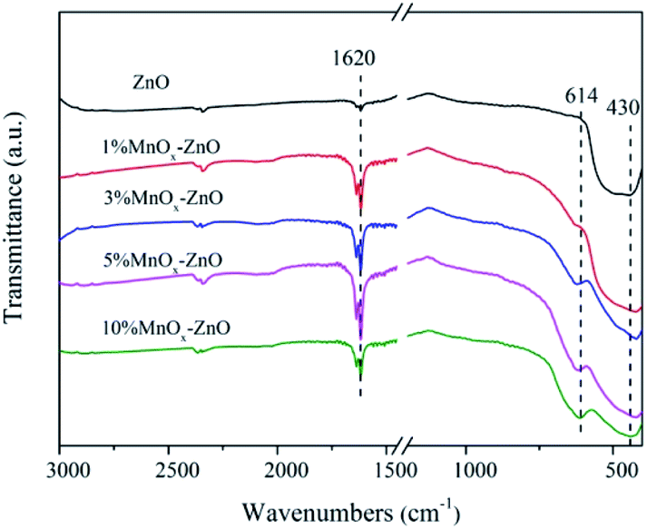 | ||
| Fig. 4 FT-IR spectra of ZnO and MnOx–ZnO catalysts. | ||
The scanning electron microscope photos of the catalysts are shown in Fig. 5. The MOF-5 sample clearly showed a cubic crystal shape with a smooth small surface, accompanied by a particle size range of 200 nm to 500 nm (Fig. 5(a)). Upon heating to 600 °C, the oxides (ZnO, MnOx–ZnO) maintain a cubic structure, whereas the edges become smooth and the surface appears porous (Fig. 5(b) and (c)). Moreover, the particle size of the ZnO and MnOx–ZnO catalysts decreased slightly compared to that of the MOF-5. As expected, when the MOF-5 and Mn/MOF-5 are heated, they gradually decompose over time, leading to smaller, porous and cubic particles.
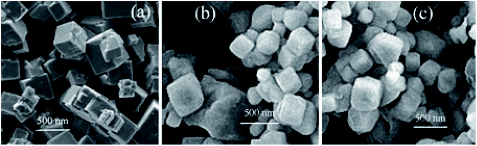 | ||
| Fig. 5 SEM images of (a) MOF-5, (b) ZnO and (c) MnOx–ZnO. | ||
The XPS spectra of Mn 2p3/2 are illustrated in Fig. 6(a). After a peak fitting deconvolution, the signal of Mn2+ (640.2 eV) and Mn4+ (645.5 eV) can be discovered. Previous literature reported that the redox process of Mn4+ species of vital importance in selective catalytic reaction with NH3 at low-temperature (NH3-SCR).29 High Mn4+ concentration can promote the oxidation of NO to NO2, thereby helping the NH3-SCR processes through the “rapid SCR” approach.
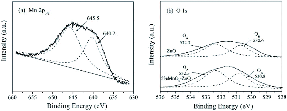 | ||
| Fig. 6 XPS spectra for (a) Mn 2p3/2 of the 5% MnOx–ZnO sample, (b) O 1s of the ZnO and 5% MnOx–ZnO samples. | ||
Fig. 6(b) displayed the O 1s XPS spectra of ZnO and 5% MnOx–ZnO samples, which were fitted into two different peaks representing surface lattice oxygen (O2−) (530 eV, denoted as OA) and surface chemisorbed oxygen or surface hydroxyl species (532.0 eV, denoted as OB).30,31 It is said that O2− is the most active oxygen species and important for NO oxidation.31 As shown in Fig. 6(b), for the 5% MnOx–ZnO catalyst, its total superficial O surface concentration, especially OA concentration is more than that of ZnO sample, which will promote the oxidation of NO to NO2.
The H2-TPR technology was employed in evaluating the reducibility of the catalysts. For all samples (Fig. 6), there are one obvious peak centered at 620 °C. With the increase of manganese content, the redox performance of the MnOx–ZnO catalysts have a clear transition to low temperatures, indicating that the redox performance of the catalysts is improved due to the interaction of ZnO and MnOx. Moreover, two new H2 desorption peaks could be observed over all MnOx–ZnO catalysts. The first reduction peak at about 450 °C is due to the reduction of Mn2O3 to Mn3O4,29 and the second reduction peak at 550 °C is attributed to the reduction of Mn3O4 to MnO.29 The results reveal that the reduction performance of MnOx–ZnO catalyst is stronger than that of ZnO. Following the enhanced redox performance could promote more NO being transferred and oxidated into NO2 (Fig. 7).
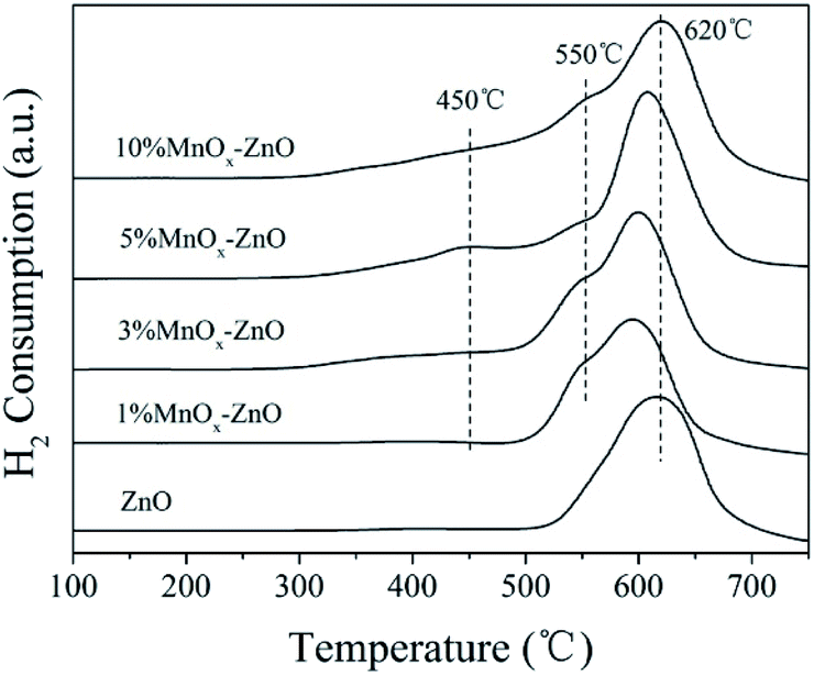 | ||
| Fig. 7 H2-TPR spectra of ZnO and MnOx–ZnO catalysts. | ||
3.3. NO-TPD measurements
To address the adsorption process, TPD-mass spectroscopy (MS) measurement were obtained. Fig. 8 shows the NO-TPD experiments for as-prepared catalysts. There are overlapped NO desorption peaks for all the samples, showing several NO adsorption species. The lower NO desorption temperatures between 176 and 208 °C could be attributed to physically adsorbed NO, whereas the higher desorption peaks recorded between 219 and 260 °C could be assigned to strongly adsorbed NO and chemically adsorbed species (nitrate or nitrite).32 Obviously, after Mn was added to the catalysts, the desorption peaks moved to a higher temperature, indicating that Mn can greatly enhance the bonding between NO and the catalyst surface. In addition, the desorption peak area of the manganese containing catalysts are significantly larger than that of the MOF-5 derived ZnO (Table 2), which indicates that the addition of Mn changes the chemical state of the catalyst surface, redistribution of adsorbed NOx, thereby promoting the oxidation of NO. It is worth noting that after the Mn content reaches more than 10%, the promotion effect increases very slowly. This may be caused by excessive Mn agglomeration. On the whole, Mn doping could promote high dispersion of active species and further accelerate NO adsorptive and oxidative reaction. The results are well consistent with the data for catalytic test (Fig. 1).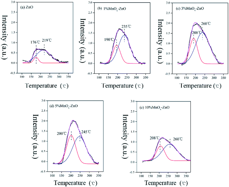 | ||
| Fig. 8 NO-TPD profiles of ZnO and MnOx–ZnO catalysts. | ||
| Sample | Physical desorption peak area (a.u.) | Chemical desorption peak area (a.u.) | Total desorption peak area (a.u.) |
|---|---|---|---|
| ZnO | 58.1 | — | 58.1 |
| 1% MnOx–ZnO | 45.0 | 109.2 | 154.2 |
| 3% MnOx–ZnO | 64.9 | 145.0 | 209.9 |
| 5% MnOx–ZnO | 110.1 | 156.3 | 266.3 |
| 10% MnOx–ZnO | 42.2 | 87.2 | 129.4 |
3.4. Py-FTIR
Pyridine is one of the most widely used basic probe molecules to evaluate the nature and numbers of acidic centers. The FTIR spectra of pyridine chemisorbed on the ZnO and 5% MnOx–ZnO catalysts evacuated at 250 °C are presented in Fig. 9. The catalysts displayed absorption peaks at wave numbers at 1464 and 1479 cm−1, corresponding to the pyridine coordinated on Lewis acid sites.30 The band at 1546 cm−1 was assigned to pyridinium cations formed after pyridine adsorption on Brønsted acid sites. Compared with ZnO catalyst, introduction of Mn led to the formation of Brønsted acid sites. Previous studies proposed that Brønsted acid sites favor NO reduction and are important SCR active sites as they can provide a reservoir of the reductant in the vicinity of the reduction site.33 Therefore, the ZnO catalyst exhibited relatively weak NO adsorption strength and NO reduction ability, which agreed with the results of the catalytic test and NO-TPD results.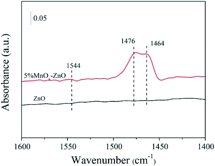 | ||
| Fig. 9 In situ FTIR spectra of pyridine adsorbed on ZnO and 5% MnOx–ZnO catalysts. | ||
3.5. In situ FTIR studies
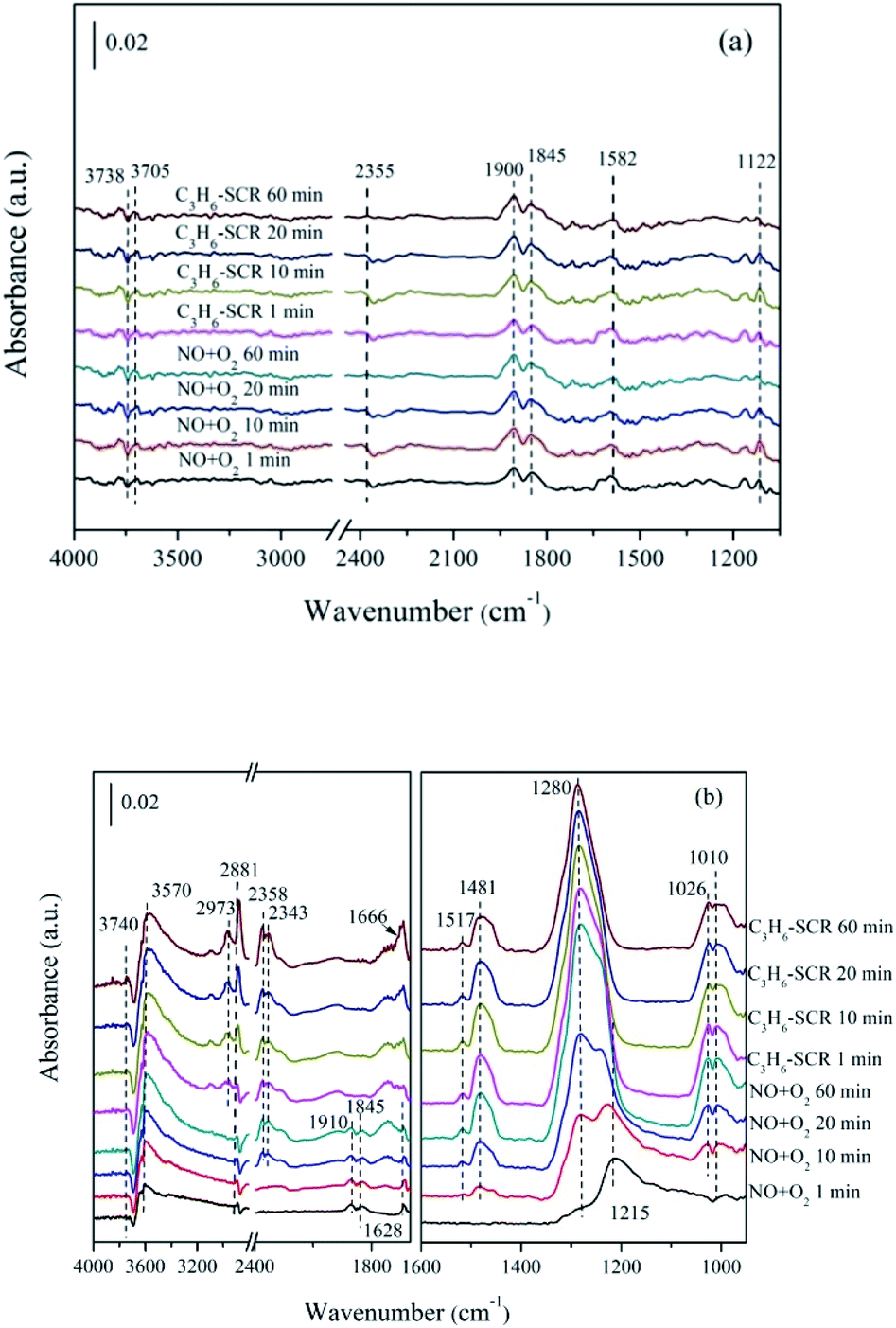 | ||
| Fig. 10 In situ FTIR of (a) ZnO, (b) 5% MnOx–ZnO exposed to the SCR reaction at 250 °C for various times under NO/O2 adsorption and during C3H6 interaction with the NO/O2 gas mixture. | ||
As for 5% MnOx–ZnO catalyst (Fig. 10(b)), monodentate nitrate (1010, 1026 and 1280 cm−1), bidentate nitrate (1481 and 1517 cm−1), bridge bidentate nitrate (1215 cm−1), nitrosyl (at 1845 and 1910 cm−1) and gas-phase NO (1628 cm−1) species were formed after flushed by NO/O2 for 10 min, indicating 5% MnOx–ZnO exhibited better adsorption performance compared to MOF-5 derived ZnO sample. Introduction of C3H6/O2 led to bridge bidentate nitrate (1215 cm−1) and nitrosyl (1845 cm−1and 1910 cm−1) disappearance, and also resulted in part monodentate nitrate species decreasing (1010 cm−1). In addition, there was no significant change in bidentate nitrates (at 1481 and 1517 cm−1). The absorption peak of the bridged bidentate nitrate (1215 cm−1) gradually increases to the maximum after 10 min, and then it was decreasing with the appearance and enhancement of the monodentate nitrate (1280 cm−1). The results show that monodentate nitrate is converted from partially bridged bidentate nitrate.
Switching to C3H6/O2 mixture, several new bands centered at 2973 and 2881 cm−1 were due to the asymmetric (νas) and symmetric (νsym) C–H stretching mode of CH3 group, which had reported by Efstathiou' group to present –CH3 group produced from the interplay between C3H6 and the catalyst surface.38 Furthermore, the new band recorded at the 1660 cm−1 is correspond to the enolic species (RCH![[double bond, length as m-dash]](https://www.rsc.org/images/entities/char_e001.gif) CH–O–).38 Besides, the bands with high intensity at 2343 cm−1 and 2358 cm−1 generated after C3H6 admission were attributed to gas phase CO2. The band at 3570 cm−1 was due to the ν(OH) stretching of adsorbed H2O.30 The band at 3740 cm−1 was attributed to the vibrational modes of the surface hydroxyl species (OH).39 It can be seen that the intensities of these bands increase significantly over time, which means that considerable amounts of CO2 and H2O are produced during the C3H6-SCR reaction. Actually, the increase of the –CHx was seemed controlled by the rate of propene dissociative chemisorption. According to the previous works,35 the interplay between adsorbed NO and –CHx adsorbed species produced from C3H6 are key steps of C3H6-SCR. They reacted with each other and gave rise to CO2, N2 and H2O.
CH–O–).38 Besides, the bands with high intensity at 2343 cm−1 and 2358 cm−1 generated after C3H6 admission were attributed to gas phase CO2. The band at 3570 cm−1 was due to the ν(OH) stretching of adsorbed H2O.30 The band at 3740 cm−1 was attributed to the vibrational modes of the surface hydroxyl species (OH).39 It can be seen that the intensities of these bands increase significantly over time, which means that considerable amounts of CO2 and H2O are produced during the C3H6-SCR reaction. Actually, the increase of the –CHx was seemed controlled by the rate of propene dissociative chemisorption. According to the previous works,35 the interplay between adsorbed NO and –CHx adsorbed species produced from C3H6 are key steps of C3H6-SCR. They reacted with each other and gave rise to CO2, N2 and H2O.
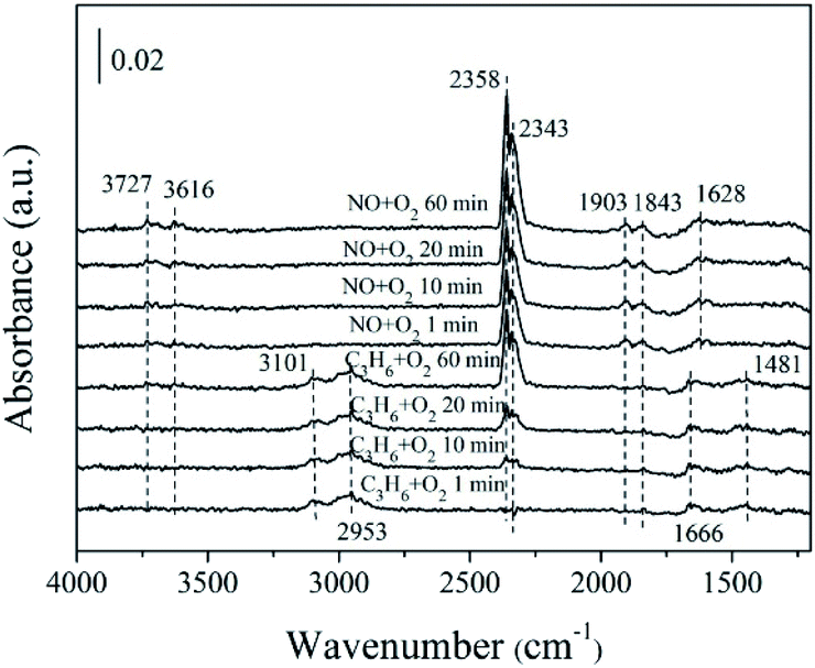 | ||
| Fig. 11 In situ FTIR of 5% MnOx–ZnO exposed to the SCR reaction at 250 °C for various times under C3H6/O2 adsorption and during NO/O2 interaction with the C3H6/O2 gas mixture. | ||
Previous study38 has investigated that species produced by C3H6 adsorption on oxidic surfaces would further react with oxygen, which results in partial oxidation and formation of acrolein. Subsequently, acrolein is ulteriorly oxidized into –CHx from the acrylate (CxHyOz) intermediate which is formed at the beginning. Our DRIFTS spectra results (Fig. 11) are in harmony with the above theory. The number of surface chemisorbed –CHx species is decreased by reacting with NO though hydrocarbonate species tend to decompose directly to CO2, N2 and H2O.
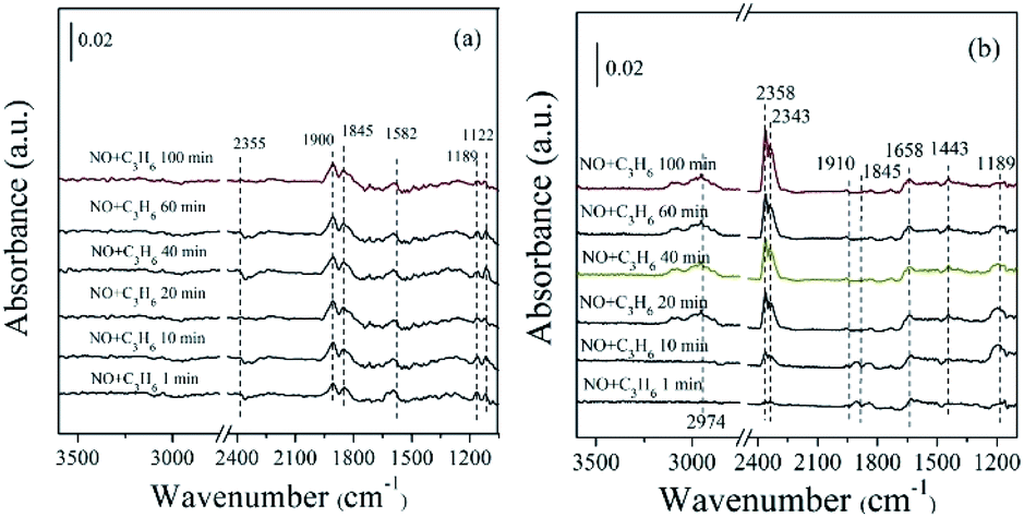 | ||
| Fig. 12 In situ FTIR of (a) ZnO, (b) 5% MnOx–ZnO exposed to the SCR reaction at 250 °C for various times under 1000 ppm NO + 1000 ppm C3H6. | ||
In the case of 5% MnOx–ZnO catalyst (Fig. 12(b)), there are more plenty and kinds surface intermediates. The main species are bidentate nitrate (1443 cm−1), bridge bidentate nitrate (1189 cm−1), nitrosyl (1845 and 1900 cm−1), enolic species (1658 cm−1) and gas phase CO2 (2358 and 2343 cm−1). By comparing the adsorption amount of intermediate species, it can be concluded that the introduction of Mn promotes the adsorptive and active ability of catalyst for NO and C3H6.
3.6. Reaction pathway
The reaction mechanism can reveal the catalytic process and provide guidance for the improvement of catalyst performance.39–42 Specifically, the proper introduction of manganese significantly boosts the catalytic performance. The reaction mechanism of the HC-SCR over MOF-5 derived MnOx–ZnO catalysts conforms to the “reduction” mechanism scheme. It can be understood through analysis of XPS, H2-TPR, NO-TPD and in situ FTIR. First, NO was adsorbed and subsequently oxidized with O2 to NO2 and stored in the form of bridged bidentate nitrates, nitrosyls, monodentate nitrates and bidentate nitrates at the Mn species or Zn2+ active sites. At the same time, a large number of CxHyOz (enolic species and acrylate) are formed and activated at these Mn species or Zn2+ active sites. Afterwards, the two kinds of intermediates above are active in the interaction with each other towards oxidation production (N2, CO2 and H2O) via generation of hydrocarbonate or carbonate species. Combining with our present work, it is demonstrated that addition of Mn improves the formation of adsorbed NOx substances and contributes to the improvement of C3H6-SCR activity due to increasing plenty of available active sites.4. Conclusions
It is easy to synthesize MOF-based derivative x% MnOx–ZnO (x = 1, 3, 5, 10) catalysts though thermal decomposition of Mn/MOF-5 precursor. The series of MnOx–ZnO (x = 1, 3, 5, 10) catalysts are obtained upon calcination form the Mn/MOF-5 precursor. The physical and chemical properties of these catalysts were systematically studied with a series of comprehensive characterization. It is concluded that as-prepared MnOx–ZnO can accelerate the interaction between Mn species (Mn2+ or Mn3+) and Zn2+. It was found that doping of manganese significantly improved the catalytic activity over catalysts. The 5% MnOx–ZnO exhibits the highest NO conversion of 75.5% under C3H6-SCR. In situ FTIR and NO-TPD analysis showed that monodentate nitrates, bidentate nitrates, bridged bidentate nitrates, nitrosyl groups and CxHyOz species were formed on the surface, and further hydrocarbonate or carbonates were formed as intermediates.Conflicts of interest
There are no conflicts to declare.Acknowledgements
This study is supported by National Natural Science Foundation of China (No. 21866022, 21567018, 21347001), Inner Mongolia Natural Science Foundation (2017MS0214), Inner Mongolia Engineering Research Center of Coal Chemical Wastewater Treatment & Resourcelization.References
- Y. Mathieu, L. Tzanis, M. Soulard, J. Patarin, M. Vierling and M. Molière, Fuel Process. Technol., 2013, 114, 81–100 CrossRef
.
- J. N. Wang, Y. Lei, J. T. Yang and G. Yan, Environ. Sci. Technol., 2012, 46, 4263–4264 CrossRef PubMed
- N. A. S. Amin, E. F. Tan and Z. A. Manan, J. Catal., 2004, 222, 100–106 CrossRef
- X. Y. Liu, Z. Jiang, M. X. Chen, J. W. Shi, Z. X. Zhang and W. F. Shangguan, Ind. Eng. Chem. Res., 2011, 50, 7866–7873 CrossRef
- H. A. Habib, R. Basner, R. Brandenburg, U. Armbruster and A. Martin, ACS Catal., 2014, 2479–2491 CrossRef
- H. Pan, Y. H. Guo, Y. F. Jian and C. He, Energy Fuels, 2015, 29, 5282–5289 CrossRef
- G. Y. Xu, Y. B. Yu and H. He, ACS Catal., 2018, 8, 2699–2708 CrossRef
- Y. H. Hu and K. Griffiths, Appl. Surf. Sci., 2008, 254, 5048–5054 CrossRef
- K. Köhler and C. H. He, J. Phys. Chem. C, 2011, 115, 1248–1254 CrossRef
- H. X. Jiang, Q. Y. Wang, H. Q. Wang, Y. F. Chen and M. H. Zhang, ACS Appl. Mater. Interfaces, 2016, 8, 26817–26826 CrossRef PubMed
- L. Zhang and Y. H. Hu, Mater. Sci. Eng., B, 2011, 176, 573–578 CrossRef
- W. Y. Huang, X. Zhou, Q. B. Xia, J. H. Peng, H. H. Wang and Z. Li, Ind. Eng. Chem. Res., 2014, 53, 11176–11184 CrossRef
- Z. J. Li, Y. L. Xiao, W. J. Xue, Q. Y. Yang and C. L. Zhong, J. Phys. Chem. C, 2015, 119, 3674–3683 CrossRef
- Q. Naddaf, M. Mansour, H. Thakkar and F. Rezaei, Ind. Eng. Chem. Res., 2018, 57, 17470–17479 CrossRef
- L. Zhang, L. Huang, Y. H. Qin and B. Z. Chen, Trans. Nonferrous Met. Soc. China, 2018, 28, 980–988 CrossRef CAS
- X. Chen, X. Chen, E. Q. Yu, S. C. Cai, H. P. Jia, J. Chen and P. Liang, Chem. Eng. J., 2018, 344, 469–479 CrossRef CAS
- K. Cendrowski, P. Skumial, P. Spera and E. Mijowska, Mater. Des., 2016, 110, 740–748 CrossRef CAS
- A. Pariyar, H. Y. Asl and A. Choudhury, Inorg. Chem., 2016, 55, 9250–9257 CrossRef CAS
- L. Wang, Y. Wu, R. Cao, L. Ren, M. Chen, X. Feng, J. Zhou and B. Wang, ACS Appl. Mater. Interfaces, 2016, 8, 16736–16743 CrossRef CAS PubMed
- H. Li, W. Shi, K. Zhao, H. Li, Y. Bing and P. Cheng, Inorg. Chem., 2012, 51, 9200–9207 CrossRef CAS PubMed
- S. C. Deng, T. T. Meng, B. L. Xu, F. Gao, Y. H. Ding, L. Yu and Y. N. Fan, ACS Catal., 2016, 6, 5807–5815 CrossRef CAS
- M. Kang, E. D. Park, J. M. Kim and J. E. Yie, Appl. Catal., 2007, 327, 261–269 CrossRef CAS
- L. J. Yan, Y. Y. Liu, K. W. Zha, H. R. Li, L. Y. Shi and D. S. Zhang, ACS Appl. Mater. Interfaces, 2017, 9, 2581–2593 CrossRef CAS
- J. L. Xie, D. Fang, F. He, J. F. Chen, Z. B. Fu and X. L. Chen, Catal. Commun., 2012, 28, 77–81 CrossRef CAS
- S. Andreoli, F. A. Deorsola, C. Galletti and R. Pirone, Chem. Eng. J., 2015, 278, 174–182 CrossRef CAS
- A. V. Rajgure, N. L. Tarwal, J. Y. Patil, L. P. Chikhale, R. C. Pawar, C. S. Lee, I. S. Mulla and S. S. Suryavanshi, Ceram. Int., 2014, 40, 5837–5842 CrossRef CAS
- X. H. Li, S. L. Zhang, Y. Jia, X. X. Liu and Q. Zhong, J. Nat. Gas Chem., 2012, 21, 17–24 CrossRef CAS
- R. Sabouni, H. Kazemian and S. Rohani, Chem. Eng. J., 2010, 165, 966–973 CrossRef CAS
- D. Fang, J. L. Xie, H. Hu, H. Yang, F. He and Z. B. Fu, Chem. Eng. J., 2015, 271, 23–30 CrossRef CAS
- L. Zhao, X. Y. Li, X. Quan and G. H. Chen, Environ. Sci. Technol., 2011, 45, 5373–5379 CrossRef CAS PubMed
- F. Liu, H. He and Y. Ding, Appl. Catal., B, 2009, 93, 194–204 CrossRef CAS
- H. Teng, L. Hsu and Y. Lai, Environ. Sci. Technol., 2001, 35, 2369–2374 CrossRef CAS PubMed
- J. Liu, X. Y. Li, Q. D. Zhao, C. Hao and D. K. Zhang, Environ. Sci. Technol., 2013, 47, 4528–4535 CrossRef CAS PubMed
- K. Ueda, J. Y. Ohyama and A. Satsuma, ACS Omega, 2017, 2, 3135–3143 CrossRef CAS PubMed
- W. Yang, R. D. Zhang, B. H. Chen, D. Duprez and S. Royer, Environ. Sci. Technol., 2012, 46, 11280–11288 CrossRef CAS
- J. Liu, X. Y. Li, Q. D. Zhao, C. Hao, S. B. Wang and M. Tade, ACS Catal., 2014, 4, 2426–2436 CrossRef CAS
- X. X. Cheng, Y. R. Cheng, Z. Q. Wang and C. Y. Ma, Fuel, 2018, 214, 230–241 CrossRef CAS
- C. M. Kalamaras, G. G. Olympiou, V. I. Pârvulescu, B. Cojocaru and A. M. Efstathiou, Appl. Catal., B, 2017, 206, 308–318 CrossRef CAS
- J. L. Long, Z. Z. Zhang, Z. X. Ding, R. S. Ruan, Z. H. Li and X. X. Wang, J. Phys. Chem. C, 2010, 114, 15713–15727 CrossRef CAS
- M. Haneda, N. Bion, M. Daturi, J. Saussey, J. C. Lavalley, D. Duprez and H. Hamada, J. Catal., 2002, 206, 114–124 CrossRef CAS
- R. Burch, J. P. Breen and F. C. Meunier, Appl. Catal., B, 2002, 39, 283–303 CrossRef CAS
- H. Hu, K. W. Zha, H. R. Li, L. Y. Shi and D. S. Zhang, Appl. Surf. Sci., 2016, 387, 921–928 CrossRef CAS
Footnote |
| † Electronic supplementary information (ESI) available. See DOI: 10.1039/d0ra04161k |
| This journal is © The Royal Society of Chemistry 2020 |