DOI:
10.1039/D0RA04129G
(Paper)
RSC Adv., 2020,
10, 24493-24506
Catalytic oxidation of NO over MnOx–CoOx/TiO2 in the presence of a low ratio of O3/NO: activity and mechanism†
Received
8th May 2020
, Accepted 16th June 2020
First published on 2nd July 2020
Abstract
In order to broaden the temperature range of NO oxidation reaction in flue gas and maintain high oxidation efficiency, various loading amounts of MnOx–CoOx/TiO2 mesoporous catalysts were tested in the catalytic oxidation of NO. It was found that 15%MnOx–CoOx(2![[thin space (1/6-em)]](https://www.rsc.org/images/entities/char_2009.gif) :1)/TiO2 demonstrated the best adsorption performance to oxygen species and contained more oxygen vacancies, as well as the best surface oxygen mobility, thus exhibiting excellent NO catalytic oxidation activity. O3 (O3/NO < 1) combined with 15%MnOx–CoOx(2:1)/TiO2 improved the oxidation efficiency of NO at 50–400 °C, especially below 250 °C. When the temperatures were less than 250 °C, the oxidation efficiencies of NO by O3 over 15%MnOx–CoOx(2:1)/TiO2 were 5–13% higher than the calculated theoretical efficiencies. This indicated that there was a synergistic effect between O3 and 15%MnOx–CoOx(2:1)/TiO2 below 250 °C. Based on the results of in situ DRIFTS studies, it was deduced that monodentate nitrates were the main intermediates that produced a synergistic effect due to the introduction of O3. In addition, O3 accelerated the transformation between nitrate species, decreased the decomposition temperature of nitrate species, and inhibited the accumulation of nitrate ions, thus improving the oxidation efficiency of NO.
:1)/TiO2 demonstrated the best adsorption performance to oxygen species and contained more oxygen vacancies, as well as the best surface oxygen mobility, thus exhibiting excellent NO catalytic oxidation activity. O3 (O3/NO < 1) combined with 15%MnOx–CoOx(2:1)/TiO2 improved the oxidation efficiency of NO at 50–400 °C, especially below 250 °C. When the temperatures were less than 250 °C, the oxidation efficiencies of NO by O3 over 15%MnOx–CoOx(2:1)/TiO2 were 5–13% higher than the calculated theoretical efficiencies. This indicated that there was a synergistic effect between O3 and 15%MnOx–CoOx(2:1)/TiO2 below 250 °C. Based on the results of in situ DRIFTS studies, it was deduced that monodentate nitrates were the main intermediates that produced a synergistic effect due to the introduction of O3. In addition, O3 accelerated the transformation between nitrate species, decreased the decomposition temperature of nitrate species, and inhibited the accumulation of nitrate ions, thus improving the oxidation efficiency of NO.
1. Introduction
NOx (including NO and NO2) are major pollutants emitted from fossil fuel combustion. In the last two decades, there has been much concern on techniques to control NOx emission. Selective catalytic reduction and selective non-catalytic reduction are widely used in industry,1 but the problems of high reaction temperature requirement, NH3 escape in flue gas, and difficulty in removing low concentrations of NOx still exist.2–4 In recent years, the oxidation technology of NO to NO2 has received attention.5–8 In particular, the applications of transition metal oxides to catalytic oxidation of NO were studied.9–12 Among them, MnOx and CoOx have been reported to show good activity for NO catalytic oxidation. Qiu13 prepared Mn–Co/TiO2 catalysts with different loadings by wet impregnation method. Their results indicated that the efficiency of NO oxidation by O2 was the best using 10Mn–5Co/TiO2 (loading ratio of Mn was 10 wt% and Co was 5 wt%) at 300 °C. Li14 found that the interaction between Co and Mn promoting the generation of Mn2O3 improved the NO oxidation by O2 above 250 °C. Nevertheless, the catalytic oxidation of NO by catalysts combined with oxygen is inefficient when the temperature was below 150 °C. To obtain higher efficiency of NO oxidation at low temperature, ozone has been widely used considering the lower secondary pollutants.6,15 Jõgi16 reported the NO oxidation by ozone over TiO2 catalyst and Lin17 reported the NO oxidation by O3 combined with MnOx catalyst supported by spherical alumina. It is agreed in these papers that when the temperature was less than 200 °C and the molar ratio of O3/NO < 1, the catalysts had no promoting effect on NO oxidation by O3, and the oxidation efficiency of NO to NO2 was the same as that when ozone oxidized NO alone. When the ratio of O3/NO was greater than 1, the presence of catalysts could promote the deep oxidation of NO2 to N2O5 by O3 and reduce the consumption of ozone. However, higher O3/NOx could result in the leakage of ozone and the increase in capital cost. Therefore, NO oxidation by catalysts combined with low concentration of O3 has become a new research target. Han18 found that black-TiO2 catalyst could increase the removal rate of NO in ozonation system at 60 °C when O3/NO = 0.6. However, so far, there have been few reports about the NO catalytic oxidation mechanism with low molar ratios of O3 to NO.
In this study, MnOx–CoOx/TiO2 catalysts with different loadings were prepared with 2:1 molar ratio of Mn to Co. The performance of these catalysts was investigated in NO catalytic oxidation. The optimum catalyst was selected for the research of NO oxidation by low molar ratios of O3/NO (O3/NO < 1) at 50–400 °C. A series of characterization techniques, such as N2 adsorption, X-ray diffraction (XRD), thermogravimetric-differential scanning calorimetry (TG-DSC), H2-temperature program reduction (H2-TPR), O2-temperature program desorption (O2-TPD) and X-ray photoelectron spectroscopy (XPS), were used to identify the physicochemical characteristics of the catalysts. The technology of in situ DRIFTS was introduced to explore the promotion mechanism of NO oxidation by low concentration of O3 in presence of MnOx–CoOx/TiO2.
2. Materials and methods
2.1 Catalyst preparation
The catalysts were prepared by impregnation method. Specific amounts of manganese nitrate solution (50 wt%, analytical grade) and Co(NO3)2·6H2O crystals (99 wt%, analytical grade) were added into 100 mL deionized water and the mixture was stirred for 30 min. A certain amount of anatase TiO2 powder (commercial anatase titanium dioxide) was added into the solution and stirring was continued for 2 hours. Then, the mixture was heated in a thermostatic water bath at 80 °C until the water was fully evaporated. The catalyst precursors were dried at 110 °C for 12 hours, and then calcined under air atmosphere at 500 °C for 4 hours. The calcined catalysts were ground to 40–60 mesh size for the activity tests. For the as-prepared MnOx–CoOx supported catalysts, the molar ratio of Mn to Co was 2:1 and total loadings of Mn and Co to TiO2 were 7 wt%, 10 wt%, 15 wt% and 20 wt%. Accordingly, they were denoted as 7%MnOx–CoOx(2:1)/TiO2, 10%MnOx–CoOx(2:1)/TiO2, 15%MnOx–CoOx(2:1)/TiO2 and 20%MnOx–CoOx(2:1)/TiO2, respectively.
2.2 Catalyst characterization
The specific surface areas and pore size distributions were determined by N2 adsorption at liquid nitrogen temperature 77 K using a Micromeritics ASAP 2020 HD88 instrument. XRD patterns were recorded by a D8 FOCUS X-ray diffractometer (Bruker) with Cu Kα radiation operated at 40 kV and 40 mA. TGA curves were recorded on a TA-Q600 analyzer over the temperature range from 20 °C to 1000 °C at the rate of 10 °C min−1 under N2. H2-TPR, O2-TPD and NO-TPD were carried out on PCA-1200 chemical adsorption instrument with a thermal conductivity detector. For H2-TPR, samples were pretreated at 200 °C for 90 min in nitrogen atmosphere, then cooled down to room temperature. Catalysts were flushed in a flow of H2 (5%)/N2 and then heated to 900 °C at a rate of 10 °C min−1. The H2 consumption of the test samples were calculated by the H2 consumption of 50 mg of CuO under the same reaction conditions. For O2-TPD, catalysts were purged at room temperature for 30 min and then at 200 °C for 2 h in He atmosphere. Subsequently, O2 was adsorbed at 100 °C for 1 h. The adsorbed catalyst was blown by He for 30 min at 100 °C, and then raised to 900 °C in He atmosphere (30 mL min−1) at a rate of 10 °C min−1. The O2 desorption quantity of each sample was calculated by standard pulse peak calibration method. For NO-TPD, catalysts were purged at 300 °C for 1 h in He atmosphere and then cooled down to room temperature. Subsequently, NO was adsorbed at room temperature for 1 h. The adsorbed catalysts were blown by He for 1 h at room temperature, and then raised to 500 °C in He atmosphere (30 mL min−1) at a rate of 10 °C min−1 for desorption experiments. Desorption signals were detected by a thermal conductivity detector. XPS data were collected using a ThermoScientific Escalab 250Xi photoelectron spectrometer with a standard Al Kα source (hν = 1486.6 eV). All binding energies were referenced to the C 1s line at 284.8 eV.
2.3 Catalytic tests
Activity tests of catalysts were carried out at 50–400 °C in a fixed-bed reactor that was 0.8 cm in diameter and 20 cm in length; the experimental system is shown in Fig. S1.† The simulated flue gases included 500 ppm NO, 4% O2 and N2 as carrier. O3 was generated from O2-ozone generator (SK-CFG-10A, 1–10 g h−1, Sankang, Jinan, China), and was monitored by ozone detector (GM-6000-OEM, 0–200 g m−3, Anseros, Germany). The molar ratio of O3/NO was 0.1 to 0.9. The total gas flow rate was 400 mL min−1 with a gaseous hourly space velocity (GHSV) of 24000 h−1. The inlet and outlet NO concentrations were determined by flue gas analyzer (KM940, Kane, UK). The conversion efficiency of NO was calculated by eqn (1):| |
 | (1) |
where NOinlet and NOoutlet denote the inlet and outlet NO concentrations (ppm), respectively.
2.4 In situ DRIFTS
In situ diffuse reflectance infrared Fourier transform spectroscopy (DRIFTS) was performed using a Bruker Tensor II instrument and Harrick Scientific DRIFTS cell with ZnSe windows. The total gas flow rate was 200 mL min−1 containing 500 ppm NO, 250 ppm O3, 4% O2 and N2 as carrier. The samples were pretreated under N2 atmosphere in DRIFTS cell at 400 °C for 1 h, and then cooled down to the target temperature to collect the background spectra. The spectra of NOx desorption as a function of temperature (25–400 °C) were recorded. The simultaneous adsorption data of NO and O3 or NO and O2 on 15%MnOx–CoOx(2:1)/TiO2 as a function of time were recorded at 100 °C and 350 °C, respectively. Static reaction spectra without fed gases, after NO and O3 co-adsorbed on 15%MnOx–CoOx(2:1)/TiO2 at 100 °C, was also recorded.
3. Results and discussion
3.1 Catalyst characterization
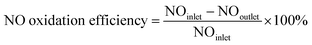
3.1.2 TG-DSC analysis. Fig. 2 shows the results of TG-DSC analysis. All the catalysts showed a significant weight loss at around 600 °C. Four decalescence points were observed on 15%MnOx–CoOx(2:1)/TiO2 from the DSC curves, but other catalysts had three. The decalescence points less than 100 °C indicated the evaporation of the remaining water in the catalysts. The wide decalescence valleys from 500 °C to 700 °C represented the transformation of MnO2 to Mn2O3, and the decalescence valleys from 700 °C to 850 °C represented the transformation of Mn2O3 to Mn3O4.19–21 In the DSC curve of 15%MnOx–CoOx(2:1)/TiO2 at 271 °C, there was a decalescence point and a weight-loss point, which indicated that Co2O3 hydrate was dehydrated to Co3O4.20 The continuous weight-loss from room temperature to approximately 600 °C confirmed that most of MnO2 probably existed in amorphous form and only a small amount of it might exist as crystallites.19
 |
| | Fig. 2 TG-DSC profiles of catalysts. | |
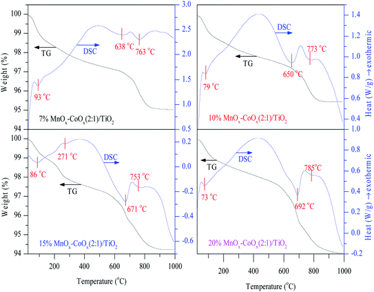
3.1.3 XRD analysis. XRD patterns were recorded to determine the crystal phases of the four catalysts and TiO2 carrier. As shown in Fig. 3, the distinct diffraction peaks of anatase TiO2 crystal (ICDD 01-089-4921) were detected on each catalyst and no characteristic peaks of CoOx were found. However, very weak characteristic peaks of Mn2O3 were detected on 15%MnOx–CoOx(2:1)/TiO2 and 20%MnOx–CoOx(2:1)/TiO2 with higher loading of Mn oxides, and no diffraction peaks of MnO2 were detected. Combined with the results of TG-DSC analysis, it could be speculated that the crystallinity of MnO2 on the catalyst was very low and might exist primarily in an amorphous form. Manganic oxide species and cobalt oxide species were well-dispersed on the surface of catalysts and/or had poor crystal structure,22 which would be beneficial to the catalytic reaction.23 Average grain sizes calculated by the most intense reflexion characterizing of anatase TiO2 using Scherrer formula are listed in Table 1. Decrease in average grain size of anatase TiO2 carrier with the increase in loading of MnOx–CoOx was probably due to that the increase in active components was not conducive to the agglomeration of the carrier crystal.
 |
| | Fig. 3 XRD patterns of catalysts. | |
3.1.6 NO-TPD analysis. The NO-TPD profiles of the four catalysts and TiO2 carrier are shown in Fig. 6. The desorption peaks of NO had two regions. The desorption peaks below 160 °C could be classified as weakly adsorbed species on the catalyst surface, such as physically adsorbed NO, monodentate nitrates and nitrites. The desorption peaks above 160 °C could be classified as bidentate nitrates and bridged nitrates, which had higher thermal stability.17,28 The desorption and decomposition of nitrates and nitrites will be discussed by in situ infrared spectroscopy via the thermal stability of nitrogen oxides adsorbed on the catalyst. Through NO-TPD profiles, it could be seen that with the increase in loading amount, the peak strength of NO desorption increased first and then decreased slightly, especially for the weakly adsorbed NO below 160 °C. The weakly adsorbed NO desorption peak on 15%MnOx–CoOx(2:1)/TiO2 was the largest when compared with other catalysts, indicating that 15%MnOx–CoOx(2:1)/TiO2 could adsorb more nitrate and nitrite species and participate in the oxidation reaction of NO, which is helpful to improve the oxidation efficiency of NO.
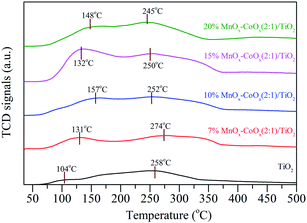 |
| | Fig. 6 NO-TPD profiles of catalysts. | |
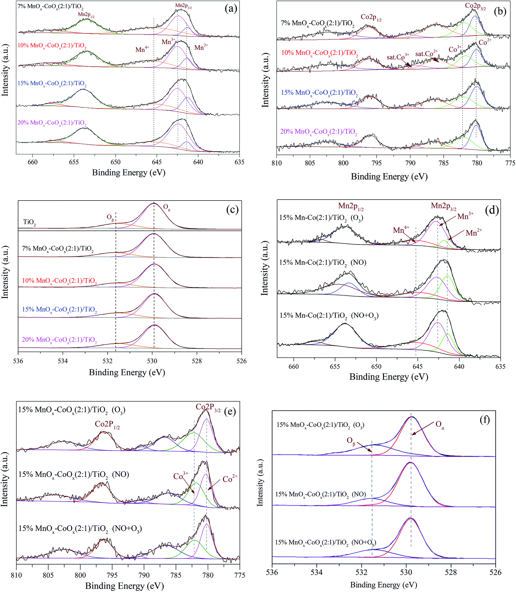
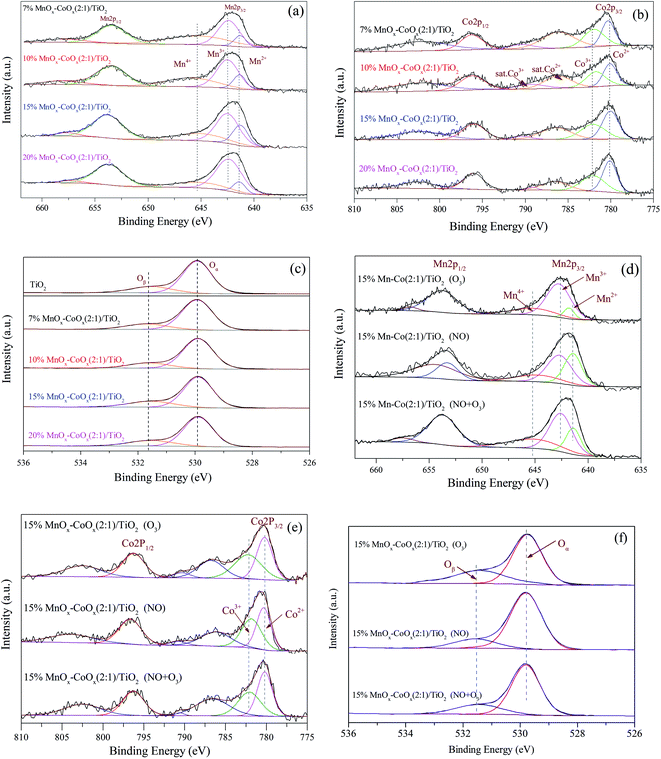
3.1.7 XPS analysis. The XPS spectra of Mn 2p, Co 2p and O 1s are shown in Fig. 7. In Fig. 7(a), the Mn 2p3/2 could be resolved into three sub-bands: Mn2+, Mn3+ and Mn4+.29,30 The binding energies (eV) and valence composition ratios (%) of Mn (Mnn+/Mn) are listed in Table 4. As the loading amount increased, Mn2+/Mn ratio increased first and then decreased; hence, 15%MnOx–CoOx(2:1)/TiO2 contained the highest Mn2+/Mn ratio. However, the Mn4+/Mn ratio decreased with the increase in loading while Mn3+/Mn increased. The presence of Mn3+ in manganese oxides could promote the formation of oxygen vacancies.31 The Co 2p in Fig. 7(b) had two main peaks at around 796.0 eV and 780.0 eV, belonging to Co 2p1/2 and Co 2p3/2, respectively. The satellite peaks at around 785.0–790.0 eV appeared representing the existence of Co2+.14 The binding energies of Co2+ and Co3+ are very close, which need to be judged by the split energy level difference of the spin orbits. ΔE(2p1/2 − 2p3/2) = 16.0 eV indicates that cobalt ions in the sample is mainly Co2+, while ΔE(2p1/2 − 2p3/2) = 15.0 eV indicates that cobalt ions in the sample is mainly Co3+.14,32 The binding energies (eV), ΔE(2p1/2 − 2p3/2) and valence composition ratios (%) of Co (Con+/Co) are listed in Table 5. ΔE(2p1/2 − 2p3/2) of the fresh catalysts were 15.72–15.88 eV, indicating that cobalt ions in these catalysts were mainly Co2+. Therefore, the peaks at around 780.27 eV could be classified as Co2+, and the peaks at around 782.12 eV could be classified as Co3+. As the loading amount increased, ΔE(2p1/2 − 2p3/2) decreased first and then increase. It meant that the content of Co3+ increased first and then decreased, which corresponded to the Co3+/Co ratio listed in Table 5. Co3+/Co was the highest in 15%MnOx–CoOx(2:1)/TiO2 among all the catalysts, while the opposite trend was observed for Co2+/Co. Fig. 7(c) shows the XPS spectra of O 1s. The corresponding binding energies (eV) and relative composition ratios (%) are listed in Table 6. The peaks at around 529.89 eV were assigned to lattice oxygen Oα,33 and the peaks at around 531.55 eV were assigned to oxygen species Oβ which were chemically adsorbed to oxygen vacancies.34 With the increase in loading of MnOx and CoOx, the relative composition ratios of Oα/O decreased first and then increased, while Oβ/O increased first and then declined. Consequently, Oβ/O was the highest in 15%MnOx–CoOx(2:1)/TiO2 among all the catalysts. This variation trend was consistent with the result of O2-TPD, which confirmed that 15%MnOx–CoOx(2:1)/TiO2 contained the largest amount of oxygen vacancies among the four catalysts, and was advantageous to adsorb oxygen species to be used in catalytic oxidation reaction.
 |
| | Fig. 7 XPS spectra of catalysts. (a) and (d) Mn 2p; (b) and (e) Co 2p; (c) and (f) O 1s. | |
Table 4 Mn 2p3/2 binding energies (eV) and valence composition (%)
| Catalyst |
Binding energies (eV) |
Valence composition ratios (%) |
| Mn 2p3/2 |
Mn2+ |
Mn3+ |
Mn4+ |
Mn2+/Mn |
Mn3+/Mn |
Mn4+/Mn |
| 7%MnOx–CoOx(2:1)/TiO2 |
642.08 |
641.41 |
642.48 |
645.34 |
10.54 |
44.25 |
45.21 |
| 10%MnOx–CoOx(2:1)/TiO2 |
642.08 |
641.42 |
642.50 |
645.36 |
15.18 |
50.13 |
34.69 |
| 15%MnOx–CoOx(2:1)/TiO2 |
642.07 |
641.40 |
642.50 |
645.32 |
17.11 |
53.39 |
29.50 |
| 20%MnOx–CoOx(2:1)/TiO2 |
642.07 |
641.42 |
642.49 |
645.32 |
9.56 |
67.07 |
23.37 |
| 15%MnOx–CoOx(2:1)/TiO2 (O3) |
642.09 |
641.44 |
642.53 |
645.30 |
10.71 |
55.72 |
33.57 |
| 15%MnOx–CoOx(2:1)/TiO2 (NO) |
642.07 |
641.40 |
642.55 |
645.28 |
42.27 |
46.26 |
11.47 |
| 15%MnOx–CoOx(2:1)/TiO2 (NO + O3) |
642.07 |
641.40 |
642.51 |
645.28 |
16.84 |
52.77 |
30.39 |
Table 5 Co 2p3/2 binding energies (eV) and valence composition (%)
| Catalyst |
Binding energies (eV) |
Valence composition ratios (%) |
| Co 2p3/2 |
ΔE(2p1/2 − 2p3/2) |
Co2+ |
Co3+ |
Co2+/Co |
Co3+/Co |
| 7%MnOx–CoOx(2:1)/TiO2 |
780.91 |
15.88 |
780.29 |
782.08 |
54.89 |
45.11 |
| 10%MnOx–CoOx(2:1)/TiO2 |
780.52 |
15.79 |
780.27 |
782.06 |
53.91 |
46.09 |
| 15%MnOx–CoOx(2:1)/TiO2 |
780.37 |
15.72 |
780.25 |
782.12 |
53.66 |
46.34 |
| 20%MnOx–CoOx(2:1)/TiO2 |
780.22 |
15.80 |
780.27 |
782.12 |
53.87 |
46.13 |
| 15%MnOx–CoOx(2:1)/TiO2 (O3) |
780.42 |
15.70 |
780.30 |
781.14 |
50.74 |
49.26 |
| 15%MnOx–CoOx(2:1)/TiO2 (NO) |
780.48 |
15.90 |
780.32 |
781.08 |
56.43 |
43.57 |
| 15%MnOx–CoOx(2:1)/TiO2 (NO + O3) |
780.34 |
15.80 |
780.27 |
782.10 |
54.52 |
45.48 |
Table 6 Oxygen species binding energies (eV) and relative composition (%)
| Catalyst |
Binding energies (eV) |
Relative composition ratios (%) |
| O 1s |
Oα |
Oβ |
Oα/O |
Oβ/O |
| TiO2 |
529.91 |
529.90 |
531.54 |
81.05 |
18.95 |
| 7%MnOx–CoOx(2:1)/TiO2 |
529.91 |
529.90 |
531.55 |
79.99 |
20.01 |
| 10%MnOx–CoOx(2:1)/TiO2 |
529.90 |
529.89 |
531.55 |
77.27 |
22.73 |
| 15%MnOx–CoOx(2:1)/TiO2 |
529.90 |
529.89 |
531.55 |
76.62 |
23.38 |
| 20%MnOx–CoOx(2:1)/TiO2 |
529.90 |
529.89 |
531.54 |
78.20 |
21.80 |
| 15%MnOx–CoOx(2:1)/TiO2 (O3) |
529.90 |
529.89 |
531.55 |
69.36 |
30.64 |
| 15%MnOx–CoOx(2:1)/TiO2 (NO) |
529.89 |
529.90 |
531.54 |
79.58 |
20.42 |
| 15%MnOx–CoOx(2:1)/TiO2 (NO + O3) |
529.90 |
529.89 |
531.55 |
75.73 |
24.27 |
The XPS spectra of the used 15%MnOx–CoOx(2:1)/TiO2 catalyst after the separate adsorption of O3 and NO, and the co-adsorption of O3 and NO at 100 °C are shown in Fig. 7(d)–(f). From Fig. 7(d) and Table 4, it showed that Mn2+/Mn on the surface of 15% Mn–Co(2:1)/TiO2 decreased significantly after O3 adsorption, while Mn3+/Mn and Mn4+/Mn on the surface of 15% Mn–Co(2:1)/TiO2 increased, which manifested that some of the manganese oxide were probably oxidized by O3 through eqn (2) and (3).17 While after NO adsorption, Mn3+/Mn and Mn4+/Mn on the surface of 15% Mn–Co(2:1)/TiO2 decreased, but Mn2+/Mn increased. This illustrated that NO adsorbed on the catalyst probably reacted with manganese oxide in high valence state through eqn (4) and (5).17 The changes in valence composition ratios of Mn2+/Mn, Mn3+/Mn and Mn4+/Mn on the surface of 15% Mn–Co(2:1)/TiO2 were not significant after NO and O3 co-adsorbed. It illustrated that the transformations among Mn2+, Mn3+ and Mn4+ in the NO catalytic oxidation process were almost in balance state. Similarly, Co3+/Co on the surface of 15% Mn–Co(2:1)/TiO2 increased while Co2+/Co decreased after O3 adsorption, in Fig. 7(e) and Table 5, which was probably due to the reaction of eqn (6). Co2+/Co increased while Co3+/Co decreased after NO adsorption, which was probably due to the reaction of eqn (7). Simultaneous adsorption of O3 and NO, the valence composition ratios of Co3+/Co and Co2+/Co were not changed obviously. It also illustrated that the transformations between Co3+ and Co2+ in the NO catalytic oxidation process were almost in balance state. The relative composition ratio of Oβ/O on the surface of 15%Mn–Co(2:1)/TiO2 (in Fig. 7(f) and Table 6) increased after O3 adsorption. Oβ/O decreased slightly after NO adsorption, which may be due to the consumption of chemisorption oxygen by NO reaction on the catalyst surface. After the co-adsorption of NO and O3, the change in relative composition ratio of Oβ/O was not obvious, illustrating that a balance state Oβ was set up during this process. It reflected that during the process of NO catalytic oxidation, reactive oxygen species decomposed from O3 could adsorb on the oxygen vacancies of catalyst, which could supplement the chemisorption oxygen consumed by NO oxidation.
| | |
O3 + [Mn2+] → O−[Mn3+] + O2
| (2) |
| | |
O3 + [Mn3+] → O−[Mn4+] + O2
| (3) |
| | |
O−[Mn4+] + NO–Mn → NO2–Mn + [Mn3+]
| (4) |
| | |
O−[Mn3+] + NO–Mn → NO2–Mn + [Mn2+]
| (5) |
| | |
O3 + [Co2+] → O−[Co3+] + O2
| (6) |
| | |
O−[Co3+] + NO–Co → NO2–Co + [Co2+]
| (7) |
3.2 NO oxidation properties
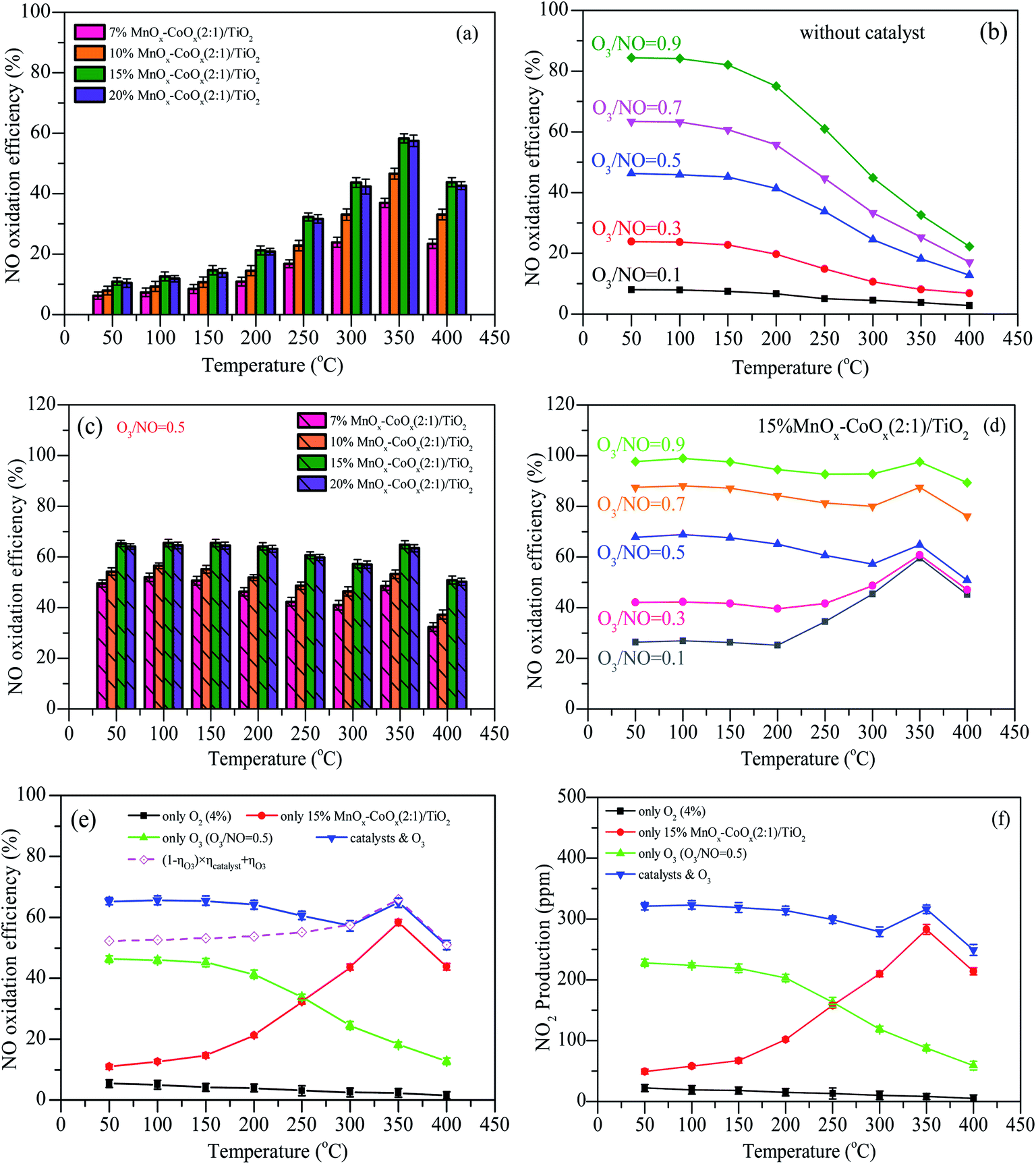
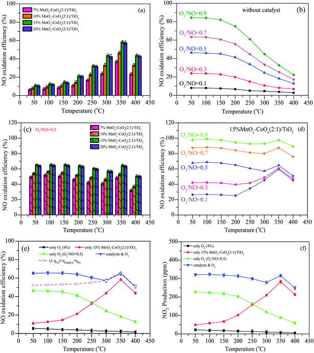
The results of NO oxidation efficiencies at different oxidation modes are shown in Fig. 8. With different loadings of MnOx–CoOx(2:1)/TiO2, NO oxidation efficiencies first increased with the increase in temperature, reaching the maximum value at 350 °C, and then decreased, as shown in Fig. 8(a). In the H2-TPR test, the low temperature reduction peak was around 332–350 °C, indicating that at the reaction temperature range of 50–400 °C, the active catalytic components were MnO2 and Co3O4. 15%MnOx–CoOx(2:1)/TiO2 exhibited the best catalytic efficiency, which can be owned to the best adsorption capacity of oxygen species by the results of O2-TPD and XPS. For NO oxidation only by O3, shown in Fig. 8(b), the efficiencies increased with the increase in O3/NO molar ratio, and decreased rapidly with the increase in temperature. Fig. 8(c) presents the NO oxidation efficiencies using varying loadings of MnOx–CoOx(2:1)/TiO2 combined with O3/NO = 0.5. With the increase in temperature, NO oxidation efficiencies increased first (50–100 °C), then decreased (100–300 °C) and again increased from 300 °C to 350 °C, after then decreased again (350–400 °C). Because of the excellent low temperature oxidation performance of ozone and high temperature activity of catalyst, the efficiencies of NO oxidation by ozone combined with catalyst showed this trend with the change in temperature. The introduction of O3 increased the NO oxidation efficiency, especially at low temperatures (<250 °C), when compared with NO catalytic oxidation by O2 in Fig. 8(a). This could be ascribed to the good desorption ability of adsorbed oxygen Oβ, as seen from the results of O2-TPD, and the good oxidation performance of O3 at low temperatures.
 |
| | Fig. 8 NO oxidation efficiencies at different oxidation modes. (a) Different loadings of MnOx–CoOx(2:1)/TiO2; (b) O3/NO; (c) different loadings of MnOx–CoOx(2:1)/TiO2 combined with O3/NO = 0.5; (d) 15%MnOx–CoOx(2:1)/TiO2 combined with O3; (e) comparison of NO oxidation by different modes; (f) NO2 yield by using different oxidation modes. Reaction conditions: flow = 400 mL min−1, NO = 500 ppm, O2 = 4%, GHSV = 24000 h−1. | |
N2 adsorption analysis showed that the specific surface area of the catalysts decreased with the increase in loading capacity. High specific surface area is helpful for the adsorption performance of the catalyst.22,35 However, as shown in Fig. 8(a) and (c), NO oxidation efficiencies increased with the total loading from 7% to 15%, which demonstrated that the loading amount or the content of active component was the main factor influencing the catalytic activity when compared to the specific surface area. The NO oxidation efficiency of 20%MnOx–CoOx(2:1)/TiO2 was slightly lower than that of 15%MnOx–CoOx(2:1)/TiO2. Although the highest content of Mn3+ was found in 20%MnOx–CoOx(2:1)/TiO2, which was favorable for the formation of oxygen vacancies due to the electrostatic balance,36 15%MnOx–CoOx(2:1)/TiO2 had the highest Co3+/Co and chemisorption oxygen Oβ in XPS analysis. It is likely that the interaction of manganese–cobalt produced the most oxygen vacancies at loading amount of 15 wt%, which could adsorb more oxygen species, thereby promoting NO catalytic oxidation.37,38 Therefore, NO catalytic oxidation efficiency of 15%MnOx–CoOx(2:1)/TiO2 was slightly higher than that of 20%MnOx–CoOx(2:1)/TiO2. Fig. 8(d) presents the efficiencies of NO oxidation by O3 (O3/NO = 0.1–0.9) over 15%MnOx–CoOx(2:1)/TiO2. Comparing Fig. 8(d) to Fig. 8(b), it was evident that NO oxidation efficiency was improved, especially in the high temperature region (250–400 °C). Therefore, the moderate concentration of O3/NO = 0.5 and 15%MnOx–CoOx(2:1)/TiO2 were selected as the experimental condition in the following analyses.
The comparisons of NO oxidation efficiencies by different modes are shown in Fig. 8(e) and (f) shows the production of NO2 by using different oxidation modes. In the experiment, the production of NO2 was almost corresponding to the oxidation efficiency of NO, indicating that NO2 was the main products when NO were oxidized by the methods of only using O2 (4%), only using 15%MnOx–CoOx(2:1)/TiO2 catalysts, only using O3 (O3/NO = 0.5), and using 15%MnOx–CoOx(2:1)/TiO2 combined with O3 (O3/NO = 0.5). In Fig. 8(e), without O3 and catalyst, the efficiencies of NO oxidation by O2 were lower than 5.4%, and decreased with the increase in temperature. This is because NO + O2 → NO2 is an exothermic reaction and its spontaneous reaction is inefficient at low concentration of O2.39 The oxidation efficiency of NO during oxidation by O3 was much higher than that during catalytic oxidation by O2 using 15%MnOx–CoOx(2:1)/TiO2 when the temperature was below 250 °C, whereas the catalytic reaction occurred more easily above 250 °C. The efficiencies of NO during catalytic oxidation by O3 using 15%MnOx–CoOx(2:1)/TiO2 were higher than that during either catalytic oxidation by O2 using 15%MnOx–CoOx(2:1)/TiO2 or oxidation by O3 only. According to the placement of the catalyst in the reactor (Fig. S1†), when NO and O3 were simultaneously fed into the fixed-bed reactor, NO was first oxidized by O3, and then the rest of NO was oxidized by O2 on the catalyst. The theoretical efficiency for combined oxidation was calculated using eqn (8):
| | |
(1 − ηO3) × ηcatalyst + ηO3
| (8) |
where, “
ηO3” refers to the NO oxidation efficiency by O
3 and “
ηcatalyst” represents the NO oxidation efficiency by O
2 using 15%MnO
x–CoO
x(2
:
1)/TiO
2.
It can be seen from Fig. 7(e) that the measured efficiencies of NO oxidation by O3 (O3/NO = 0.5) using 15%MnOx–CoOx(2:1)/TiO2 were 5–13% higher than the theoretical efficiencies calculated by eqn (8) below 250 °C, while the measured and theoretical efficiency values were very close above 300 °C. This result indicated that 15%MnOx–CoOx(2:1)/TiO2 and O3 exerted a synergistic effect on NO oxidation at temperatures below 250 °C, while the synergistic effect was not evident above 250 °C. The synergistic mechanism between 15%MnOx–CoOx(2:1)/TiO2 and O3 and its effect on NO oxidation will be discussed further in the later sections.
3.3 In situ DRIFTS studies
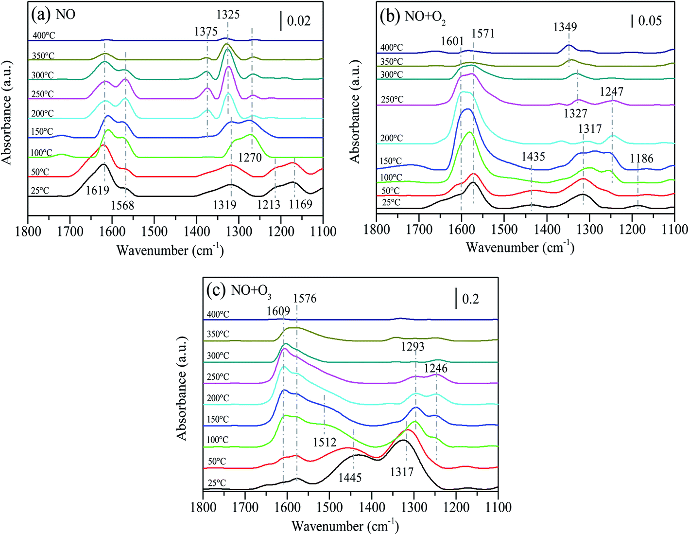
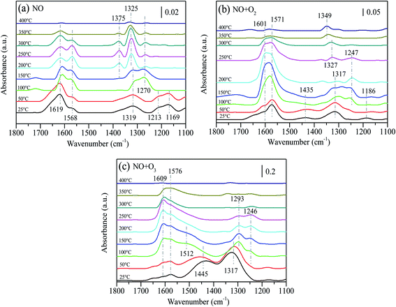
Fig. 9 presents the thermal stability of absorbed NOx species after 15%MnOx–CoOx(2:1)/TiO2 was exposed to different atmospheres. The fed gases were adsorbed on the catalyst surface at 25 °C for 30 min, then cut off the fed gases and conducted temperature desorption experiment. After NO adsorbed for 30 min at 25 °C, several peaks appeared at 1619 cm−1, 1568 cm−1, 1319 cm−1, 1213 cm−1 and 1169 cm−1 on the surface of 15%MnOx–CoOx(2:1)/TiO2, as shown in Fig. 9(a). The assignments of NOx species are listed in Table 7. As the temperature increased, the peak at 1619 cm−1 (bridging bidentate nitrates) gradually declined. The band at 1568 cm−1 (bidentate nitrates) increased first and then decreased from 250 °C until it disappeared at 350 °C. The bands at 1213 cm−1 and 1169 cm−1 (nitrites) vanished at 100 °C. The band at 1319 cm−1 (nitro–nitrito) gradually increased and shifted to 1270 cm−1. At 100 °C, the peak at 1270 cm−1 (monodentate nitrates) appeared and then decreased with the increase in temperature. The bands at 1325 cm−1 and 1375 cm−1 (nitrate ions) gradually appeared from 200 °C and then declined from 300 °C, disappearing at 400 °C. The above results indicated that bridging bidentate nitrates, bidentate nitrates, nitro–nitrito, and nitrites were formed at low temperatures, and nitrites were easy to decompose. Bridging bidentate nitrates were decomposed or desorbed with the increase in temperature. The transformation or decomposition of nitro–nitrito and unstable nitrates formed monodentate nitrates and decomposed above 150 °C, while bidentate nitrates were slightly more stable than monodentate nitrates. Nitrate ions gradually accumulated with the conversion of other absorbed NOx species, which were thermally stable and did not decompose until above 300 °C.
 |
| | Fig. 9 In situ DRIFTS data of absorbed NOx species desorption as a function of temperature without fed gases after 15%MnOx–CoOx(2:1)/TiO2 was exposed to: (a) NO (500 ppm) for 30 min; (b) NO (500 ppm) + O2 (4%) for 30 min; (c) NO (500 ppm) + O3 (O3/NO = 0.5) for 30 min. | |
Table 7 Assignments of NO adsorbing species on 15%MnOx–CoOx(2:1)/TiO2 in in situ DRIFTS studies11,28,32,40–42
| Assignment |
Wavenumber (cm−1) |
| Bridging bidentate nitrates |
1619, 1609, 1608, 1600, 1602, 1601 |
| Bidentate nitrates |
1581, 1578, 1576, 1571, 1568, 1564, 1254, 1252, 1247, 1246, 1245 |
| Monodentate nitrates |
1516, 1512, 1445, 1435, 1297, 1293, 1286, 1285, 1270 |
| Nitrate ions |
1375, 1365, 1359, 1349, 1331, 1327, 1325, |
| Nitro–nitrito |
1319, 1317 |
| Nitrites |
1213, 1203, 1186, 1169, 1167, 1149, 1144 |
After 15%MnOx–CoOx(2:1)/TiO2 co-adsorbed NO and O2 for 30 min at 25 °C, four peaks appeared at 1601 cm−1, 1571 cm−1, 1435 cm−1 1317 cm−1 and 1186 cm−1, as shown in Fig. 9(b). The peaks at 1601 cm−1 (bridging bidentate nitrates) and 1571 cm−1 (bidentate nitrates) increased with the rise in temperature but started to weaken from 200 °C. The band at 1435 cm−1 (monodentate nitrates) disappeared at 150 °C, and the band at 1186 cm−1 (nitrites) almost disappeared at 50 °C. The band at 1317 cm−1 (nitro–nitrito) moved to high wavenumber and a band at 1247 cm−1 (bidentate nitrates) gradually appeared at 100 °C, and then faded away from 200 °C. With the transformation and decomposition of absorbed NOx species, nitrate ions accumulate gradually at 1327 cm−1, and gradually moved to 1349 cm−1, which did not vanish at 400 °C. Comparing these results to Fig. 9(a), it was inferred that after 15%MnOx–CoOx(2:1)/TiO2 was exposed to NO and O2, the desorption of absorbed NOx species promoted the transformation of other nitrate species to bridging bidentate nitrates and bidentate nitrates, and also increased the accumulation of nitrate ions.
In Fig. 9(c), after 15%MnOx–CoOx(2:1)/TiO2 adsorbed NO and O3 for 30 min at 25 °C, four peaks appeared at 1609 cm−1, 1576 cm−1, 1445 cm−1 and 1317 cm−1. The very distinct band at 1445 cm−1 (monodentate nitrates) increased and shifted to 1512 cm−1 as the temperature rose, and was almost covered by the band at 1576 cm−1 (bidentate nitrates) at 100 °C. The peaks at 1609 cm−1 (bridging bidentate nitrates) and 1576 cm−1 (bidentate nitrates) increased with rise in temperature. Nevertheless, the peaks at 1609 cm−1 and 1576 cm−1 gradually declined above 150 °C. The band at 1317 cm−1 (nitro–nitrito) moved to 1293 cm−1 (monodentate nitrates) with the rise in temperature and declined from 150 °C. Moreover, the band at 1246 cm−1 (bidentate nitrates) appeared at 100 °C and declined from 150 °C. The decomposition rate of monodentate nitrates was faster than that of bidentate nitrates. Comparing Fig. 9(a) and (b), it can be seen that the desorption of absorbed NOx species, after 15%MnOx–CoOx(2:1)/TiO2 was exposed to NO and O3, promoted the generation and transformation of monodentate nitrates and inhibited the formation of nitrate ions. Except for monodentate nitrates and nitrites at 1144–1213 cm−1, the decomposition of other absorbed NOx species in Fig. 9(a) and (b) occurred at 200 °C or more, but the decomposition occurred at 150 °C in Fig. 9(c). Therefore, NO oxidation by O3 combined with 15%MnOx–CoOx(2:1)/TiO2 lowered the transformation and decomposition temperature of absorbed NOx species, and inhibited the aggregation of nitrate ions on the catalyst surface. These effects were beneficial to the oxidation of NO.
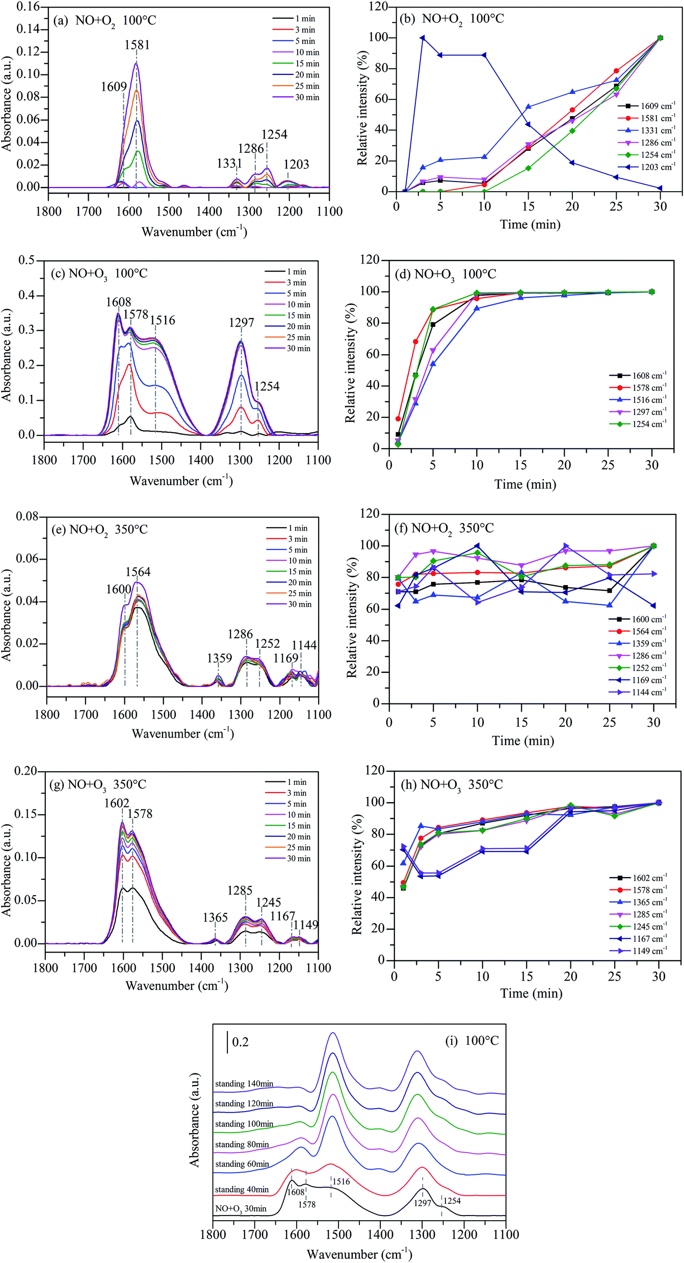
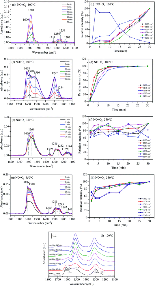
In situ DRIFTS studies of NOx adsorbed on 15%MnOx–CoOx(2:1)/TiO2 as a function of time were performed to reveal the effect of synergistic mechanism between 15%MnOx–CoOx(2:1)/TiO2 and O3 on NO oxidation. The fed gases were continued to introduce into the reaction cell for 1 h, and the infrared absorption spectra were recorded at intervals of one minute. Fig. 10(a) shows the temporal evolution of in situ DRIFTS curve during NO oxidation by O2 on 15%MnOx–CoOx(2:1)/TiO2 at 100 °C (NO = 500 ppm, O2 = 4%). After NO and O2 were introduced together into the DRIFTS cell, there was gradual appearance of peaks at 1609 cm−1 (bridging bidentate nitrates), 1581 cm−1 (bidentate nitrates), 1331 cm−1 (nitrate ions), 1254 cm−1 (bidentate nitrates), 1286 cm−1 (monodentate nitrates), and 1203 cm−1 (nitrites). The in situ DRIFTS curves in the range of 1100–1800 cm−1 were fitted by Gauss function to obtain the area of each sub-peak (for example, the sub-peaks at 1609 cm−1, 1581 cm−1, 1331 cm−1, 1286 cm−1, 1254 cm−1 and 1203 cm−1). The maximum area of each sub-peak during the first 30 minutes of reaction time was chosen as the standard. The relative intensity of each band was obtained by comparing the band area to the standard area. The slope of each relative intensity curve represented the rate of production or decomposition of each species. It can be seen clearly in Fig. 10(b) that the relative intensity of the peaks at 1609 cm−1, 1331 cm−1 and 1286 cm−1 progressively increased. Moreover, the peaks at 1581 cm−1 and 1254 cm−1 increased rapidly from 10 min and outpaced the other nitrate species. However, the peak at 1203 cm−1 appeared quickly within 3 min, and then declined especially after 10 min. These results indicated that nitrites were transformed or decomposed, which accelerated the production of bidentate nitrates.
 |
| | Fig. 10 In situ DRIFTS data of NO adsorbed on 15%MnOx–CoOx(2:1)/TiO2 as a function of time: (a) NO + O2 at 100 °C; (b) relative intensity of NO + O2 at 100 °C; (c) NO + O3 at 100 °C; (d) relative intensity of NO + O3 at 100 °C; (e) NO + O2 at 350 °C; (f) relative intensity of NO + O2 at 350 °C; (g) NO + O3 at 350 °C; (h) relative intensity of NO + O3 at 350 °C; (i) static reaction after NO and O3 adsorbed at 100 °C. | |
Fig. 10(c) shows the in situ DRIFTS curves during NO oxidation by O3 on 15%MnOx–CoOx(2:1)/TiO2 at 100 °C (NO = 500 ppm, O2 = 4%, O3/NO = 0.5). The peaks at 1608 cm−1 (bridging bidentate nitrates), 1578 cm−1 (bidentate nitrates), 1516 cm−1 (monodentate nitrates), 1297 cm−1 (monodentate nitrates) and 1254 cm−1 (bridging bidentate nitrates) appeared gradually. No characteristic peaks of nitrate ions and nitrites appeared which were consistent with the thermal stability test in Fig. 9(c). A new band appeared at 1516 cm−1 (monodentate nitrates) in the O3 oxidation system at 100 °C compared to Fig. 10(a). The intensity of the peak at 1608 cm−1 was higher than that of 1578 cm−1 and intensity of the peak at 1297 cm−1 was higher than that of 1254 cm−1 in Fig. 10(c) when compared with Fig. 10(a). This might due to that O3 accelerated the generation of bridging bidentate nitrates at 1608 cm−1, which promoted the production of monodentate nitrates at 1516 cm−1 and 1297 cm−1. The relative intensities of all species increased significantly within 10 min in Fig. 10(d), and then closed to adsorption saturation. By comparing the relative intensities in Fig. 10(b) and (d), it can be concluded that the oxidation of NO by O3 was much stronger than that by O2 on 15%MnOx–CoOx(2:1)/TiO2 at 100 °C.
Fig. 10(e) shows the in situ DRIFTS curves during NO oxidation by O2 on 15%MnOx–CoOx(2:1)/TiO2 at 350 °C (NO = 500 ppm, O2 = 4%). There were seven major bands located at 1600 cm−1 (bridging bidentate nitrates), 1564 cm−1 (bidentate nitrates), 1359 cm−1 (nitrate ion), 1286 cm−1 (monodentate nitrates), 1252 cm−1 (bidentate nitrates), 1169 cm−1 and 1144 cm−1 (nitrites). When NO and O2 were simultaneously injected into DRIFTS cell at 350 °C, all the bands appeared quickly within 1 min, but did not increase significantly thereafter. This indicated that the reaction of NO and O2 on the surface of 15%MnOx–CoOx(2:1)/TiO2 at 350 °C was rapid. Fig. 10(f) shows the relative intensity of each band. It can be seen that the relative intensities of all the species remained greater than 60%, indicating that the accumulation and decomposition of all the intermediate products were in dynamic equilibrium.
Fig. 10(g) presents the in situ DRIFTS curves during NO oxidation by O3 on 15%MnOx–CoOx(2:1)/TiO2 at 350 °C (NO = 500 ppm, O2 = 4%, O3/NO = 0.5). Similar to Fig. 10(e), seven peaks appeared within 1 min, including 1602 cm−1 (bridging bidentate nitrates), 1578 cm−1 (bidentate nitrates), 1365 cm−1 (nitrate ion), 1285 cm−1 (monodentate nitrates), 1245 cm−1 (bidentate nitrates), 1167 cm−1 and 1149 cm−1 (nitrites). The relative intensity of each intermediate species is presented in Fig. 10(h). All the bands in the presence of O3 at 350 °C rapidly generated but then grew slowly. Therefore, it can be concluded that the effect of ozone on the intermediates formed during catalytic oxidation was weakened at high temperature, but it still enhanced the NO catalytic oxidation. In addition, the peaks at 1167 cm−1 and 1149 cm−1 fluctuated greatly, indicating that there was partial decomposition of nitrites at 350 °C compared to that at 100 °C. Comparing the reaction of NO catalytic oxidation by O3 on 15%MnOx–CoOx(2:1)/TiO2 at 100 °C (Fig. 10(c)), there was no significant increase in monodentate nitrates around 1516 cm−1 and 1297 cm−1 during NO oxidation by O2 or O3 on 15%MnOx–CoOx(2:1)/TiO2 at 350 °C (Fig. 10(e) and (g)). In combination with the results of catalyst activity test, it was evident that the synergistic effect appeared only during NO oxidation by O3 (O3/NO = 0.5) on 15%MnOx–CoOx(2:1)/TiO2 below 250 °C (Fig. 8(e)). Thus, it can be speculated that monodentate nitrates were the pivotal intermediate products involved in the synergistic effect promoting the NO catalytic oxidation.
Fig. 10(i) presents the static reaction after NO and O3 co-adsorbed at 100 °C on 15%MnOx–CoOx(2:1)/TiO2. The peaks at 1608 cm−1 (bridging bidentate nitrates), 1578 cm−1 (bidentate nitrates), 1516 cm−1 (monodentate nitrates), 1297 cm−1 (monodentate nitrates) and 1254 cm−1 (bidentate nitrates) formed after NO and O3 co-adsorbed at 100 °C for 30 min. When all the gases were cut off and the adsorbed catalyst was left to stand for a period, the changes in the infrared absorption peaks of nitrate species were recorded. With the extension of the standing time, the characteristic peaks of bridging bidentate nitrates and bidentate nitrates at around 1608–1578 cm−1 were significantly reduced, while the characteristic peaks of monodentate nitrates at 1516 cm−1 and 1297 cm−1 were enhanced, and the peak at 1254 cm−1 was covered by the peak at 1297 cm−1. This indicated that bridging bidentate nitrates and bidentate nitrates could convert to monodentate nitrates.
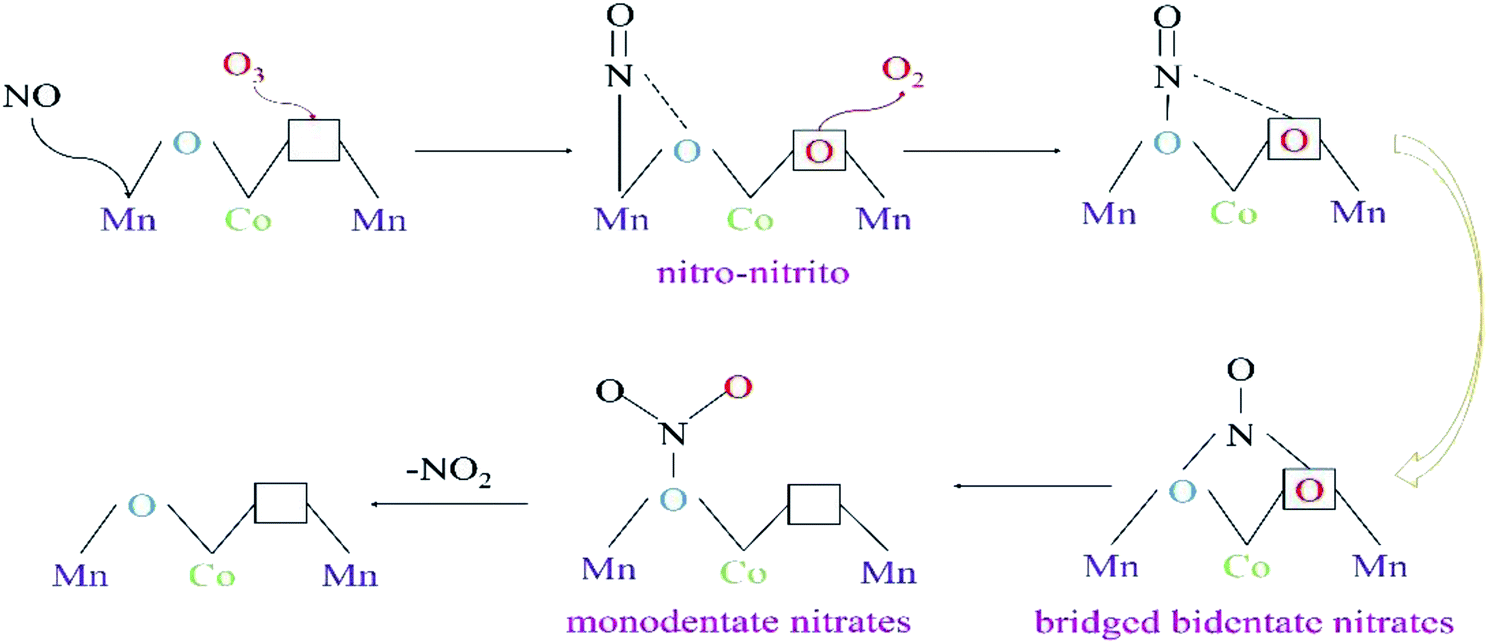
From the in situ DRIFTS tests of NOx desorption with increase in temperature, and the tests of NO oxidation by O3 or O2 using 15%MnOx–CoOx(2:1)/TiO2 at 100 °C and 350 °C, the transformations occurring between bridging bidentate nitrates, bidentate nitrates, monodentate nitrates and nitro–nitrito were determined. The results of characterization analyses showed that 15%MnOx–CoOx(2:1)/TiO2 contained oxygen vacancies, which could promote O3 to decompose an active oxygen atom at oxygen vacancy and desorbed an oxygen molecule.43 After NO reacted with active oxygen atom forming NO2, the oxygen vacancy was available to adsorb the next active oxygen atom.17 The pathway of NO catalytic oxidation by O3 using 15%MnOx–CoOx(2:1)/TiO2 is depicted in Fig. 11 and “□” represents oxygen vacancy.
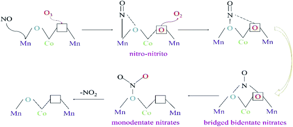 |
| | Fig. 11 The pathway of NO oxidation by O3 (O3/NO < 1) over 15%MnOx–CoOx(2:1)/TiO2. | |
In the in situ DRIFTS results of NOx desorption shown in Fig. 9, nitro–nitrito was formed on the surface of 15%MnOx–CoOx(2:1)/TiO2 after NO was adsorbed at 25 °C. Therefore, NO was adsorbed on the active metal atom of the catalyst to form nitro–nitrito, which then reacted with the adsorbed oxygen to form other nitrate species. The rise in reaction temperature accelerated the transformation and decomposition of nitrate species, leading to the increase in NO oxidation efficiency. However, in the in situ DRIFTS curves of NO oxidation by O3 on 15%MnOx–CoOx(2:1)/TiO2 at 100 °C (Fig. 10(c)), nitro–nitrito could not be observed. This was because it transformed to other nitrate species at 100 °C (Fig. 9(c)), especially to monodentate nitrates. Mass-produced monodentate nitrates could decompose into gaseous NO2, facilitating the oxidation of NO to NO2. This could be the reason for the synergistic effect on NO oxidation by O3 using 15%MnOx–CoOx(2:1)/TiO2 at low temperature.
4. Conclusions
In this work, TiO2-supported catalysts with various loading amounts of MnOx–CoOx (molar ratio of Mn to Co = 2:1) were prepared and evaluated in the oxidation of NO in presence of low ratio of O3 (O3/NO < 1). It was found that 15%MnOx–CoOx(2:1)/TiO2 displayed the optimal catalytic oxidation of NO due to its good redox performance, high surface oxygen mobility, most oxygen vacancies and chemisorbed oxygen. The NO oxidation efficiency was increased by O3 (O3/NO < 1) combined with 15%MnOx–CoOx(2:1)/TiO2 at 50–400 °C, especially below 250 °C. The synergistic effect of NO oxidation efficiency in the presence of O3 (O3/NO < 1) over 15%MnOx–CoOx(2:1)/TiO2 was observed below 250 °C. The results of in situ DRIFTS studies confirmed that O3 accelerated the transition between nitrate species, reduced the decomposition temperature of nitrate species, speeded up the rate of NO oxidation and inhibited the formation of nitrate ions. Below 250 °C, the mass-produced monodentate nitrates were responsible for the synergistic enhancement when both 15%MnOx–CoOx(2:1)/TiO2 and O3 were present. This conclusion can provide theoretical basis for the study of NO catalytic oxidation by low concentration ozone in the future.
Conflicts of interest
There are no conflicts to declare.
Acknowledgements
The project was supported by National Key Research and Development Program of China (2018YFB0605101), Key Project Natural Science Foundation of Tianjin (18JCZDJC39800), National Natural Science Foundation of China (51808181), the Science and Technology Key Project of Tianjin (18ZXSZSF00040, 18KPXMSF00080, 18PTZWHZ00010), Department of Education of Hebei Province (BJ2017032), Joint Doctoral Training Foundation of HEBUT (2017HW0002).
References
- D. Damma, P. R. Ettireddy, B. M. Reddy and P. G. Smirniotis, Catalysts, 2019, 9(4), 349 CrossRef CAS.
- J. Yang, Z. Su, S. Ren, H. Long, M. Kong and L. Jiang, J. Energy Inst., 2019, 92, 883–891 CrossRef CAS.
- M. Mladenović, M. Paprika and A. Marinković, Renewable Sustainable Energy Rev., 2018, 82, 3350–3364 CrossRef.
- C. Chen, Y. Cao, S. Liu, J. Chen and W. Jia, Chin. J. Catal., 2018, 39, 1347–1365 CrossRef CAS.
- I. Jõgi, E. Stamate, C. Irimiea, M. Schmidt, R. Brandenburg, M. Hołub, M. Bonisławski, T. Jakubowski, M.-L. Kääriäinen and D. C. Cameron, Fuel, 2015, 144, 137–144 CrossRef.
- Q. Ma, Z. Wang, F. Lin, M. Kuang, R. Whiddon, Y. He and J. Liu, Energy Fuels, 2016, 30, 2302–2308 CrossRef CAS.
- Q. Wu, C. Sun, H. Wang, T. Wang, Y. Wang and Z. Wu, Chem. Eng. J., 2018, 341, 157–163 CrossRef CAS.
- H. T. Li, F. Liu, S. H. Wang, F. J. Wang, X. Qian, C. D. Zhang, Y. L. Ma and L. D. Wang, Fuel Process. Technol., 2019, 194, 106125 CrossRef CAS.
- K. Li, X. Tang, H. Yi, P. Ning, D. Kang and C. Wang, Chem. Eng. J., 2012, 192, 99–104 CrossRef CAS.
- E. Park, S. Chin, J. Jeong and J. Jurng, Microporous Mesoporous Mater., 2012, 163, 96–101 CrossRef CAS.
- G. Qi and W. Li, Catal. Today, 2015, 258, 205–213 CrossRef CAS.
- D. Shang, Q. Zhong and W. Cai, Appl. Surf. Sci., 2015, 325, 211–216 CrossRef CAS.
- L. Qiu, Y. Wang, D. Pang, F. Ouyang, C. Zhang and G. Cao, Catalysts, 2016, 6, 9 CrossRef.
- H. Li, S. Wang, X. Wang, N. Tang, S. Pan and J. Hu, Fuel, 2017, 202, 470–482 CrossRef CAS.
- K. Skalska, J. S. Miller and S. Ledakowicz, Sci. Total Environ., 2010, 408, 3976–3989 CrossRef CAS PubMed.
- I. Jõgi, K. Erme, J. Raud and M. Laan, Fuel, 2016, 173, 45–51 CrossRef.
- F. Lin, Z. Wang, Q. Ma, Y. Yang, R. Whiddon, Y. Zhu and K. Cen, Appl. Catal., B, 2016, 198, 100–111 CrossRef CAS.
- C. Han, S. Zhang, L. Guo, Y. Zeng, X. Li, Z. Shi, Y. Zhang, B. Zhang and Q. Zhong, Chem. Eng. Res. Des., 2018, 136, 219–229 CrossRef CAS.
- D. Fang, J. Xie, H. Hu, H. Yang, F. He and Z. Fu, Chem. Eng. J., 2015, 271, 23–30 CrossRef CAS.
- L. J. Swain B and C. G. Lee, Arch. Metall. Mater., 2018, 63, 1037–1042 Search PubMed.
- J. Xie, D. Fang, F. He, J. Chen, Z. Fu and X. Chen, Catal. Commun., 2012, 28, 77–81 CrossRef CAS.
- X. Zhang, B. Shen, F. Shen, X. Zhang, M. Si and P. Yuan, Chem. Eng. J., 2017, 326, 551–560 CrossRef CAS.
- J. Han, D. Wang, Y. Du, S. Xi, J. Hong, S. Yin, Z. Chen, T. Zhou and R. Xu, J. Mater. Chem. A, 2015, 3, 20607–20613 RSC.
- J. Li, L. Li, W. Cheng, F. Wu, X. Lu and Z. Li, Chem. Eng. J., 2014, 244, 59–67 CrossRef CAS.
- Q. Liang, X. Wu, D. Weng and H. Xu, Catal. Today, 2008, 139, 113–118 CrossRef CAS.
- W. Li, C. Zhang, X. Li, P. Tan, A. Zhou, Q. Fang and G. Chen, Chin. J. Catal., 2018, 39, 1653–1663 CrossRef CAS.
- F. Gao, X. Tang, H. Yi, C. Chu, N. Li, J. Li and S. Zhao, Chem. Eng. J., 2017, 322, 525–537 CrossRef CAS.
- D. Meng, W. Zhan, Y. Guo, Y. Guo, L. Wang and G. Lu, ACS Catal., 2015, 5, 5973–5983 CrossRef CAS.
- P. Sudarsanam, B. Hillary, M. H. Amin, S. B. A. Hamid and S. K. Bhargava, Appl. Catal., B, 2016, 185, 213–224 CrossRef CAS.
- W. Tang, X. Wu, S. Li, X. Shan, G. Liu and Y. Chen, Appl. Catal., B, 2015, 162, 110–121 CrossRef CAS.
- M. Si, B. X. Shen, H. H. Zhang, L. J. Liu, W. J. Zhou, Z. Liu, Y. J. Pan and X. Zhang, Ind. Eng. Chem. Res., 2020, 59, 1467–1476 CrossRef CAS.
- H. Hu, S. Cai, H. Li, L. Huang, L. Shi and D. Zhang, J. Phys. Chem. C, 2015, 119, 22924–22933 CrossRef CAS.
- A. Chalkidis, D. Jampaiah, P. G. Hartley, Y. M. Sabri and S. K. Bhargava, Fuel Process. Technol., 2019, 193, 317–327 CrossRef CAS.
- W. Fan, H. Li, F. Zhao, X. Xiao, Y. Huang, H. Ji and Y. Tong, Chem. Commun., 2016, 52, 5316–5319 RSC.
- X. Zhang, B. Shen, X. Zhang, F. Wang, G. Chi and M. Si, RSC Adv., 2017, 7, 5928–5936 RSC.
- F. Wang, H. Dai, J. Deng, G. Bai, K. Ji and Y. Liu, Environ. Sci. Technol., 2012, 46, 4034–4041 CrossRef CAS PubMed.
- B. Meng, Z. Zhao, X. Wang, J. Liang and J. Qiu, Appl. Catal., B, 2013, 129, 491–500 CrossRef CAS.
- L. Zhang, L. Shi, L. Huang, J. Zhang, R. Gao and D. Zhang, ACS Catal., 2014, 4, 1753–1763 CrossRef CAS.
- F. Lin, Z. Wang, Z. Zhang, Y. He, Y. Zhu, J. Shao, D. Yuan, G. Chen and K. Cen, Chem. Eng. J., 2019, 382, 123030 CrossRef.
- H. Hu, K. Zha, H. Li, L. Shi and D. Zhang, Appl. Surf. Sci., 2016, 387, 921–928 CrossRef CAS.
- Y. Yu, J. Wang, J. Chen, X. Meng, Y. Chen and C. He, Ind. Eng. Chem. Res., 2014, 53, 16229–16234 CrossRef CAS.
- N. Tang, Y. Liu, H. Wang and Z. Wu, J. Phys. Chem. C, 2011, 115, 8214–8220 CrossRef CAS.
- V. P. Santos, M. F. R. Pereira, J. J. M. Órfão and J. L. Figueiredo, Appl. Catal., B, 2010, 99, 353–363 CrossRef CAS.
Footnote |
| † Electronic supplementary information (ESI) available. See DOI: 10.1039/d0ra04129g |
|
| This journal is © The Royal Society of Chemistry 2020 |
Click here to see how this site uses Cookies. View our privacy policy here. 
 Open Access Article
 This Open Access Article is licensed under a Creative Commons Attribution-Non Commercial 3.0 Unported Licence
 a,
Boxiong Shen*a,
Lijun Liua,
Haohao Zhanga,
Wenjun Zhoua,
Jianqiao Wanga,
Xiao Zhanga,
Zhikun Zhanga and
Chunfei Wub
a,
Boxiong Shen*a,
Lijun Liua,
Haohao Zhanga,
Wenjun Zhoua,
Jianqiao Wanga,
Xiao Zhanga,
Zhikun Zhanga and
Chunfei Wub