 Open Access Article
Creative Commons Attribution 3.0 Unported Licence
Highly crystalline nickel hexacyanoferrate as a long-life cathode material for sodium-ion batteries
Ratul Rehman,
Jian Peng*,
Haocong Yi,
Yi Shen,
Jinwen Yin,
Chang Li,
Chun Fang,
Qing Li and
Jiantao Han
 *
*
School of Materials Science and Engineering, State Key Laboratory for Materials Processing and Die & Mould Technology, Huazhong University of Science and Technology, Wuhan 430074, People's Republic of China. E-mail: pj9301@hust.edu.cn; jthan@hust.edu.cn
First published on 21st July 2020
Abstract
Prussian blue analogs (PBAs) are attractive cathode candidates for high energy density, including long life-cycle rechargeable batteries, due to their non-toxicity, facile synthesis techniques and low cost. Nevertheless, traditionally synthesized PBAs tend to have a flawed crystal structure with a large amount of [Fe(CN)6]4− openings and the presence of crystal water in the framework; therefore the specific capacity achieved has continuously been low with poor cycling stability. Herein, we demonstrate low-defect and sodium-enriched nickel hexacyanoferrate nanocrystals synthesized by a facile low-speed co-precipitation technique assisted by a chelating agent to overcome these problems. As a consequence, the prepared high-quality nickel hexacyanoferrate (HQ-NiHCF) exhibited a high specific capacity of 80 mA h g−1 at 15 mA g−1 (with a theoretical capacity of ∼85 mA h g−1), maintaining a notable cycling stability (78 mA h g−1 at 170 mA g−1 current density) without noticeable fading in capacity retention after 1200 cycles. This low-speed synthesis strategy for PBA-based electrode materials could be also extended to other energy storage materials to fabricate high-performance rechargeable batteries.
Introduction
Lithium-ion batteries (LIBs) are well known in application and are gaining significant interest for energy-storage applications.1–5 Although LIBs have numerous advantages, such as long cycling life, high recycling efficiency and high energy density, which meet the necessary requirements for electrical energy storage systems (EESs), the cost of lithium is one point that ought to be given more consideration from the perspective of large-scale usage. Latterly, the cost of lithium has been escalating rapidly, owing to the irregular circulation of worldwide lithium reserves.6 To address this challenge, sodium-ion batteries (SIBs) have become a progressively more appealing option to LIBs in EESs because of their low cost and elongated lifecycle.7,8 Besides, the chemical attributes of sodium show similar properties and comparing its source, sodium has more plentiful sources than lithium, and thus different types of cathode materials have been contemplated for SIBs.In recent years, metal–organic frameworks (MOFs) have been prevalent in considering this purpose.9–11 Because of their moderately low capacity value,12,13 including poor rate performance,14 and competition with their anode counterparts,15–17 cathode materials are of immense significance in hastening the commercialization of SIBs. However, a significant distortion of and strain on the crystal lattice may be induced due to the broad radius of Na+ during the incorporation phase, and this also poses challenges in finding relevant electrode materials for SIBs.18–21 Some cathodes, P2–Na0.67Co1−xTixO2,22 Na3V2(PO4)3,23,24 NaTi2(PO4)3,25,26 and Na0.7[Mn1−xLix]O2+y,27 demonstrated significant performance in terms of variable capacity, including rate efficiency, but due to certain phase transitions, and large changes in volume during cycling, they have failed to meet long cycling-life requirements. Prussian blue analogs (PBAs), a kind of metal–organic framework with the formula AxMy[M′(CN)6]z·nH2O, where A refers to an alkaline metal and M, M′ refer to transition metals, have been widely studied as attractive cathodes for SIBs in the past decade due to their high theoretical capacity and long-cycle life. As a significant cathode source for Na-ion batteries, PBAs have been given a lot of attention, not only for their rigid open framework (which can ensure suitable Na+ flexibility with large-scale interstitial sites) but also since they present a volume difference between Na+ insertion and extraction.28–31 Also, their facile synthetic procedure makes them suitable for large-scale applications, besides their nontoxicity and low cost, and they have become more widespread.32,33 The open crystal structure could effectively tolerate flexibility in the lattice volume and facilitate the passage of Na+.34–40
However, the theoretical value of specific capacity for PBAs is still unreachable, apart from their poor cycling stability and low coulombic efficiency, due to defects and crystal water in the framework of PBAs.34,41,42 Earlier it was proved that the electrochemical performance of PBAs is firmly identified with their inherent crystal structure.43,44 In our research group, synthesized CeHCF as a cathode material performed with a specific capacity of ∼60 mA h g−1 at 0.25C (with capacity retention of about ∼80% at 8.3C) in LIBs, and similarly ∼55 mA h g−1 at 0.25C (with capacity retention of nearly 55% at 8.3C) in SIBs, due to an open network with large lattice spaces.45 Additionally, recently some innovative work has reported on PBAs based upon long-term cyclability and improved electrochemical kinetics as well efficiency.46–49 Guo's group revealed that the suitability of K0.09Ni[Fe(CN)6]0.71·6H2O as a cathode for SIBs was attributed to its zero-strain characteristics, where there was less than 1% change in lattice parameter distortion during the Na+ insertion/extraction phase50 and it achieved excellent cycling stability and a highly stable structure. Jiang's group also reported remarkable cycling stability from synthesized Na1.014Ni[Fe(CN)6]0.818·3.53H2O via a simple co-precipitation method, but the specific capacity was as low as 68 mA h g−1.51 Nevertheless, in practical applications, the tested AxNi[Fe(CN)6]y cathodes could not carry more sodium content and presented a high number of defects in crystallization. To increase the content of sodium in the framework, Liu's group firstly came up with the idea where different amounts of sodium citrate were employed in the synthesis process as a cathode material for SIBs.52 Recently, another study has been done on highly stable monoclinic sodium-rich nickel hexacyanoferrate by introducing tri-sodium citrate to control its crystallization.53 Henceforth, when designing a new cathode, it is important that the sodium content should be high with fine crystallization and meet the requirements of applications, such as temperature adaptability, steadiness and more. The preparation of nickel–iron Prussian blue analogs (Ni–Fe PBAs) has often shown a significant amount of vacancies within the crystal structure due to quick precipitation via the conventional synthesis process.54
In this research, we have established low-defect and sodium-rich nickel hexacyanoferrate nanocrystals synthesized through a simple co-precipitation mechanism with the assistance of a chelating agent called tri-sodium citrate. Because of the moderate development process for crystallization, HQ-NiHCF displayed a small zeolite water content with few [Fe(CN)6]4− openings in the crystal structure. For these reasons, the ion storage ability was significantly improved and there were adequate transportation behaviors for Na+ and e−, as well as effective preservation of the integrity of the crystal structure during cycling. Hence, in terms of its good specific capacity of nearly 80 mA h g−1, which is very close to the theoretical value, remarkable cycling stability of 78 mA h g−1 around 1200 cycles, and superb rate capability of 62 mA h g−1 at 10C with high coulombic efficiency, it has shown persuasive electrochemical performance as a cathode for SIBs. For comparison purposes, low-quality nickel hexacyanoferrate (LQ-NiHCF) was also synthesized by the conventional procedure without any additive, and the relative performances are offered in our report.
Experimental
Synthesis route of HQ-NiHCF and LQ-NiHCF
The HQ-NiHCF PBA was synthesized by an enhanced co-precipitation technique where we added tri-sodium citrate (Na3C6H5O7·2H2O) as a chelating agent.52 To make solution A, 5 mmol of NiCl2·6H2O and 5 mmol of Na3C6H5O7·2H2O were dissolved in 50 ml of distilled water. Afterward, to prepare solution B, 5 mmol of Na4Fe(CN)6 was dissolved in 50 ml of deionized water. Finally, to form solution C, 0.5 g of polyvinylpyrrolidone K-30 (PVP) was gradually mixed in 200 ml of deionized water. Then solutions A and B were added directly to solution C under nonstop stirring for 2 h, and aged at room temperature for 24 h. From that point onward, the sediment was gathered by centrifugation and washed with deionized water several times (minimum 3 times) and washed with ethanol once. The sediment was eventually dried in a vacuum oven at 100 °C for 24 h and the HQ-NiHCF PBA was collected.In general, the synthesis of LQ-NiHCF PBA was done by the precipitation method. Typically, 5 mmol of NiCl2.6H2O was dissolved in 50 ml of deionized water to develop solution A. Then a 5 mmol volume of Na4Fe(CN)6 was mixed in 50 ml of deionized water to get solution B. Finally, to produce solution C, 0.5 g of PVP K-30 was mixed in 200 ml of deionized water until it dissolved. Now, by using a peristaltic pump, solution (A) and (B) were added to solution (C) until there was no dribbling, at which point it was kept under stirring for 6 h, then aged for 24 h and similar procedures were pursued to those above to obtain samples.
Materials characterization
The XRD patterns were recorded with a Panalytical X'pert PRO MRD (Holland) using Cu Kα radiation. Scanning electron microscopy (SEM, TESCAN VEGA3) and transmission electron microscopy (TEM, JEM-2100 electron microscope) were used to analyze the morphologies of the samples as well as their sizes. The thermal evaluation curve was analyzed with a thermogravimetric analyzer (TGA, Netzsch STA 449 F3) under an air atmosphere from room temperature to 620 °C at a heating rate of 10 °C min−1. The elements were identified using an elemental analyzer (Vario Micro), and the chemical composition of the Fe, Ni and Na elements was studied by inductively coupled plasma optical emission spectroscopy (ICP-OES, IRIS Intrepid II XSP, Thermo Elemental, USA).Electrochemical measurements
The working electrodes were designed by mixing the active ingredients, Ketjen black and polytetrafluoroethylene in a weight ratio of 7![[thin space (1/6-em)]](https://www.rsc.org/images/entities/char_2009.gif) :
:![[thin space (1/6-em)]](https://www.rsc.org/images/entities/char_2009.gif) 2
2![[thin space (1/6-em)]](https://www.rsc.org/images/entities/char_2009.gif) :
:![[thin space (1/6-em)]](https://www.rsc.org/images/entities/char_2009.gif) 1 to form a slurry, transferred to an aluminium mesh, and eventually pressed to fabricate a thin film, then vacuum dried at 100 °C. To assess electrochemical efficiency, a regular coin-cell (CR2032) was assembled where metallic sodium was used as the counter-electrode. For an electrolyte, 1.0 mol L−1 NaClO4 in a solution of ethylene carbonate/diethyl carbonate (1
1 to form a slurry, transferred to an aluminium mesh, and eventually pressed to fabricate a thin film, then vacuum dried at 100 °C. To assess electrochemical efficiency, a regular coin-cell (CR2032) was assembled where metallic sodium was used as the counter-electrode. For an electrolyte, 1.0 mol L−1 NaClO4 in a solution of ethylene carbonate/diethyl carbonate (1![[thin space (1/6-em)]](https://www.rsc.org/images/entities/char_2009.gif) :
:![[thin space (1/6-em)]](https://www.rsc.org/images/entities/char_2009.gif) 1 vol) with 2 wt% fluoroethylene carbonate was used with Whatman glass fibers as a separator. Each of the cells was installed in an Ar-filled glove box at room temperature. The cyclic voltammetry (CV) curves were measured on an electrochemical workstation (Princeton) at 0.1 mV s−1 and the galvanostatic charge/discharge experiments were carried out on a battery testing system (LAND cycler, Wuhan Kingnuo Electronic) from 2.0 to 4.2 V versus Na+/Na.
1 vol) with 2 wt% fluoroethylene carbonate was used with Whatman glass fibers as a separator. Each of the cells was installed in an Ar-filled glove box at room temperature. The cyclic voltammetry (CV) curves were measured on an electrochemical workstation (Princeton) at 0.1 mV s−1 and the galvanostatic charge/discharge experiments were carried out on a battery testing system (LAND cycler, Wuhan Kingnuo Electronic) from 2.0 to 4.2 V versus Na+/Na.
Results and discussion
Structure analysis and chemical properties
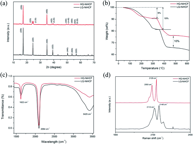
According to the XRD results in Fig. 1a, we noted that the typical PBAs achieved a face-centered cubic structure.55 The peaks (220), (420), (440) of HQ-NiHCF were split into almost equal forces which was due to the expansion of the crystal lattice and decrease in symmetry caused by the large amount of sodium ions in the crystal structure. The enhanced crystallinity was mainly due to the low-speed co-preparation methods, resulting in an intact crystal.11,34,56,57 Through the conventional precipitation process, LQ-NiHCF suffered very poor crystallization. The reason is that the growth stage and nucleation of Na2Ni[Fe(CN)6] happened immediately, later causing a large amount of Fe(CN)6 defects, and synchronized water molecules in the crystal framework. However, in the chelating agent-assisted co-precipitation method, tri-sodium citrate (Na3C6H5O7·2H2O) was co-precipitated with a solution of sodium ferrocyanide, which basically suppressed the rate of growth and achieved a superbly crystallized Na2Ni[Fe(CN)6] sample. The formulae of LQ-NiHCF PBAs and HQ-NiHCF PBAs were determined to be Na0.79Ni[Fe(CN)6]0.74, and Na1.67Ni[Fe(CN)6]0.87, corresponding to 26% and 13% defect contents, respectively.The amount of water content and the material degradation process were studied by TGA, as shown in Fig. 1b. Here, there were noticeable weight losses of 9% and 19% below a temperature of 200 °C for HQ-NiHCF and LQ-NiHCF, respectively, resulting from the weight loss of water content in the sample, attributed to adsorbed water loosely bonded with the particle surfaces, including the frameworks.58,59 There was less weight loss for HQ-NiHCF because of its synthesis method where water coordination was reduced. Furthermore, the final material degradation for both materials at high temperature (>500 °C) showed that the newly fabricated samples were almost 10% more efficient than the generally synthesized LQ-NiHCF. The chemical bonds were examined in the structures and the presence of contamination was determined using Fourier-transform infrared (FT-IR) spectra.60 From the position of the absorption peaks for these two samples in Fig. 1c, it can be seen that both samples were consistent with indications of the existence of the same functional groups. The strong absorption peak at 2094 cm−1 corresponded to the elongating vibrations of the C![[triple bond, length as m-dash]](https://www.rsc.org/images/entities/char_e002.gif) N ligands coordinated with Fe2+ and Ni2+.61 The absorption points at 1622 cm−1 and the area between 3300 and 3500 cm−1 could be ascribed to the O–H bending vibrations and stretching O–H modes, respectively, due to interstitial water.62
N ligands coordinated with Fe2+ and Ni2+.61 The absorption points at 1622 cm−1 and the area between 3300 and 3500 cm−1 could be ascribed to the O–H bending vibrations and stretching O–H modes, respectively, due to interstitial water.62
Raman spectroscopy was used to explain the change in valance state of iron in the compound, as shown in Fig. 1d. Both samples achieved almost the same peaks in the diagram. The two peaks traced at 2093 and 2129 cm−1 for HQ-NiHCF and the peaks at 2112 and 2148 cm−1 for LQ-NiHCF, are attributed to the vibrations of the cyanide group and show that Fe and Ni ions exhibited divalent ions and almost two Na ions existed in the materials (FeII–C![[triple bond, length as m-dash]](https://www.rsc.org/images/entities/char_e002.gif) N–NiII).63 According to the increased intensity of the peaks, it can be speculated that the number of Na ions increased with the slow reaction rate in the synthesis of HQ-NiHCF.
N–NiII).63 According to the increased intensity of the peaks, it can be speculated that the number of Na ions increased with the slow reaction rate in the synthesis of HQ-NiHCF.
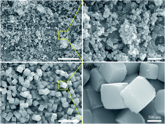
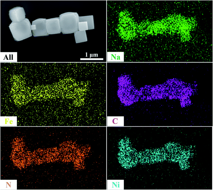
SEM was used to explain the size of the nanoparticles of the as-prepared samples. Here, the different magnification images of the LQ-NiHCF sample shown in Fig. 2a and b were composed of erratically rough agglomeration particles due to the conventional precipitation processes where the crystallization and growth occurred so fast.44 In contrast, due to the deceleration and segregation of crystal growth, HQ-NiHCF in Fig. 2c and d displays uniform nanocubes. With the assistance of the chelating agent, the nucleation kinetics and crystal aggregation are reduced. By using energy dispersive spectroscopy (EDS) mapping, Na, Fe, and Ni elements were confirmed in the HQ-NiHCF samples, as shown in Fig. 3. Moreover, its high purity and integrity can be suggested, as these components are homogeneously distributed throughout the materials.34 The TEM images are shown in Fig. 4, where in Fig. 4(a and b) it can be seen that the LQ-NiHCF sample was polycrystalline. The sample HQ-NiHCF presented an electron diffraction pattern showing single particle nanocrystals, and the SAED patterns (as inset in Fig. 4b and d) also supported the high crystallinity of the samples, as shown in Fig. 4(c and d). It can be perceived that this kind of nano-cubic structure could be very suitable for Na+ and e− transportation in the electrochemical reaction phase.
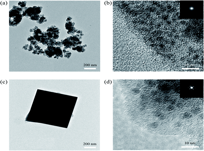 | ||
| Fig. 4 (a) and (b) TEM images of the polycrystalline LQ-NiHCF PBA with SAED patterns (inset); (c) and (d) TEM images of single-particle HQ-NiHCF PBA nanocrystals with SAED patterns (inset). | ||
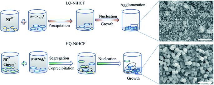
Based on the aforementioned experimental data, a probable mechanism for the growth of HQ-NiHCF nanocubes is suggested and shown in Scheme 1. In general, in the conventional precipitation process synthesis, Ni2+ cations responded to [Fe(CN)6]4− anions in the aqueous solution. Here, the nucleation and growth stage happened instantly, and therefore the particles accumulated together, with large amounts of [Fe(CN)6]4− flaws also corresponding to water inside the framework. Citrate, by playing the main role in controlling the speed of agitation and segregating molecules, helped form perfectly shaped nanocubes with prominently inhibited [Fe(CN)6]4− defects. In the chelating agent-assisted method, the Ni2+ ions firstly linked with citrate ions and formed a nickel-citrate chelate, and afterward co-precipitated in aqueous solution with hexacyanoferrate ions. The nickel-citrate chelate served as a buffer for gradually releasing Ni2+ ions to interact with hexacyanoferrate ions to form initial nucleuses. Due to the high multifaceted potential of citrate ions and their carrying a negative charge, they accumulated uniformly on the nucleus surfaces, thereby overturning the rate of growth and suppressing the aggregation of crystals. Eventually, the slow growth and constant release of Ni ions helped these nucleuses to develop well-formed monodispersed Prussian blue nanocubes with high crystallinity.
Electrochemical properties testing
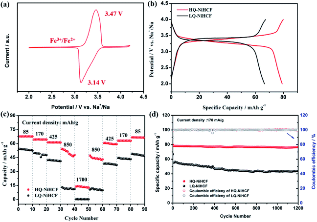
Electrochemical performances were studied by galvanostatic charge/discharge and cyclic voltammetry (CV). Fig. 5a shows the CV of HQ-NiHCF at a scan rate of 0.1 mV s−1 within 2.0 and 4.2 V (vs. Na+/Na) where a pair of distinct reduction/oxidation peaks appeared at 3.47/3.14 V, correlating with the balance potential of Fe2+/Fe3+;64 Ni2+ remains electrochemically inert for the sodium reaction.31,65 From Fig. 5b it can be seen that the initial charge and discharge capacities of HQ-NiHCF are 79.93 and 79.19 mA h g−1, respectively, at a current density of 15 mA g−1, which is consistent with a coulombic efficiency of almost 99% while LQ-NiHCF delivers lower charge/discharge capacities of 67.43 and 66.55 mA h g−1, respectively. Here, Na+ storage sites were utilized more in HQ-NiHCF, and thus it can be ascribed to the high crystallinity and reduced water content inside the crystal framework together with a lower number of [Fe(CN)6] vacancies.34,66 In the fast charge/discharge process, HQ-NiHCF achieves an enhanced rate capability. Fig. 5c shows the rate performance of HQ-NiHCF and LQ-NiHCF, where HQ-NiHCF shows a higher overall specific capacity than LQ-NiHCF, and the specific discharge capacities of HQ-NiHCF are 78, 74, 70, 63 mA h g−1 from 85 to 850 mA g−1, which remained incredibly stable without any obvious capacity loss over 90 cycles once the current changed back to 85 mA g−1. However, LQ-NiHCF could not hold any capacity and only maintained ∼47 mA h g−1 at 425 mA g−1. In practical applications, the cycling performance and the coulombic efficiency play an endlessly significant role.67 Moreover, HQ-NiHCF showed a dramatically improved cycling performance compared to LQ-NiHCF. Fig. 5d presents the long cycling behavior of HQ-NiHCF beneath a current density of 170 mA h g−1 and LQ-NiHCF was also tested for comparison. Although LQ-NiHCF performed with excellent cyclic stability but a low discharge capacity of 57 mA h g−1, it exhibited a declining drift with a very poor coulombic efficiency. Remarkably, the HQ-NiHCF cathode carried a high discharge capacity of 78 mA h g−1 and capacity retention of ∼98% after 1200 cycles. While charging, a side reaction happened with zeolite water, and therefore the coulombic efficiency was a little lower for only the first few cycles, but later on, it jumped to more than 98%, which is considerably more than that of LQ-NiHCF, as shown in Fig. 6a and b. The capacity retention at different current densities was also observed, through long-term cycling, as shown in Fig. 6c and d, where it is clearly indicated that HQ-NiHCF held its capacity of almost 62 mA h g−1 at 10C but LQ-NiHCF retained only 13.7 mA h g−1.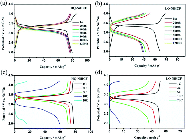 | ||
| Fig. 6 Cycle performance of: (a) HQ-NiHCF; (b) LQ-NiHCF, and the rate performance of (c) HQ-NiHCF; (d) LQ-NiHCF. | ||
Such an improvement in the efficiency of Na-storage could be associated with Na-ion intercalation habits, the lower amount of water and the resulting improved crystallinity of HQ-NiHCF. These findings specify that the physical steadiness of the PBAs can be considerably improved by enriching the quality of the crystal structure. The abovementioned finding also verifies that the advent of PBAs with high-quality crystal structures will lead to progress in their applications.
Conclusions
In summary, we have effectively fabricated low-defect and Na-rich nickel hexacyanoferrate nano-particles by introducing a chelating agent. Here, tri-sodium citrate acted to slow down the crystallization speed and achieved perfectly shaped crystalline particles. Due to the suppressed amount of [Fe(CN)6]4− vacancies, including water molecules, in the framework, the HQ-NiHCF PBA exhibited a high specific capacity of 80 mA h g−1 at 15 mA g−1, and the cycling stability after 1200 cycles still remained at 99%, and 78 mA h g−1 of the capacity delivered at a current density of 170 mA g−1 and an excellent rate capability of 63 mA h g−1 at 850 mA g−1. Although it showed a lower specific capacity, considering its excellent electrochemical performance, simple method of synthesis and low cost, the application of HQ-NiHCF is a promising cathode material for SIBs in the large-scale energy storage systems.Conflicts of interest
There are no conflicts to declare.Acknowledgements
This research was supported by the National Key R&D Program (Grant 2016YFB0100302), and the National Natural Science Foundation (Grants 51772117 and 51732005) of China. The authors also praise to the Analytical and Testing Centre of HUST and the State Key Laboratory of Materials Processing and Die & Mold Technology of HUST for XRD, SEM, TEM, Raman, TGA, and other tests.References
- J. Unger, C. Hametner, S. Jakubek and M. Quasthoff, J. Power Sources, 2014, 269, 883–897 CrossRef CAS
.
- X. Han, M. Ouyang, L. Lu and J. Li, J. Power Sources, 2014, 268, 658–669 CrossRef CAS
.
- L. Chen and L. L. Shaw, J. Power Sources, 2014, 267, 770–783 CrossRef CAS
.
- S. Pan, Z. Zhang, W. Weng, H. Lin, Z. Yang and H. Peng, Mater. Today, 2014, 17, 276–284 CrossRef CAS
.
- M. A. Hannan, M. S. H. Lipu, A. Hussain and A. Mohamed, Renew. Sustain. Energy Rev., 2017, 78, 834–854 CrossRef
.
- L. Kavanagh, J. Keohane, G. G. Cabellos, A. Lloyd and J. Cleary, Resources, 2018, 7(3), 57–85 CrossRef
.
- N. S. Choi, Z. Chen, S. A. Freunberger, X. Ji, Y. K. Sun, K. Amine, G. Yushin, L. F. Nazar, J. Cho and P. G. Bruce, Angew. Chem., Int. Ed., 2012, 51, 9994–10024 CrossRef CAS PubMed
.
- J. Y. Hwang, S. T. Myung and Y. K. Sun, Chem. Soc. Rev., 2017, 46, 3529–3614 RSC
.
- S. Furukawa, J. Reboul, S. Diring, K. Sumida and S. Kitagawa, Chem. Soc. Rev., 2014, 43, 5700–5734 RSC
.
- L. Gou, L. M. Hao, Y. X. Shi, S. L. Ma, X. Y. Fan, L. Xu, D. L. Li and K. Wang, J. Solid State Chem., 2014, 210, 121–124 CrossRef CAS
.
- J. Peng, J. Wang, H. Yi, W. J. Hu, Y. Yu, J. Yin, Y. Shen, Y. Liu, J. Luo, Y. Xu, P. Wei, Y. Li, Y. Jin, Y. Ding, L. Miao, J. Jiang, J. Han and Y. Huang, Adv. Energy Mater., 2018, 8, 1702856 CrossRef
.
- D. Kim, S. H. Kang, M. Slater, S. Rood, J. T. Vaughey, N. Karan, M. Balasubramanian and C. S. Johnson, Adv. Energy Mater., 2011, 1, 333–336 CrossRef CAS
.
- Z. Jian, L. Zhao, H. Pan, Y. S. Hu, H. Li, W. Chen and L. Chen, Electrochem. Commun., 2012, 14, 86–89 CrossRef CAS
.
- D. Yuan, W. He, F. Pei, F. Wu, Y. Wu, J. Qian, Y. Cao, X. Ai and H. Yang, J. Mater. Chem. A, 2013, 1, 3895–3899 RSC
.
- S. Komaba, W. Murata, T. Ishikawa, N. Yabuuchi, T. Ozeki, T. Nakayama, A. Ogata, K. Gotoh and K. Fujiwara, Adv. Funct. Mater., 2011, 21, 3859–3867 CrossRef CAS
.
- V. Palomares, P. Serras, I. Villaluenga, K. B. Hueso, J. Carretero-González and T. Rojo, Energy Environ. Sci., 2012, 5, 5884–5901 RSC
.
- J. Qian, Y. Chen, L. Wu, Y. Cao, X. Ai and H. Yang, Chem. Commun., 2012, 48, 7070–7072 RSC
.
- H. Kim, H. Kim, Z. Ding, M. H. Lee, K. Lim, G. Yoon and K. Kang, Adv. Energy Mater., 2016, 6(19), 1600943–1600980 CrossRef
.
- D. Yuan, X. Hu, J. Qian, F. Pei, F. Wu, R. Mao, X. Ai, H. Yang and Y. Cao, Electrochim. Acta, 2014, 116, 300–305 CrossRef CAS
.
- Y. Qiao, R. Han, Y. Liu, M. Ma, X. Cheng, Q. Li, H. Yue, Z. Cao, H. Zhang and S. Yang, Chem.–Eur. J., 2017, 23, 16051–16058 CrossRef CAS
.
- Y. Liu, Y. Qiao, G. Wei, S. Li, Z. Lu, X. Wang and X. Lou, Energy Storage Mater., 2018, 11, 274–281 CrossRef
.
- S. M. Kang, J. H. Park, A. Jin, Y. H. Jung, J. Mun and Y. E. Sung, ACS Appl. Mater. Interfaces, 2018, 10, 3562–3570 CrossRef CAS PubMed
.
- D. Guo, J. Qin, Z. Yin, J. Bai, Y. K. Sun and M. Cao, Nano Energy, 2018, 45, 136–147 CrossRef CAS
.
- X. Li, Y. Huang, J. Wang, L. Miao, Y. Li, Y. Liu, Y. Qiu, C. Fang, J. Han and Y. Huang, J. Mater. Chem. A, 2018, 6, 1390–1396 RSC
.
- L. Zhang, X. Wang, W. Deng, X. Zang, C. Liu, C. Li, J. Chen, M. Xue, R. Li and F. Pan, Nanoscale, 2018, 10, 958–963 RSC
.
- Q. Hu, M. Yu, J. Liao, Z. Wen and C. Chen, J. Mater. Chem. A, 2018, 6, 2365–2370 RSC
.
- M. S. Kwon, S. G. Lim, Y. Park, S. M. Lee, K. Y. Chung, T. J. Shin and K. T. Lee, ACS Appl. Mater. Interfaces, 2017, 9, 14758–14768 CrossRef CAS PubMed
.
- H. Lee, Y. Il Kim, J. K. Park and J. W. Choi, Chem. Commun., 2012, 48, 8416–8418 RSC
.
- T. Matsuda, M. Takachi and Y. Moritomo, Chem. Commun., 2013, 49, 2750–2752 RSC
.
- L. Wang, Y. Lu, J. Liu, M. Xu, J. Cheng, D. Zhang and J. B. Goodenough, Angew. Chem., Int. Ed., 2013, 52, 1964–1967 CrossRef CAS PubMed
.
- C. D. Wessells, S. V. Peddada, R. A. Huggins and Y. Cui, Nano Lett., 2011, 11, 5421–5425 CrossRef CAS PubMed
.
- Y. Mizuno, M. Okubo, K. Kagesawa, D. Asakura, T. Kudo, H. Zhou, K. Oh-Ishi, A. Okazawa and N. Kojima, Inorg. Chem., 2012, 51, 10311–10316 CrossRef CAS
.
- D. F. Goldspink, S. E. M. Lewis and B. J. Merry, Cardiovasc. Res., 1986, 20, 672–678 CrossRef CAS PubMed
.
- X. Wu, C. Wu, C. Wei, L. Hu, J. Qian, Y. Cao, X. Ai, J. Wang and H. Yang, ACS Appl. Mater. Interfaces, 2016, 8, 5393–5399 CrossRef CAS PubMed
.
- D. S. Kim, M. B. Zakaria, M. S. Park, A. Alowasheeir, S. M. Alshehri, Y. Yamauchi and H. Kim, Electrochim. Acta, 2017, 240, 300–306 CrossRef CAS
.
- Y. Lu, L. Wang, J. Cheng and J. B. Goodenough, Chem. Commun., 2012, 48, 6544–6546 RSC
.
- M. B. Zakaria and T. Chikyow, Coord. Chem. Rev., 2017, 352, 328–345 CrossRef CAS
.
- M. J. Piernas-Muñoz, E. Castillo-Martínez, J. L. Gómez-Cámer and T. Rojo, Electrochim. Acta, 2016, 200, 123–130 CrossRef
.
- Y. Liu, G. Wei, M. Ma and Y. Qiao, Chem.–Eur. J., 2017, 23, 15991–15996 CrossRef CAS PubMed
.
- Y. Liu, D. He, R. Han, G. Wei and Y. Qiao, Chem. Commun., 2017, 53, 5569–5572 RSC
.
- J. Yin, Y. Shen, C. Li, C. Fan, S. Sun, Y. Liu, J. Peng, L. Qing and J. Han, ChemSusChem, 2019, 12, 4786–4790 CrossRef CAS PubMed
.
- J. Song, L. Wang, Y. Lu, J. Liu, B. Guo, P. Xiao, J. J. Lee, X. Q. Yang, G. Henkelman and J. B. Goodenough, J. Am. Chem. Soc., 2015, 137, 2658–2664 CrossRef CAS PubMed
.
- X. H. Ma, W. Jia, J. Wang, J. H. Zhou, Y. D. Wu, Y. Y. Wei, Z. F. Zi and J. M. Dai, Ceram. Int., 2019, 45, 740–746 CrossRef CAS
.
- M. Okubo, D. Asakura, Y. Mizuno, T. Kudo, H. Zhou, A. Okazawa, N. Kojima, K. Ikedo, T. Mizokawa and I. Honma, Angew. Chem., Int. Ed., 2011, 50, 6269–6273 CrossRef CAS PubMed
.
- J. Peng, C. Li, J. Yin, J. Wang, Y. Yu, Y. Shen, J. Fang, A. Chen, Y. Xu, R. Rehman, C. Fang, L. Miao, R. Jiang, Q. Li, J. Han and Y. Huang, ACS Appl. Energy Mater., 2019, 2, 187–191 CrossRef CAS
.
- C. Yan, A. Zhao, F. Zhong, X. Feng, W. Chen, J. Qian, X. Ai, H. Yang and Y. Cao, Electrochim. Acta, 2020, 332, 135533 CrossRef CAS
.
- D. Luo, P. Lei, G. Tian, Y. Huang, X. Ren and X. Xiang, ACS Appl. Mater. Interfaces, 2020, 124, 5958–5965 CAS
.
- L. Yang, Q. Liu, M. Wan, J. Peng, Y. Luo, H. Zhang, J. Ren, L. Xue and W. Zhang, J. Power Sources, 2020, 448, 227421 CrossRef CAS
.
- W. Wang, Y. Gang, Z. Hu, Z. Yan, W. Li, Y. Li, Q.-F. Gu, Z. Wang, S.-L. Chou, H.-K. Liu and S.-X. Dou, Nat. Commun., 2020, 11, 980 CrossRef CAS PubMed
.
- Y. You, X. L. Wu, Y. X. Yin and Y. G. Guo, J. Mater. Chem. A, 2013, 1, 14061–14065 RSC
.
- S. Yu, Y. Li, Y. Lu, B. Xu, Q. Wang, M. Yan and Y. Jiang, J. Power Sources, 2015, 275, 45–49 CrossRef CAS
.
- Y. Liu, Y. Qiao, W. Zhang, Z. Li, X. Ji, L. Miao, L. Yuan, X. Hu and Y. Huang, Nano Energy, 2015, 12, 386–393 CrossRef CAS
.
- L. Shen, Y. Jiang, Y. Liu, J. Ma, T. Sun and N. Zhu, Chem. Eng. J., 2020, 388, 124228 CrossRef CAS
.
- Y. You, X. Yu, Y. Yin, K. W. Nam and Y. G. Guo, Nano Res., 2014, 8, 117–128 CrossRef
.
- X. Wu, W. Deng, J. Qian, Y. Cao, X. Ai and H. Yang, J. Mater. Chem. A, 2013, 1, 10130–10134 RSC
.
- W. Wang, Z. Hu, Z. Yan, J. Peng, M. Chen, W. Lai, Q. Gu, S. Chou, H. Liu and S. Dou, Energy Storage Mater., 2020, 30, 42–51 CrossRef
.
- W. J. Li, S. L. Chou, J. Z. Wang, Y. M. Kang, J. L. Wang, Y. Liu, Q. F. Gu, H. K. Liu and S. X. Dou, Chem. Mater., 2015, 27, 1997–2003 CrossRef CAS
.
- Y. You, X. L. Wu, Y. X. Yin and Y. G. Guo, Energy Environ. Sci., 2014, 7, 1643–1647 RSC
.
- L. Wang, Y. Lu, J. Liu, M. Xu, J. Cheng, D. Zhang and J. B. Goodenough, Angew. Chem., Int. Ed., 2013, 52, 1964–1967 CrossRef CAS PubMed
.
- P. J. Kulesza, M. A. Malik, A. Denca and J. Strojek, Anal. Chem., 1996, 68, 2442–2446 CrossRef CAS
.
- W. Ren, X. Chen and C. Zhao, Adv. Energy Mater., 2018, 8, 1801413 CrossRef
.
- Y. You, X. L. Wu, Y. X. Yin and Y. G. Guo, Energy Environ. Sci., 2014, 7, 1643–1647 RSC
.
- W. Ren, M. Qin, Z. Zhu, M. Yan, Q. Li, L. Zhang, D. Liu and L. Mai, Nano Lett., 2017, 17, 4713–4718 CrossRef CAS PubMed
.
- M. Xie, M. Xu, Y. Huang, R. Chen, X. Zhang, L. Li and F. Wu, Electrochem. Commun., 2015, 59, 91–94 CrossRef CAS
.
- M. Wan, Y. Tang, L. Wang, X. Xiang, X. Li, K. Chen, L. Xue, W. Zhang and Y. Huang, J. Power Sources, 2016, 329, 290–296 CrossRef CAS
.
- L. Wang, J. Song, R. Qiao, L. A. Wray, M. A. Hossain, Y. De Chuang, W. Yang, Y. Lu, D. Evans, J. J. Lee, S. Vail, X. Zhao, M. Nishijima, S. Kakimoto and J. B. Goodenough, J. Am. Chem. Soc., 2015, 137, 2548–2554 CrossRef CAS PubMed
.
- J. Qian, C. Wu, Y. Cao, Z. Ma, Y. Huang, X. Ai and H. Yang, Adv. Energy Mater., 2018, 8, 1702619–1702642 CrossRef
.
| This journal is © The Royal Society of Chemistry 2020 |

