 Open Access Article
Absorption induced ordered ring and inner network structures on a nanoporous substrate
Weibin Li ab,
Wenjie Jiab,
Ding Lan
 ab,
Ke Wuc and
Yuren Wang*ab
aNational Microgravity Laboratory, Institute of Mechanics, Chinese Academy of Sciences, 100190 Beijing, China. E-mail: yurenwang@imech.ac.cn
bSchool of Engineering Science, University of Chinese Academy of Sciences, 100049 Beijing, China
cSchool of Aeronautic Science and Engineering, Beihang University, Beijing, China
First published on 12th June 2020
Abstract
Interaction of colloidal droplets with a porous medium is the key issue for many industrial applications, such as direct-ink-write printing on flexible wearable clothing. In this work, we find a novel pattern of an ordered ring with inner network from a colloidal droplet resting on the nanoporous substrate. Experimental results show that the outward flow caused by the lateral absorption is responsible for the ring structures. The mutual competition between the inward dewetting and the outward flow determines the formation of the inner network pattern. The capillary immersion forces dominate the self-assembly of particles and promote the ordered arrays of the structures.
Introduction
The interaction between a colloidal droplet and porous substrate is found in several potential applications, such as manufacture of 3D ceramic structures,1 inject printing of electronic circuits on paper,2 and printing of electronic textiles and wearable clothing.3 For a printed ink droplet on the substrate, the solutes or particles always concentrate near the edge and form a ring-like stain after evaporation, which is the well-known coffee ring effect, firstly revealed by Deegan et al.4 This non-uniform distribution of particles has a seriously negative effect on the quality and performance of the printing patterns, therefore various approaches have been adopted to suppress the coffee ring effect, such as strengthening the Marangoni flow,5 reducing the contact angle hysteresis,6 changing the shapes and sizes of particles,7,8 loading acoustic fields,9 etc.Many previous works suggest that the depositing patterns are closely related to the substrate properties, such as wettability,6,10 surface roughness11 and mechanical stiffness,12 because these factors have direct influences on the stick and slip behaviour of the contact line during evaporation. The thermal conductivity of the substrate can also affect the eventual depositions by changing the direction of Marangoni flow.13,14 However, most studies focused on the impermeable surface, and few researchers noticed the permeability of the substrate on the deposition patterns.
Spreading and absorption of a pure liquid droplet on the permeable substrate has been the subject of many experimental and theoretical studies, and much progress has been made recently in explaining the underlying phenomena. Clarke developed a model that successfully described the spreading and absorption of liquid droplets on the porous surfaces.15 Davis & Hocking presented theoretical studies that involve the competition between spreading and imbibition with drop deposition on uniform porous medium without considering wettability.16,17 Starov et al. focused on viscous dominant spreading on thin and thick quasi-uniform porous layers, and they performed theoretical studies and found the competition effect between spreading and penetration.18–20 Haidara et al. found that spreading obeys Tanner law (∼t0.1) in the viscosity dominant regime, but the spreading speed has a much stronger dependence on viscosity (v ∼ η−0.5) on both of the smooth and nanoporous substrates.21 Claire et al. presented experimental results of enhanced spreading of the droplet on the nanostructured surfaces, and they found nanowire size affects liquid spreading and capillary wicking.22 These works provide a good foundation for further research of the interplay of the colloidal droplet with the porous medium.
Here, we report a novel pattern of an ordered ring with inner network from a colloidal droplet on a nanoporous substrate. The competitive effect of evaporation and absorption was revealed. The formation of the ordered ring and the inner network structures was experimentally observed and analysed.
Experimental methods
Nanoporous substrate
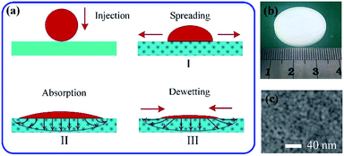
All nanoporous substrates in this work were fabricated through drying of aqueous dispersions of silica colloidal particles (Ludox SM-30) commercially available from Sigma-Aldrich. The radius of the silica particle is 5 nm, and the initial concentration is 30 wt%. The molar mass and density are 60.08 g mol−1 and 1.22 g mL−1 at 25 °C, respectively. A controlled volume of colloidal dispersions was injected into a Petri dish and left to evaporate from the free surface for 48 hours under a natural environment (T = 25 °C, RH = 30%). Water evaporation will concentrate the dispersion until the formation of a solid porous substrate with a thickness of about 5 mm, as shown in Fig. 1(b). The uniform surface morphology of the substrate for the experiments is shown in Fig. 1(c). The volume fraction of the particles in the porous media is denoted by 1 − φ with φ the void volume fraction. The values of φ can be measured and calculated from volumes of the substrate and all particles in the experiments (∼33%). The permeability k can be deduced from the Kozeny–Carman law based on the size of the nanoparticles, k = φ3a2/45(1 − φ)2.23Colloidal solution preparation
The suspensions of polystyrene (PS) particles were purchased from Duke Scientific Corporation (5200A). The original mass concentration is 10 wt% and its nominal density is 1.05 g cm−3. The monodisperse PS colloidal solutions used in the experiments were diluted to 0.5, 1, 1.5, 2 wt% with pure water. The size of the PS particle is 3 μm. Before experiments, the suspensions were ultrasonicated for 10 min to make the suspensions dispersing and mixing uniform.In situ observation
The droplet was generated through a micro-injector controlled by a computer and gently deposited on the nanoporous surface. Droplets spreading and patterns forming were captured in situ by a high-speed camera (AOS, TRI-VIT) at 200 fps, which was connected to a microscope (OLYMPUS, BX3M) from top-view. The spreading and imbibition of droplets were simultaneously observed by a CCD camera (Dataphysics, IDS) from side-view at 120 fps. The nanoporous substrate was placed on a motorized stage and was able to move in three directions. It was used for accurately adjusting the focal plane to capture two-dimensional (2D) flow field and particle aggregation parallel to the substrate plane. All experiments were performed at an environmental temperature of about 22 °C and relative humidity 35%.Results and discussion
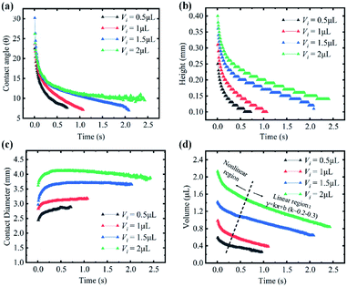
When a droplet was deposited on a porous substrate, it evolves three typical stages: spreading, absorption and dewetting, as shown in Fig. 1(a). The self-assembly of colloidal particles and the formation of the final patterns are the comprehensive results of these three stages. In the spreading stage I, the contact diameter of the droplet increases sharply while the contact angle and the droplet height decreases steeply, as shown in Fig. 2. The running contact radius is governed by Tanner's law. Droplet spreading would be prevented by the pinned contact line when the contact radius reached its maximum scale, which determined the size of the final patterns. This stage lasted several milliseconds. In stage II, the contact line does not move, and the contact angle decreased and finally reached to the static receding contact angle due to solvent absorption, as shown in Fig. 2(a) and (c). Then stage III started, the droplet began to shrink and dewetting occurred. Although it can be assumed that absorption plays a key role in stage II and stage III, the behaviour of solvent penetration and particles self-assembling in these two stages are not clear, which limits our understanding about the formation of the pattern. Therefore, the second and third stages are the main focuses of this work.Evaporation and absorption occur simultaneously for a colloidal sessile droplet resting on a porous substrate, which may influence the deposition patterns together. Thus, it is necessary to clarify the competitive effect of absorption and evaporation. Here, we have simplified the physical process and directly compared the time scales of solvent absorption and evaporation, which can be calculated through Darcy's law and quasi-steady evaporation, respectively. The Darcy's law can be expressed as
 | (1) |
 | (2) |
Therefore, the time for the droplet to penetrate in the porous medium, ta, can be expressed by using eqn (1) and (2)24
 | (3) |
 | (4) |
 | (5) |
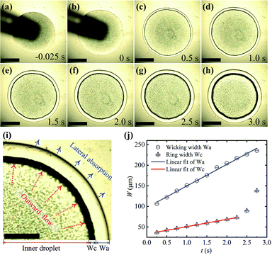
Fig. 3 shows the formation process of a ring-like stain and the wicking traces on the nanoporous substrate. The moment of the maximum contact radius of the droplet after spreading is defined as t = 0 s, as shown in Fig. 3(b). It can be observed that the ring pattern grows wider rapidly as with time, as shown in Fig. 3b–h, which indicates that most particles inside the droplet were carried towards the contact line under outward flow. The ring width (Wc) increased linearly with time when t < 2.5 s (Wc = 18t + 33), which followed by a rapid increase, as shown in the red line of Fig. 3(j). The change rate of the ring width could reflect the magnitude and trend of the outward flow, although this changing rate is less than the flow velocity for the multilayer structures of the ring. The outward flow was caused by lateral solvent absorption, whose traces can be seen in the outer regions of the black ring, as shown in Fig. 3(i). The relationship between the width of the lateral absorption trace (Wa) and times also seems to be a linear increase (Wa = 52t + 91), as shown in the blue line of Fig. 3(j). These two curves of Fig. 3(j) shown that the velocity of lateral absorption remains approximately the same over time, which induces the basically constant outward flow inside the droplet. The outward flow increases ultimately because there is no enough solvent to replenish the lateral absorption. As mentioned above, the effects of evaporation on the ring stain are so weak, although the micro-flow caused by lateral absorption was almost similar to the flow induced by the uneven evaporation flux.
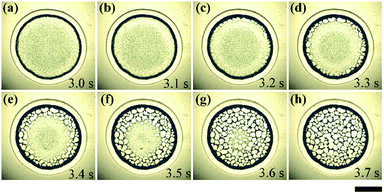
As with liquid penetrating into the nanoporous substrate, the droplet evolves into a thin liquid film, then the solvent inside the film was insufficient to replenish the lateral absorption. Therefore, the contact line started to slip and the liquid film dewetted by nucleation and growth of dry patches from the edge to the center, as shown in Fig. 4. All of these dry patches formed network structures inside the ring. This process lasted less than 1 second.
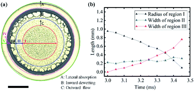
To further analyse the evolution and formation of the network pattern, a typical dynamic pattern was chosen and divided into five typical regions, as shown in Fig. 5(a). In region I, all particles remained stationary because they were confined between the liquid film and the solid surface. In region II, particles from the periphery of the region I (the dotted red line) move rapidly towards the region III under the outward flow caused by lateral absorption, it shows obvious radial streamlines in Fig. 5(a). The liquid film in region III was extremely unstable, and dewetting occurred from the edge of region III (the dark green line) towards the centre (the inward dewetting of Fig. 5(a)), i.e., the contact line shrank. If there were not enough particles distributing at this region, the liquid film would rupture at the particle-poor region and the dry patches formed. The inward expansion of the dry patches, together with the outward flow, made particles accumulate near the boundary of the patches (the blue line). Those particles would assemble into ordered structures under the capillary immersion forces. The competition of the inward expansion of dry patches and the outward motion of particles decide the final network structures. Region IV and V show the ring-like stain and the lateral absorption trace, respectively, which remains basically constant in this dewetting stage (stage III).
Fig. 5(b) shows the time evolution of the radius of the region I (the black line) and width of region II (blue line) and III (the red line). These curves reflect the formation rate of the network patterns. The average expanding rate of region III is about 1.7 mm s−1, which is approximately equal to the shrinkage rate of the region I (1.9 mm s−1). It suggests the network structures have a rapid but stable growth from the periphery toward the centre, thus the width of the region (II) keeps roughly unchanged, as shown in Fig. 5(b). The formation rate of the network patterns induced by absorption is much larger than that of evaporation,26 which further proves that evaporation is negligible.
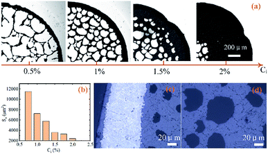
The morphologies of the final patterns on the nanoporous substrate can be controlled by changing the initial concentrations of the colloidal suspensions. As shown in Fig. 6(a), when the concentration increase from left to right (0.5, 1, 1.5, 2 wt%), the particle-free regions gradually become smaller and the network become denser. The average sizes of the voids (Sa) decreases with initial concentrations of colloidal suspensions (Ci), as shown in Fig. 6(b). The network pattern will transform into the submonolayer structure with voids as the concentration continues to increase. These voids concentrate in the centre and eventually diminish. The absorption-induced ring-like pattern has multilayer hexagonal close-packed (hcp) structures, as shown in Fig. 6(c). It forms submonolayer hcp structures inside the ring, as shown in Fig. 6(d). The particle size also affect the formation of the networks patterns. Based on the forces analysis of colloidal particles,26 the network patterns form more easily for larger particles because of the smaller frictional forces between the particle and the nanoporous substrate.
Conclusions
In this work, we have experimentally investigated the formation of the ordered ring and its inner network patterns based on a nanoporous substrate. Compared to absorption, evaporation was negligible for the formation of the pattern. We have shown that the ring structure was resulted from the outward flow caused by the lateral absorption. The evolution of the network pattern was further analysed, which indicates that the mutual competition between the inward dewetting and the outward flow determines rupture of the liquid film, expansion of the dry patches and redistribution of the colloidal particles, which eventually decide the inner network patterns. The capillary immersion forces dominate the self-assembly of particles and promote the ordered arrays of the structures.Conflicts of interest
There are no conflicts to declare.Acknowledgements
The authors gratefully acknowledge financial support from National Natural Science Foundation of China (Grant No. U1738118 and No. 11902321).Notes and references
- H. Elsayed, A. Chmielarz, M. Potoczek, T. Fey and P. Colombo, Addit. Manuf., 2019, 28, 365 CAS.
- Y. Wang, H. Guo, J. Chen, E. Sowade, Y. Wang, K. Liang, K. Marcus, R. R. Baumann and Z. Feng, ACS Appl. Mater. Interfaces, 2016, 8, 26112 CrossRef CAS PubMed.
- G. Wang, C. Hou and H. Wang, Flexible and Wearable Electronics for Smart Clothing, John Wiley & Sons, Weinheim, Germany, 2020 Search PubMed.
- R. D. Deegan, O. Bakajin, T. F. Dupont, G. Huber, S. R. Nagel and T. A. Witten, Nature, 1997, 389, 827 CrossRef CAS.
- H. Hu and R. G. Larson, J. Phys. Chem. B, 2006, 110, 7090 CrossRef CAS PubMed.
- Y. Li, Y. Sheng and H. Tsao, Langmuir, 2013, 29, 7802 CrossRef CAS PubMed.
- L. Bansal, P. Seth, B. Murugappan and S. Basu, Appl. Phys. Lett., 2018, 112, 211605 CrossRef.
- P. J. Yunker, T. Still, M. A. Lohr and A. J. Yodh, Nature, 2011, 476, 308 CrossRef CAS PubMed.
- D. Mampallil, J. Reboud, R. Wilson, D. Wylie, D. R. Klug and J. M. Cooper, Soft Matter, 2015, 11, 7207 RSC.
- N. Shahidzadeh, M. F. Schut, J. Desarnaud, M. Prat and D. Bonn, Sci. Rep., 2015, 5, 1 Search PubMed.
- S. Das, A. Dey, G. Reddy and D. D. Sarma, J. Phys. Chem. Lett., 2017, 8, 4704 CrossRef CAS PubMed.
- M. C. Lopes and E. Bonaccurso, Soft Matter, 2012, 8, 7875 RSC.
- T. Lim, J. Jeong, J. Chung and J. T. Chung, J. Mech. Sci. Technol., 2009, 23, 1788 CrossRef.
- W. Ristenpart, P. Kim, C. Domingues, J. Wan and H. A. Stone, Phys. Rev. Lett., 2007, 99, 234502 CrossRef CAS PubMed.
- A. Clarke, T. Blake, K. Carruthers and A. Woodward, Langmuir, 2002, 18, 2980 CrossRef CAS.
- S. H. Davis and L. M. Hocking, Phys. Fluids, 2000, 12, 1646 CrossRef CAS.
- S. H. Davis and L. M. Hocking, Phys. Fluids, 1999, 11, 48 CrossRef CAS.
- V. M. Starov, S. R. Kostvintsev, V. D. Sobolev, M. G. Velarde and S. A. Zhdanov, J. Colloid Interface Sci., 2002, 252, 397 CrossRef CAS PubMed.
- V. M. Starov, S. A. Zhdanov and M. G. Velarde, Langmuir, 2002, 18, 9744 CrossRef CAS.
- V. M. Starov, S. R. Kosvintsev, V. D. Sobolev, M. Velarde and S. J. J. o. c. Zhdanov, J. Colloid Interface Sci., 2002, 246, 372 CrossRef CAS PubMed.
- H. Haidara, B. Lebeau, C. Grzelakowski, L. Vonna, F. Biguenet and L. Vidal, Langmuir, 2008, 24, 4209 CrossRef CAS PubMed.
- C. K. Wemp and V. P. Carey, Langmuir, 2017, 33, 14513 CrossRef CAS PubMed.
- E. R. Dufresne, E. I. Corwin, N. A. Greenblatt, J. Ashmore, D. Y. Wang, A. D. Dinsmore, J. X. Cheng, X. S. Xie, J. W. Hutchinson and D. A. Weitz, Phys. Rev. Lett., 2003, 91, 224501 CrossRef CAS PubMed.
- Z. Liu, Y. Wang, F. J. Muzzio, G. Callegari and G. Drazer, Langmuir, 2017, 33, 56 CrossRef CAS PubMed.
- R. G. Larson, AIChE J., 2014, 60, 1538 CrossRef CAS.
- W. Li, D. Lan and Y. Wang, Phys. Rev. E, 2017, 95, 042607 CrossRef PubMed.
| This journal is © The Royal Society of Chemistry 2020 |

