 Open Access Article
Shampoo assisted aligning of carbon nanotubes toward strong, stiff and conductive fibers
Jiaojiao Wang†
ac,
Jingna Zhao† af,
Lin Qiu
 d,
Fengcheng Lid,
Changle Xuac,
Kunjie Wuaf,
Pengfei Wange,
Xiaohua Zhang
 *bf and
Qingwen Li*a
aDivision of Advanced Nano-Materials and Key Laboratory of Multifunctional Nanomaterials and Smart Systems, Suzhou Institute of Nano-Tech and Nano-Bionics, Chinese Academy of Sciences, Suzhou 215123, China. E-mail: qwli2007@sinano.ac.cn
bInnovation Center for Textile Science and Technology, Donghua University, Shanghai 201620, China. E-mail: zhangxh@dhu.edu.cn
cNano Science and Technology Institute, University of Science and Technology of China, Suzhou 215123, China
dSchool of Energy and Environmental Engineering, University of Science and Technology Beijing, Beijing 100083, China
eCAS Key Laboratory for Mechanical Behavior and Design of Materials, Department of Modern Mechanics, University of Science and Technology of China, Hefei 230027, China
fDivision of Nanomaterials, Suzhou Institute of Nano-Tech and Nano-Bionics, Chinese Academy of Sciences, Nanchang 330200, China
First published on 18th May 2020
Abstract
High alignment and densification of carbon nanotubes (CNTs) are of key importance for strengthening CNT fibers, whereas direct stretching has a very limited effect when CNTs are highly entangled. We report that by lubricating CNT surfaces with viscous alcohols, the relative motion between CNTs improves because of the reduced sliding energy barrier; thus non-stretched regions are effectively eliminated. Owing to the very efficient optimization of the assembled structure, the stretched CNT fibers exhibited an average tensile strength of 2.33 GPa (1.82 N per tex) and modulus of 70.1 GPa (54.8 N per tex). Other fundamental properties, such as electrical and thermal conductivities, were also remarkably improved. Such a strategy can be readily used for manufacturing high-performance CNT assemblies and composites.
Introduction
Carbon nanotube (CNT) fibers, assembled structures of millions of interlaced CNTs, have shown excellent mechanical, electrical, and thermal properties, as summarized in many recent reviews.1–7 Compared to individual CNTs, whose strength and modulus reach 100 GPa and 1 TPa,8 the mechanical properties of CNT fibers still remain poorer (so far, increasing the strength to 4–5 GPa remains very difficult), because of imperfect assembly in terms of poor CNT alignment, loose densification, and weak intertube interactions.6 Recently, Bai et al.9 assembled tens of individual CNTs into a long and straight bundle and obtained a maximum strength of 80 GPa (43 GPa for the entire cross-sectional area). Zhao et al.10 reported that CNT fibers with a straight assembly—CNTs aligned and parallel to the fiber axis—can maintain a nearly unchanged tensile property with increasing fiber size. These studies strongly show the advantages of tube straightness.To date, solution spinning, array (forest) spinning, and spinning from as-grown CNT aerogels are the three principal preparation methods for CNT fibers.3,10 According to a comparison study between the forest- and aerogel-spun CNT fibers,10 aligning CNTs with the latter method is difficult because of the strong CNT entanglement that often causes stress localization at CNT connections and hinders the load transfer inside the fiber assembly. Simultaneously, there are numerous assembly flaws arising from the random CNT orientation. As a result, the aerogel-based CNT fiber does not exhibit a modulus and strength comparable to those of carbon fibers,11–13 and only a few short samples11 and roller-pressed narrow strips14,15 have reached a strength of over 9 GPa in the past decade. Improving the orientation of CNT (alignment and straightness describe the orientation from different perspectives10) is one of the most efficient strategies for strengthening CNT fibers.6,7 Stretching/drawing16 and twisting17,18 make CNTs more orderly and dense, yet the strengthening results are far less than expected. Polymer infiltration is another successful strategy because of enhanced adhesion19–22 and intertube friction23 between CNTs. Wang24 and Liu et al.25 recently, attempted to use polymer molecules to mobilize and align CNTs and to reach a certain straight CNT assembly. Therefore, it is expected that the highly entangled CNT assembly can be converted into a straight structure by improving the stretching efficiency. Clearly, the key issue is the mobilization of the entangled CNTs.
Here, we introduce an efficient method to optimize CNT assemblies containing entangled tubes, based on the lubrication of CNT surfaces. Highly viscous alcohols, among which glycerol is better, make CNT connections slippery to eliminate the non-stretching caused by strong connections. This results in high CNT alignment and packing density and greatly improves the tensile strength, Young's modulus, and electrical and thermal conductivities. This may also encourage the development of fabrication techniques for CNT composite structures and composites.
Experimental section
The CNT fibers were prepared by the iCVD method.13,14,26,27 A mixture containing ethyl alcohol as the carbon source, ferrocene as the catalyst precursor, and thiophene as a promoter were injected into the furnace with the aid of Ar/H2 gas flow. At the reaction temperature of 1300 °C, entangled CNTs were continuously grown out and collected by a rotating winder. After immersion in a water bath, the CNTs were converted into narrow ribbons and collected. In order to increase the packing density, the CNT ribbons were finally twisted into fibers with a twist angle of ∼20°.The CNT fibers were then soaked in ethylene glycol or glycerol for at least 2 h at a temperature of 120 °C to reduce the viscosity of the solvents. After solvent impregnation, hot stretching was performed for the fibers with an MTS E44 universal testing machine (UTM, MTS Systems Corp., Eden Prairie, USA) equipped with an environmental chamber. The fiber sample was fixed on two clamps, which were initially 10 cm apart. Stretching was conducted at 120 °C at a rate of 5 × 10⁻⁵ s−1. At every one % increment of tensile strain, the stretching was halted to relax the fiber structure.17 During stretching, glycol or glycerol was dipped onto the CNT fiber to maintain the wet conditions. After the stretching, the chamber temperature was increased to 150 °C for 4 h to dry the solvent-impregnated CNT fibers.
The tensile properties were obtained with an Instron 3365 UTM (Instron Corp., Norwood, USA) with a load sensor of 10 N. CNT fibers were fixed to a paper template with a gauge length of 6 mm using cyanoacrylate glue (instant adhesive). The tensile rate was 1 mm min−1. As a common treatment, engineering stress and strain were used and calculated based on the original cross-sectional area and fiber length (gauge length). The fiber diameter was measured with an optical microscope, and the fiber mass was obtained with a high-precision analytical balance (XP2U, Mettler-Toledo LLC, USA), with a total fiber length of 30–50 cm (the high precision of 0.1 μg of the balance permits accurate measurements even for a CNT fiber with a length of 5 cm. However, we usually measure a group of short fibers together to avoid misevaluation).
The surface morphology and microstructure of the CNT fibers were observed with a hot field emission scanning electron microscope (SEM, Quanta 400 FEG, FEI, Hillsboro, USA) and a cold field emission SEM (Hitachi S4800, Tokyo, Japan). The degree of CNT alignment was characterized by polarized Raman spectroscopy (LabRAM HR, HORIBA Jobin Yvon, Paris, France) with a 532 nm laser.28 The angle was set to that between the fiber axis and polarization axis of the incident laser beam. The electrical conductivity was obtained by using the current–voltage relationship with a programmable power supply (Keithley 2200-60-2, Tektronix Inc., Beaverton, USA). The thermal conductivity was measured via a self-heating 3ω method.29 As we recently reported, the intrinsic (true) conductivity is represented well by the apparent conductivity obtained with a short fiber length (1 mm was used in this study) because the length square dependent heat radiation can be suspended.
Results and discussion
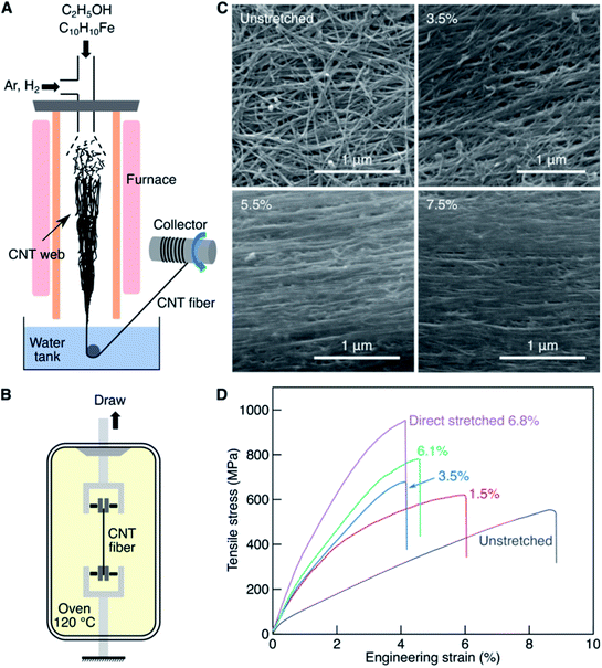
The CNT fibers used in this study were obtained via injection chemical vapor deposition (iCVD, or floating catalyst CVD)13,26 as schematically shown in Fig. 1A. Direct stretching was performed on the CNT fibers (Fig. 1B), with a very low stretching rate of 10−5 s−1 (fast stretching can cause the fiber to break much earlier due to insufficient stress relaxation30). Gradually increasing the stretching ratio to 3.5%, 5.5%, and 7.5% (the elongation with respect to the original length) increased the overall alignment of the CNTs as shown in the SEM images in Fig. 1C. The porosity of the fiber decreased as reflected by the increase in mass density from 0.81 g cm−3 for the unstretched fiber to 1.28 g cm−3 after stretching by 7.5%. The increase in mass density was primarily caused by the decrease in the fiber diameter from 37 to 30 μm.The improved CNT alignment and densification greatly strengthened the stretched CNT fibers (Fig. 1D). The as-produced CNT fiber showed a tensile strength of 556 MPa and a strain at break of 8.8%. As the stretching level increased, the fiber became stronger and more brittle. For example, after stretching by 6.8%, the fiber strength increased to 953 MPa, and the strain at break decreased to 4.1%. As a result, Young's modulus also increased from 7.6 GPa (unstretched) to 39.5 GPa (direct stretched by 6.8%).
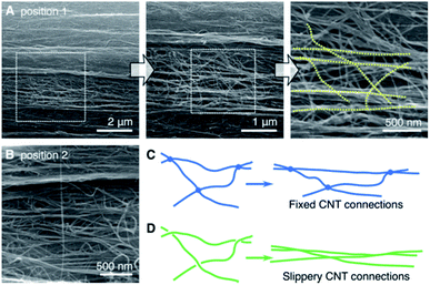
The strengthening results by direct stretching are not satisfying, as the final strength is still low (obtaining a strength of over 3 GPa for forest-spun fibers is still very difficult7,10). Therefore, to determine the reason from a structural perspective, the microstructures were characterized with SEM for the direct stretched samples (Fig. 2). After stretching by 7.5%, although the overall CNT alignment was remarkably improved, many small regions remained unstretched, retaining the entangled network (Fig. 2A). Fig. 2B provides another example to illustrate the ubiquity of entanglement. The two principal reasons hindering the stretching effect are: (i) the nonuniform CNT distribution where the most densified CNTs are stretched first and carry most of the applied stress, and (ii) rich CNT connections that cause only a few edges of a cell in the CNT network be stretched while other edges are unstretched. The former issue can be overcome by precise CNT growth and the collection method, while the latter is the fundamental problem of an entangled network. During the CVD growth, CNTs are attracted with each other by van der Waals interactions to form rich CNT connections, and the entanglement further strengthen or fix the CNT connections, providing additional energy barrier to separate the CNTs from the connections.
Fig. 2C schematically shows a typical stretching process on a triangular cell with fixed CNT connections. Upon stretching, only the horizontal CNT straightens; the other two CNTs cannot be straight as their total length is longer than the horizontal one. The dotted lines in Fig. 2A show that only a few CNTs were stretched while multiple others remained entangled, confirming the schematic in Fig. 2C. The fixed CNT connections are primarily caused by entanglement rather than by intertube interaction; this is reminiscent of tangled and/or knotted hair.
Life experiences with the use of anti-frizz shampoo and hair conditioner to detangle hair and the aversion to tangling of smooth and healthy hair revealed the solution to the aforementioned problem. As shown in Fig. 2D, when the connections are lubricated, most CNTs can be straightened by sliding. Interestingly, two recent studies have shown that thermoplastic polymers such as ultrahigh molecular weight polyethylene and polyvinyl alcohol can mobilize and align CNTs upon stretching.24,25 This is a way to overcome CNT entanglement by providing more stress transfer to the CNTs via the polymers. However, the high aligning of pure CNT assemblies remains more important. Considering that many polar solvents can change the intertube interactions by providing polarity-induced attraction between solvent molecules and CNTs,31 it should be possible to “soften” the CNT connections and increase the slipperiness to slide the CNTs apart and thus create the mechanism shown in Fig. 2D.
Highly polar and viscous ethylene glycol and glycerol (interestingly, a component of shampoo) were used to soften the CNT connections; the dipole moments of the ethylene glycol and glycerol are 2.2 D and 2.6 D, and the viscosities 16 and 945 cP at 25 °C, respectively. The similar dipole moments allow a sufficient driving force transfer from the solvent molecules to CNTs, and the high viscosity does not cause the CNT connections to slip. Therefore, hot stretching (Fig. 1B) was applied to decrease the viscosity, which is <2 and 7.8 cP at 120 °C for glycol and glycerol, respectively. In the experiment, 20°-twisted CNT fibers were soaked inside glycol and glycerol at 120 °C and gently hot stretched with a tensile tester with a low tension rate of 5 × 10⁻⁵ s−1 at 120 °C. The stretching was halted at one % increments of tensile strain to relax the fiber structure until the strain reached 6–7%. Finally, the stretched samples were dried in a vacuum at 150 °C for 4 h (such temperature causes efficient evaporation of glycerol, and the vacuum accelerates this process32,33).
Our treatment differed substantially from a recent study34 in which strong acid was used to induce CNT-detangling based on the repulsive interaction between charged CNTs. In that situation, efficient aligning was also achieved with an excellent strengthening result. Unfortunately, although many solvents can lubricate CNTs, most of them do not show a good aligning ability for CNTs because they lack the appropriate polarity or viscosity. For instance, acetone, N-methyl-2-pyrrolidone, and dimethylformamide, were found to share a densification ability similar to that of ethanol, but neither of them showed a stretching-and-aligning ability comparable to that of glycol.
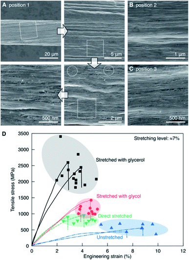
Fig. 3A shows the morphology of a CNT fiber stretched with glycerol impregnation. Overall, the stretching induced wrinkles in fiber surface, and the CNTs became denser. Zooming in, the microstructures became much clearer; nearly all the CNTs were parallel to the stretching direction. Small regions of incomplete stretching remained, as marked by dotted circles; however, these were far fewer than in Fig. 2. Two other positions are shown in Fig. 3B and C, where the CNTs were also highly aligned and densified.
Fig. 3D compares the stress–strain curves for CNT fibers stretched by various methods. The unstretched fibers were not strong at ≈700 MPa because of the strong CNT entanglement. By increasing the degree of alignment with direct, glycol-assisted, and glycerol-assisted stretching, the stress–strain curves were gradually lifted. The direct and glycol-assisted stretching increased Young's modulus to approximately 35 GPa, whereas polar glycol further densified the CNTs,31 resulting in a better strengthening result; the tensile strength was approximately 300–500 MPa higher than the direct stretching. Glycerol-assisted stretching showed the highest strengthening results, with average and maximum tensile strengths of 2.33 and 3.44 GPa, respectively. The average and maximum values for Young's modulus were 70.1 and 86.0 GPa, respectively. By considering the mass density of 1.28 g cm−3, the specific strength and modulus increased to 1.82 and 54.8 N per tex, respectively.
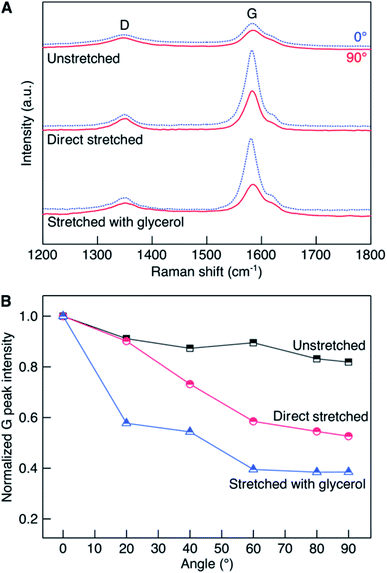
The improved CNT alignment was the key to the strengthening effect. To evaluate the alignment, polarized Raman spectroscopy was performed.28 As shown in Fig. 4, the G band intensity gradually decreased with increasing angle between the polarized laser and the fiber axis. The anisotropy between the G band intensity at 0° and 90° was used to describe the different CNT alignment in various fibers. This ratio was 1.22, 1.97, and 2.62 for the unstretched, direct stretched, and glycerol-stretched fibers, respectively (Fig. 4A). Fig. 4B shows the normalized G band intensities for the three samples as a function of the polarization angle and normalized with respect to the value at 0°. The lowest normalized G peak intensity at 90° was nearly comparable to that of a highly aligned CNT film,35 indicating that the alignment was remarkably improved. Clearly, the glycerol-assisted stretching showed the most efficient stretching ability.
After the new stretching treatment, the CNTs became highly aligned and tightly packed, with remarkably reduced assembly flaws. Thus, the conducting properties should also be improved. Fig. 5 compares Young's modulus, electrical conductivity, and thermal conductivity between the unstretched and glycerol-stretched CNT fibers. The stretching increased the modulus from 8.4 to 70.1 GPa, electrical conductivity from 1.8 to 3.3 × 10⁵ S m−1, and thermal conductivity from 45.7 to 98.1 W m−1 K−1. The enhancement in the two conductivities was larger when compared to the strategy using guest nanoparticles or aromatic polymers,29,35 showing the advantages of the improved CNT alignment.
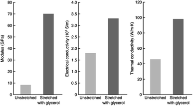 | ||
| Fig. 5 Young's modulus, electrical conductivity, and thermal conductivity of the unstretched and glycerol-stretched CNT fibers. | ||
Conclusion
In summary, improving the alignment of CNTs is essential for high-performance CNT fibers and films. Inspired by the life experiences of hair detangling, the weakening of CNT connections in their entangled assemblies is shown to be an efficient strategy to realize full alignment. By using glycerol and its high polarity as a weakening agent, the entangled CNTs were fully stretched into a highly aligned assembly. The fiber strength, modulus, and electrical and thermal conductivities were all remarkably improved. Such aligning strategies can help achieve high-performance CNT composite materials.Conflicts of interest
There are no conflicts to declare.Acknowledgements
The authors thank the financial support from the National Natural Science Foundation of China (51862036, 21773293, U1710122, 11872361), Outstanding Youth Foundation of Jiangxi Province (2018ACB21023), Key Research and Development Project of Jiangxi Province (20192BBE50031), Science and Technology Project of Nanchang (2017-SJSYS-008), and Suzhou Science and Technology Plan Projects (SYG201831).Notes and references
- W. Lu, M. Zu, J. H. Byun, B. S. Kim and T.-W. Chou, Adv. Mater., 2012, 24, 1805 CrossRef CAS PubMed.
- M. Miao, Particuology, 2013, 11, 378 CrossRef CAS.
- J. Di, X. Zhang, Z. Yong, Y. Zhang, D. Li, R. Li and Q. Li, Adv. Mater., 2016, 28, 10529 CrossRef CAS PubMed.
- D. Janas and K.-K. Koziol, Nanoscale, 2016, 8, 19475 RSC.
- M. D. Yadav, K. Dasgupta, A. W. Patwardhan and J. B. Joshi, Ind. Eng. Chem. Res., 2017, 56, 12407 CrossRef CAS.
- Y. Jung, Y. S. Cho, J. W. Lee, J. Y. Oh and C. R. Park, Compos. Sci. Technol., 2018, 166, 95 CrossRef CAS.
- X. Zhang, W. Lu, G. Zhou and Q. Li, Adv. Mater., 2020, 32, 1902028 CrossRef CAS PubMed.
- R. S. Ruoff, D. Qian and W. K. Liu, C. R. Physique, 2003, 4, 993 CrossRef CAS.
- Y. Bai, R. Zhang, X. Ye, Z. Zhu, H. Xie, B. Shen, D. Cai, B. Liu, C. Zhang, Z. Jia, S. Zhang, X. Li and F. Wei, Nat. Nanotechnol., 2018, 13, 589 CrossRef CAS PubMed.
- J. Zhao, X. Zhang, Y. Huang, J. Zou, T. Liu, N. Liang, F. Yu, Z. Pan, Y. Zhu, M. Miao and Q. Li, Mater. Des., 2018, 146, 20 CrossRef CAS.
- K. Koziol, J. Vilatela, A. Moisala, M. Motta, P. Cunniff, M. Sennett and A. Windle, Science, 2007, 318, 1892 CrossRef CAS PubMed.
- S. Boncel, R. M. Sundaram, A. H. Windle and K. K. K. Koziol, ACS Nano, 2011, 5, 9339 CrossRef CAS PubMed.
- J. Zou, X. Zhang, J. Zhao, C. Lei, Y. Zhao, Y. Zhu and Q. Li, Compos. Sci. Technol., 2016, 135, 123 CrossRef CAS.
- J. N. Wang, X. G. Luo, T. Wu and Y. Chen, Nat. Commun., 2014, 5, 3848 CrossRef CAS PubMed.
- W. Xu, Y. Chen, H. Zhan and J. N. Wang, Nano Lett., 2016, 16, 946 CrossRef CAS PubMed.
- Y. Yue, K. Liu, M. Li and X. Hu, Carbon, 2014, 77, 973 CrossRef CAS.
- J. Zhao, X. Zhang, J. Di, G. Xu, X. Yang, X. Liu, Z. Yong, M. Chen and Q. Li, Small, 2010, 6, 2612 CrossRef CAS PubMed.
- S. Fang, M. Zhang, A. A. Zakhidov and R. H. Baughman, J. Phys.: Condens. Matter, 2010, 22, 334221 CrossRef PubMed.
- K. Liu, Y. Sun, X. Lin, R. Zhou, J. Wang, S. Fan and K. Jiang, ACS Nano, 2010, 4, 5827 CrossRef CAS PubMed.
- S. Ryu, Y. Lee, J.-W. Hwang, S. Hong, C. Kim, T. G. Park, H. Lee and S. H. Hong, Adv. Mater., 2011, 23, 1971 CrossRef CAS PubMed.
- S. Ryu, J. B. Chou, K. Lee, D. Lee, S. H. Hong, R. Zhao, H. Lee and S.-g. Kim, Adv. Mater., 2015, 27, 3250 CrossRef CAS PubMed.
- A. M. Beese, S. Sarkar, A. Nair, M. Naraghi, Z. An, A. Moravsky, R. O. Loutfy, M. J. Buehler, S. T. Nguyen and H. D. Espinosa, ACS Nano, 2013, 7, 3434 CrossRef CAS PubMed.
- X. Zhang, Mater. Res. Express, 2018, 5, 015007 CrossRef.
- J. Wang, M. Miao, Z. Wang, W. Humphries and Q. Gu, Carbon, 2013, 57, 217 CrossRef CAS.
- J. Liu, W. Gong, Y. Yao, Q. Li, J. Jiang, Y. Wang, G. Zhou, S. Qu and W. Lu, Compos. Sci. Technol., 2018, 164, 290 CrossRef CAS.
- Y.-L. Li, I. A. Kinloch and A. H. Windle, Science, 2004, 304, 276 CrossRef CAS PubMed.
- W. Li, J. Zhao, Y. Xue, X. Ren, X. Zhang and Q. Li, Carbon, 2019, 145, 266 CrossRef CAS.
- W. Liu, X. Zhang, G. Xu, P. D. Bradford, X. Wang, H. Zhao, Y. Zhang, Q. Jia, F. G. Yuan, Q. Li, Y. Qiu and Y. Zhu, Carbon, 2011, 49, 4786 CrossRef CAS.
- L. Qiu, P. Guo, X. Yang, Y. Ouyang, Y. Feng, X. Zhang, J. Zhao, X. Zhang and Q. Li, Carbon, 2019, 145, 650 CrossRef CAS.
- Y. Zhang, L. Zheng, G. Sun, Z. Zhan and K. Liao, Carbon, 2012, 50, 2887 CrossRef CAS.
- S. Li, X. Zhang, J. Zhao, F. Meng, G. Xu, Z. Yong, J. Jia, Z. Zhang and Q. Li, Compos. Sci. Technol., 2012, 72, 1402 CrossRef CAS.
- D. F. Stedman, Trans. Faraday Soc., 1928, 24, 289 RSC.
- D. J. Trevoy, Ind. Eng. Chem., 1953, 45, 2366 CrossRef CAS.
- J. Lee, D. M. Lee, Y. Jung, J. Park, H. S. Lee, Y. Kim, C. Park, H. Jeong and S. Kim, Nat. Commun., 2019, 10, 2962 CrossRef PubMed.
- J. Zhao, Q. Li, B. Gao, X. Wang, J. Zou, S. Cong, X. Zhang, Z. Pan and Q. Li, Carbon, 2016, 101, 114 CrossRef CAS.
Footnote |
| † J. W. and J. Z. contributed equally to this work. |
| This journal is © The Royal Society of Chemistry 2020 |

