 Open Access Article
S-doped porous carbon anode with superior capacity for high-performance sodium storage†
Yaru Liang ,
Rutie Liu* and
Xiang Xiong*
State Key Laboratory of Powder Metallurgy, Central South University, Lushan South Road, Changsha, 410083, P. R. China. E-mail: xiongx@csu.edu.cn
First published on 12th June 2020
Abstract
Heterogeneous carbon-based materials with high porosity are attracting increased attention for energy storage due to their enhanced capacity and rate performance. Herein, we report a sulfur-doped porous carbon material, which is achieved by spray-drying and subsequent sulfuration. The porous structure can provide vast diffusive tunnels for the fast access of electrolytes and sodium ions. Also, the S–C bond increases the electrical conductivity of the carbon frameworks and offers excessive reaction sites for sodium-ion storage. The elaborated carbon architecture enables a high capacity of 370 mA h g−1 at 0.5 A g−1 and provides an excellent rate performance for long-term cycling (197 mA h g−1 at 2.0 A g−1 for 650 cycles). Considering the scalable and facile spray-pyrolysis preparation route, this material is expected to serve as a low-cost and environmentally friendly anode for practical sodium-ion batteries.
Introduction
Due to the rapid consumption of lithium resources, the commercial production of lithium-ion batteries (LIBs) is seriously restricted by the increasing price of lithium resources.1 Sodium-ion batteries (SIBs), with abundant reserves of raw materials and reasonable energy density, are considered as one of the most promising alternatives to LIBs.2 Unfortunately, the radius of sodium-ions is 55% larger than that of lithium-ions, which makes it difficult to reversibly insert into electrode materials.3 Only a few materials for lithium-ion batteries are suitable for accommodating sodium-ions. Therefore, the study on high-performance and low-cost sodium-ion battery electrodes materials is one of the most important directions for the development of sodium-ion batteries. So far, including carbonaceous materials,4 metals/alloys,5 metal oxides,6 a large number of materials have been studied as anode materials for SIBs. Among them, carbon-based materials are the most potential anode materials for the commercial application of sodium-ion batteries due to their low potential (vs. Na+), high conductivity, good cycle stability, and low cost.7Porous structure designing and element doping are used to solve the problem of high irreversibility and capacity loss of hard carbon materials.8 Various technologies, including hydrothermal carbonization, emulsion templating, ice templating, were studied to synthesize the porous carbon.9 However, most of them often need harsh reaction conditions or high costs.7 Therefore, as a facile and low-cost method for synthesize of the porous carbon, spray-drying is highly desirable for large-scale preparation. In this paper, S-doped carbon (SPC) materials were introduced by a simple spray-drying method and subsequent carbonization and sulfurization. The porous structure can promote mass transport and short diffusion distance, while the S-doping could improve the electrical conductivity of carbon by generating extrinsic defects. The pseudo-capacitance mechanism delivers a fast adsorption/desorption process, which is beneficial to the Na+ storage. Thus, the material shows superior sodium storage ability, excellent rate, and long-cycle performance.
Experimental
Synthesis of SPC
The lab-scale spray drying system (Fig. S1†) was used to prepare the styrene butadiene rubber (SBR) powders. The SBR latex (solid content 48%) for spray drying was bought from Nippon A&l Inc. The temperatures at the outlet of the spray dryer were fixed at 120 °C and 180 °C, respectively. The dried precursor was ground with sulfur in an agate mortar and sealed in quartz tube, then calcined at 650 °C for 2 hours to obtain the final samples.Characterization
X-ray powder diffractometer (XRD, Bruker AXS D8 Advance), and Raman spectrometer (Renishaw, in Via-reflex) were used to characterize the phase structure, elemental constituents and surface elemental state of the products. Field emission scanning electron microscopy (FESEM; HITACHI-SU8200) and transmission electron microscopy (TEM; Jeol-2100F) were employed to confirm the size, surface morphology, and interior structure of the samples.Electrochemical measurements
The electrochemical performances of the obtained samples were tested in half coin cells (CR2032). The active material (70 wt%), the conductive agent (Super P, 20 wt%), and the binder (PVDF, poly(vinylidene fluoride), 10 wt%) were dissolved in N,N-dimethylpyrrolidone (NMP) to form a uniform slurry. The slurry was coated on a Cu foil and dried at 120 °C for 12 h. The electrolyte is made up with NaClO4 (1 M), propylene carbonate and ethylene carbonate (1![[thin space (1/6-em)]](https://www.rsc.org/images/entities/char_2009.gif) :
:![[thin space (1/6-em)]](https://www.rsc.org/images/entities/char_2009.gif) 1 volume%), and fluoroethylene carbonate (5 wt%). The half coin cells were assembled in a glovebox filled with Ar and the water and oxygen concentration less than 0.1 ppm. The cycling test were performed on a LAND battery testing system at room temperature with the voltage ranges between 0.01 and 3 V. The CV and EIS were performed on an Autolab modular electrochemical system (Autolab PGSTAT302N). CV was conducted in the potential window of 0.01–3.0 V, and EIS was conducted over a frequency range of 100 kHz to 0.01 Hz after cycled for 1 round at 500 mA g−1.
1 volume%), and fluoroethylene carbonate (5 wt%). The half coin cells were assembled in a glovebox filled with Ar and the water and oxygen concentration less than 0.1 ppm. The cycling test were performed on a LAND battery testing system at room temperature with the voltage ranges between 0.01 and 3 V. The CV and EIS were performed on an Autolab modular electrochemical system (Autolab PGSTAT302N). CV was conducted in the potential window of 0.01–3.0 V, and EIS was conducted over a frequency range of 100 kHz to 0.01 Hz after cycled for 1 round at 500 mA g−1.
Results and discussion
By collecting the SBR, S-doped carbon materials with porous structure were prepared after subsequent carbonization and sulfurization (Fig. 1a). For comparison, samples dried at 120 °C and 180 °C were prepared and named as SPC-120 and SPC-180, respectively. The crystalline structure of the samples was characterized by XRD. As can be seen in Fig. 1b, for both SPC-120 and SPC-180, the carbon does not show a sharp diffraction peak. All samples exhibit disordered carbon structure with broad peaks of (002) planes at around 2θ = 24.1°, which is significantly shifted to lower angles compared with graphite. According to Bragg's equation, the interlayer distance (d002) of the SPC-180 is calculated as 3.90 Å, which is much larger than that of graphite (3.35 Å). Because the radius of S (102 pm) is larger than that of C (77 pm), S-doping should be the main reason for the enlarged d-spacing in the samples. The larger interlayer distance will be more suitable for the insertion of sodium-ions, and consequently contributes a higher capacity.10 Besides, the reflection of sulphur was only observed in SPC-120, which indicated that there were S particles remained in the SPC-120 after heat treatment. Meanwhile, from the XRD pattern of SPC-180, there is no peak can be ascribed to the polymer or sublimed sulphur. The S is evenly distributed in SPC-180, which was further confirmed by the EDS (Energy-dispersive X-ray spectroscopy) mapping of SPC-180 (Fig. S2†). Raman spectroscopy was further applied to study the structure of these carbon materials, and the results are shown in Fig. 1c. Both samples demonstrate two broad peaks corresponding to the D band (1345 cm−1) and the G band (1590 cm−1), respectively. The graphitization degree of carbon can be obtained by calculating the integral strength ratio (ID/IG).11 The strength ratio of D- and G-band (ID/IG) of SPC-180 and SPC-120 are 1.09 and 1.75, respectively. Generally, the smaller the intensity ratio of the D band to the G band (ID/IG), the better the graphitization and well-ordered structure is. Thus, the partial graphitization degree in these samples is beneficial to improving the electrical conductivity.12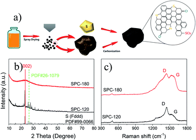 | ||
| Fig. 1 (a) Illustration of the preparing process of S-doped porous carbon material, and the (b) XRD patterns and (c) Raman spectroscopy of samples as-prepared. | ||
The structure and morphology of as-prepared SPC-120 and SPC-180 were analyzed by scanning electron microscopy (SEM) and transmission electron microscope (TEM). It can be seen from the SEM figures that both the SPC-120 (Fig. 2a) and SPC-180 (Fig. 2b) mainly consist of a spherical structure with a size of 2–10 μm. In the high-resolution SEM images of SPC-180 (Fig. 2c), porous with diameter of about 10–50 nm are detected. These pores were also detected from the TEM (Fig. 2e). In contrast, the SPC-120 shows no obvious porous in SEM and TEM image (Fig. 2d). The pores structure can provide a large number of channels for the sulphur vapour penetrating the interior of the carbon sphere. Besides, in the HRTEM of SPC-180 (Fig. 2f), lattice fringes with the spacing of 0.39 nm were observed. It indicates that the spacing lattice fringes were expanded after the doping of sulphur. This is corresponding with the results from the XRD patterns.
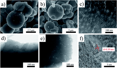 | ||
| Fig. 2 The SEM images of sample (a) SPC-120 and (b) SPC-180, (c) the SEM image of SPC-180 with higher resolution, the TEM images of (d) SPC-120 and (e) SPC-180, and (f) the HRTEM image of SPC-180. | ||
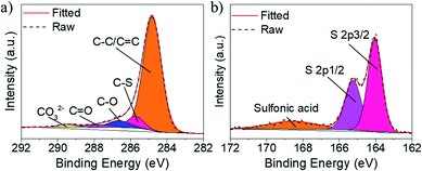
XPS measurements were carried out to investigate the surface element composition and chemical state of the samples. As shown in Fig. 3a and S3,† the XPS survey spectra confirm the existence of C, O and S in SPC-180. For the deconvolution of the XPS C 1s spectrum of SPC-180 (Fig. 3a), two fitted peaks at 284.8, 285.7 eV binding energy can be assigned to C–C and C–S bond vibration,13 while the fitted peaks at binding energies of 286.6, 287.7 and 289.5 eV should be attributed to the vibration of C–O, C![[double bond, length as m-dash]](https://www.rsc.org/images/entities/char_e001.gif) O and COO−, respectively.14 For the deconvolution of the XPS S 2p spectrum of SPC-180 (Fig. 3b), the fitted peaks at binding energy of 165.2 and 164.0 eV is related to the S 2p1/2 and S 2p3/2 of elemental S and the fitted peak at 168.5 eV should correspond to the Sulfonic acid configuration.15 The deconvolutions of the C 1s, and S 2p spectra of SPC-120 (Fig. S3c and d†) are similar to those of SPC-180.
O and COO−, respectively.14 For the deconvolution of the XPS S 2p spectrum of SPC-180 (Fig. 3b), the fitted peaks at binding energy of 165.2 and 164.0 eV is related to the S 2p1/2 and S 2p3/2 of elemental S and the fitted peak at 168.5 eV should correspond to the Sulfonic acid configuration.15 The deconvolutions of the C 1s, and S 2p spectra of SPC-120 (Fig. S3c and d†) are similar to those of SPC-180.
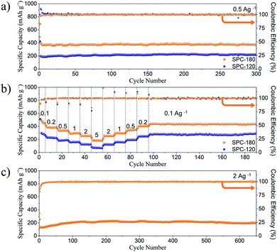
The cyclic performances of SPC-120 and SPC-180 at the current density of 0.5 A g−1 are shown in Fig. 4a and S4,† respectively. For SPC-120 and SPC-180, the discharge/charge capacity of the first cycle is 424/178 and 691/407 mA h g−1, respectively. The discharge plateau below 0.3 V for the initial cycle could be attributed to the irreversible decomposition of the electrolyte, the formation of solid-electrolyte interphase (SEI) layer, and Na+ ion intercalation into graphitic nanodomains and nanovoids.16 Therefore, the capacity retention rates of the two samples are 42% and 59% respectively. Although both the two electrodes show relatively low initial coulombic efficiencies due to the decomposition of electrolyte, the coulombic efficiency quickly reaches nearly 100% after several cycles, indicating their good structure stability. After 300 cycles, the reversible specific discharge capacity of SPC-180 remains at 370 mA h g−1, which is significantly higher than that of the SPC-120 electrode (221 mA h g−1). Besides, both the two samples have low capacity decay rate and stable coulomb efficiency of about 100%. The reversible capacities of SPC-180 are much higher than that of SPC-120 and other reported hard carbon.17 It indicating that the S doping and porously structure should be responsible for the performance. The porous structure can enrich the sulphur doping and shorten the ion diffusion distance, and the doped S could not only enhance the electrical conductivity of carbon, but also provide excess reaction sites for sodium-ion storage. The rate performance of SPC-120 and SPC-180 were tested at current densities ranged from 0.1 to 5 A g−1. As shown in Fig. 4b, the SPC-180 electrode not only has excellent sodium storage performance at room temperature, but also better rate performance than SPC-120. The specific discharge capacities of the SPC-180 were 446, 387, 335, 297, 254 and 185 mA h g−1 at current densities of 0.1, 0.2, 0.5, 1, 2 and 5 A h g−1, respectively. When the current was returned to the initial value, the specific capacity could be almost fully recovered, indicating that the material had excellent rate capability. Meanwhile, the discharge capacity of SPC-120 is only 270, 223, 190, 159, 124 and 67 mA h g−1 at current densities of 0.1, 0.2, 0.5, 1, 2 and 5 A h g−1, respectively. Moreover, the SPC-180 electrode exhibited excellent stability even at a high current density of 2 A g−1. After 650 cycles, it could still maintain a high capacity of 197 mA h g−1 (Fig. 4c). The excellent rate performance of the SPC-180 can be attributed to the porous structure, which can shorten diffusion distance of Na+ ions and electrons.18 The electrochemical performance of SPC-180 electrode is better than most of the reported carbon-based electrodes. The comparative results are listed in Table S1.†
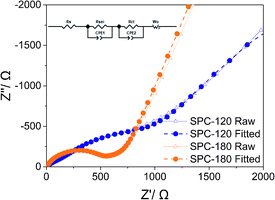
As shown in Fig. 5, because of the uniform distribution of S, the semicircle in Nyquist plots for the SPC-180 electrode after the first cycle represents charge transfer resistance. An additional semicircle in the middle frequency region of the Nyquist plot appears, indicating an inactive SEI layer was formed and coated onto the surface of SPC-120 after the first cycle.19 The Rct values calculated from the fitting results were 368 and 797 Ω for SPC-180 and SPC-120, respectively. Therefore, the Warburg impedance of SPC-180 electrode is smaller than that of SPC-120, which is beneficial to the charge transfer and the Na-ion storage properties.20
Pseudocapacitive Na+ storage based on the fast absorption/desorption kinetics can realize the high rate capability. Herein, the sodium-ion storage kinetic of the SPC-180 electrode was further investigated by conducting CV tests between 0.01 and 3.0 V under a sweep rate range from 0.2 to 1.0 mV s−1. Generally, two kinds of sodium-ion storage modes exist in the electrochemical system, the pseudocapacitive process derived from the surface reaction, and diffusion controlled process contributed by the intercalation. The contributions of the pseudocapacitive process and the diffusion controlled process can be described by the following equation:21
| i = aνb, | (1) |
| i = k1ν + k2ν1/2 | (2) |
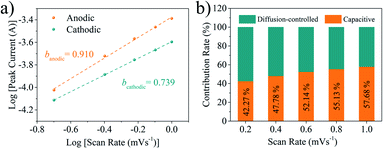 | ||
| Fig. 6 (a) Linear relationship between log(i) and log(ν) at different voltages. (b) The ratios of pseudocapacitive and diffusion controlled contributions of SPC-180 electrode at different scan rates. | ||
Conclusion
In summary, S-doped carbon materials were prepared by spray drying and subsequent carbonization using SBR as the carbon source. When it is used as anode in sodium-ion battery, the SPC-180 electrodes exhibit high capacity and stable cycling performance at high rates. The excellent electrochemical performance is beneficial to the excess reaction sites for sodium-ion storage provided by S-doping, and the short sodium-ion diffusion pathway of the porous structure. Furthermore, the pseudocapacitive behaviour is the main reason for its high rate performance. Overall, this work provides a low-cost way for large-scale preparation of high-performance carbon based anode materials for sodium ion batteries.Conflicts of interest
There are no conflicts to declare.Acknowledgements
This work was supported by The National Key Research and Development Plan of China (2016YFB0700302) and The International S&T Cooperation Program of China (2015DFR50580).Notes and references
- Z. Hong, Y. Zhen, Y. Ruan, M. Kang, K. Zhou, J. M. Zhang, Z. Huang and M. Wei, Adv. Mater., 2018, 30, 1802035 CrossRef PubMed; J. J. Kim, K. Yoon, I. Park and K. Kang, Small Methods, 2017, 1, 1700219 CrossRef; C. Yang, J. Xiong, X. Ou, C.-F. Wu, X. Xiong, J.-H. Wang, K. Huang and M. Liu, Mater. Today Energy, 2018, 8, 37 CrossRef.
- S. Wenzel, T. Hara, J. Janek and P. Adelhelm, Energy Environ. Sci., 2011, 4, 3342 RSC.
- Y. Liang, W. Lai, Z. Miao and S. L. Chou, Small, 2018, 14, 1702514 CrossRef PubMed.
- Y. Wang, S.-L. Chou, H. Liu and S.-X. Dou, Carbon, 2013, 57, 202 CrossRef CAS.
- H. Lu, L. Wu, L. Xiao, X. Ai, H. Yang and Y. Cao, Electrochim. Acta, 2016, 190, 402 CrossRef CAS; Y. Zhao and A. Manthiram, Chem. Mater., 2015, 27, 3096 CrossRef.
- Y. Wang, Y. Lim, M. Park, S.-L. Chou, J. Kim, H. Liu, S.-X. Dou and Y. Kim, J. Mater. Chem. A, 2014, 2, 529 RSC.
- L. Zhang, X. Liu, Y. Dou, B. Zhang, H. Yang, S. Dou, H. Liu, Y. Huang and X. Hu, Angew. Chem., Int. Ed., 2017, 56, 13790 CrossRef CAS PubMed.
- J. Li, L. Han, D. Zhang, J. Li, T. Lu, X. Wang and L. Pan, Inorg. Chem. Front., 2019, 6, 2104 RSC.
- Y. Fan, X. Meng, H. Li, S. Kuang, L. Zhang, Y. Wu, Z. Wang and G. Zhu, Adv. Mater., 2017, 29, 1603115 CrossRef CAS PubMed; D. Wang, F. Li, M. Liu, G. Lu and H. Cheng, Angew. Chem., Int. Ed., 2008, 47, 373 CrossRef PubMed; C. Liang, K. Hong, G. Guiochon, J. Mays and S. Dai, Angew. Chem., Int. Ed., 2004, 43, 5785 CrossRef PubMed; Y. Hu, P. Adelhelm, B. Smarsly, S. Hore, M. Antonietti and J. Maier, Adv. Funct. Mater., 2007, 17, 1873 CrossRef.
- W. Li, M. Zhou, H. Li, K. Wang, S. Cheng and K. Jiang, Energy Environ. Sci., 2015, 8, 2916 RSC.
- A. Ferrari and J. Robertson, Phys. Rev. B: Condens. Matter Mater. Phys., 2000, 61, 14095 CrossRef CAS.
- X. Zhang, G. Zhu, M. Wang, J. Li, T. Lu and L. Pan, Carbon, 2017, 116, 686 CrossRef CAS.
- J. Li, W. Qin, J. Xie, H. Lei, Y. Zhu, W. Huang, X. Xu, Z. Zhao and W. Mai, Nano Energy, 2018, 53, 415 CrossRef CAS.
- H. Yang, C. Zhang, Q. Meng, B. Cao and G. Tian, J. Power Sources, 2019, 431, 114 CrossRef CAS.
- D. W. Xu, S. Xin, Y. You, Y. Li, H. Cong and S. Yu, ChemNanoMat, 2016, 2, 712 CrossRef CAS.
- P. Bai, X. Han, Y. He, P. Xiong, Y. Zhao, J. Sun and Y. Xu, Energy Storage Mater., 2020, 25, 324 CrossRef CAS; W. Liu, M. Wei, L. Ji, Y. Zhang, Y. Song, J. Liao and L. Zhang, Chem. Phys. Lett., 2020, 741, 13706 CrossRef; J. Ou, L. Yang, Z. Zhang and X. Xi, Microporous Mesoporous Mater., 2017, 237, 23 CrossRef; Y. Sun, P. Lu, X. Liang, C. Chen and H. Xiang, J. Alloys Compd., 2019, 786, 468 CrossRef; Z. Yan, Y. Liang, J. Xiao, W. Lai, W. Wang, Q. Xia, Y. Wang, Q. Gu, H. Lu, S.-L. Chou, Y. Liu, H. Liu and S.-X. Dou, Adv. Mater., 2020, 32, 1906700 CrossRef PubMed.
- M. S. Balogun, Y. Luo, W. Qiu, P. Liu and Y. Tong, Carbon, 2016, 98, 162 CrossRef CAS.
- F. Xie, L. Zhang, D. Su, M. Jaroniec and S.-Z. Qiao, Adv. Mater., 2017, 29, 1700989 CrossRef PubMed.
- N. He, L. Zhong, M. Xiao, S. Wang, D. Han and Y. Meng, Sci. Rep., 2016, 6, 33871 CrossRef CAS PubMed.
- Y. Li, B. Ni, X. Li, X. Wang, D. Zhan, Q. Zhao, J. Li, T. Lu, W. Mai and L. Pan, Nano-Micro Lett., 2019, 11, 60 CrossRef.
- C. Chen, Y. Wen, X. Hu, X. Ji, M. Yan, L. Mai, P. Hu, B. Shan and Y. Huang, Nat. Commun., 2015, 6, 6929 CrossRef CAS PubMed.
- V. Augustyn, P. Simon and B. Dunn, Energy Environ. Sci., 2014, 7, 1597 RSC; C. Choi, D. S. Ashby, D. M. Butts, R. H. DeBlock, Q. Wei, J. Lau and B. Dunn, Nat. Rev. Mater., 2019, 5, 5 CrossRef CAS.
Footnote |
| † Electronic supplementary information (ESI) available. See DOI: 10.1039/d0ra02596h |
| This journal is © The Royal Society of Chemistry 2020 |

