 Open Access Article
A chemically bonded supercapacitor using a highly stretchable and adhesive gel polymer electrolyte based on an ionic liquid and epoxy-triblock diamine network†
You Kyung Han ab,
Jae Yeong Cheonb,
Taehoon Kimb,
Sang Bok Leeb,
Yang Do Kim*a and
Byung Mun Jung*b
aDepartment of Materials Science and Engineering, Pusan National University, Busan, 46241, Republic of Korea
bFunctional Composite Department, Korea Institute of Materials Science (KIMS), Changwon 51508, Korea
First published on 19th May 2020
Abstract
Despite significant advances in the development of flexible gel polymer electrolytes (GPEs), there are still problems to be addressed to apply them to flexible electric double layer capacitors (EDLCs), including interfacial interactions between the electrolyte and electrode under deformation. Previously reported EDLCs using GPEs have laminated structures with weak interfacial interactions between the electrode and electrolyte, leading to fragility upon elongation and low power density due to lower utilization of the surface area of the carbon material in the electrode. To overcome these problems, we present a new strategy for constructing an epoxy-based GPE that can provide strong adhesion between electrode and electrolyte. The GPE is synthesized by polymerization of epoxy and an ionic liquid. This GPE shows high flexibility up to 509% and excellent adhesive properties that enable strong chemical bonding between the electrode and electrolyte. Moreover, the GPE is stable at high voltage and high temperature with high ionic conductivity of ∼10−3 S cm−1. EDLCs based on the developed GPE exhibit good compatibility between the electrode and electrolyte and work properly when deformed. The EDLCs also show a high specific capacitance of 99 F g−1, energy density of 113 W h kg−1, and power density of 4.5 kW g−1. The excellent performance of the GPE gives it tremendous potential for use in next generation electronic devices such as wearable devices.
Introduction
Recent advances in mobile and miniaturized electronics1–4 have promoted the development of flexible and deformable power supplies that are both robust and sustainable. Among various energy storage devices, electric double-layer capacitors (EDLCs)6 have been considered as promising candidates because of their high power density and excellent reliability in a wide temperature range. When EDLCs are applied in a flexible device, the device has to work properly during deformation. However, typical liquid electrolyte-based EDLCs suffer from safety issues such as leakage and volatility of electrolyte when deformed. On the other hand, solid electrolytes offer a simple strategy to fabricate safe and inexpensive packing. Especially, gel polymer electrolyte (GPE) has been recognized as a compelling alternative, showing reasonable ionic conductivity despite great flexibility that can be seen in its stretchable, bendable, foldable and even twistable properties.GPE is composed of a polymer host such as poly(vinyl alcohol)(PVA),8,9 poly(methylmethacrylate) (PMMA),11,12 polyacrylic acid (PAA),13,14 poly(vinylidene fluoride) (PVDF)15,16 with salt, and a solvent such as an aqueous solvent,17,18 organic solvent19,20 or ionic liquid.21,22 These solvents are responsible for the ion conductivity and operating voltage window of the GPE. Among them, ionic liquids have a number of advantages including non-volatility, non-flammability, and wide electrochemical stability window.23 Combinations of ionic liquids and polymers have been proposed recently because of their high electrochemical stability over a wide voltage window. These characteristics lead to high energy density than the organic and aqueous solvent.24–26
Typically, used for flexible EDLC, GPEs in thin film shape are placed independently between two electrodes.27 The electrical energy of the EDLCs is stored through the separation of charged substances in an electrochemical double layer across the interface between the electrode and electrolyte. In order to obtain higher energy density of EDLC, especially for flexible electronics, one of the necessary requirements is an electrolyte that can make full use of the surface areas of carbon materials. EDLCs including typical GPEs cannot utilize all available carbon materials. This problem can be solved by using a liquid state GPE before polymerization. Liquid state GPEs can contact all of carbon materials, even inside the electrode; then, the GPE is polymerized between the two electrodes. However, there is another problem with this EDLC; its components such as electrolyte or electrode are prone to detachment when the cell is twisted or bent. As a result of deformation, the device does not work as ion path way is unavailable. Therefore, GPE for flexible EDLC is required to exhibit not only flexibility but also adhesion, so as to promote interaction between electrode and electrolyte. This is possible with the introduction of a polymer that exhibits adhesive properties such as an epoxy.
In this work, we demonstrate the synthesis of a stretchable and adhesive GPE for flexible EDLCs by introduction epoxy and an ionic liquid. Because of polymerization with the ionic liquid, the developed GPE has high ionic conductivity and electrochemical stability. The epoxy we used contains amine terminated poly ethylene oxide (PEO) copolymer; the long PEO chain imparts great flexibility and the resulting GPE becomes highly stretchable and flexible. In addition, the epoxy added to GPE yields an adhesive property that maintains contact between electrolyte and electrode under cell deformation. Finally, great electrochemical performance is demonstrated in cells assembled with the developed GPE under deformation.
Experimental
Materials
Diglycidyl ether of bisphenol A (DGEBA, Mw = 184 g mol−1, Kukdo chemical, Korea), O,O′-bis (2-aminopropyl) polypropylene glycol-block-polyethylene glycol-block-polypropylene glycol (Jeffamine ED-2003, Mw = 1900 g mol−1, Jeffamine ED-900 Mw = 900 g mol−1, Sigma-Aldrich, Korea), and triethylenetetramine (TETA, Mw = 146 g mol−1, Sigma-Aldrich, Korea) are used for the polymer matrix. 1-Ethyl-3-methylimidazoliumbis (trifluoromethylsulfonyl) imide (EMImTFSI, Mw = 391 g mol−1, Sigma-Aldrich, Korea) was prepared as both ion conductor and solvent. For the EDLCs, the active material of the electrode is a mixture of 80 wt% activated carbon (AC) powder with a surface area of 2000 m2 g−1 (MTI Korea, Korea), 15 wt% conductive carbon with a surface area of 62 m2 g−1 (MTI Korea, Korea) and 5% carboxymethyl cellulose (CMC, MTI Korea, Korea) powder.Preparation of epoxy
For the polymer matrix of GPE, epoxy solution was prepared as a mixture of DGEBA, Jeffamine, and TETA. Three types of GPE were fabricated and given denotation of GPE-1, GPE-2 and GPE-3. We mainly dealt with GPE-3; the others were fabricated for comparison of ionic conductivity and the mechanical property. The ratio of DGEBA, Jeffamine ED-900, Jeffamine ED-2003, and TETA for GPE-3 is 1![[thin space (1/6-em)]](https://www.rsc.org/images/entities/char_2009.gif) :
:![[thin space (1/6-em)]](https://www.rsc.org/images/entities/char_2009.gif) 1.5
1.5![[thin space (1/6-em)]](https://www.rsc.org/images/entities/char_2009.gif) :
:![[thin space (1/6-em)]](https://www.rsc.org/images/entities/char_2009.gif) X
X![[thin space (1/6-em)]](https://www.rsc.org/images/entities/char_2009.gif) :
:![[thin space (1/6-em)]](https://www.rsc.org/images/entities/char_2009.gif) 0.18. For analysis of the mechanical property according to the amount of Jeffamine ED-2003, X (the amount of Jeffamine ED-2003) had values of 1.5, 1.6, 1.7, and 1.8. Otherwise, X was fixed at 1.8. Since Jeffamine ED-2003 is in a solid state at room temperature, it was first added to DGEBA and stirred at 60 °C until solution became homogeneous. For this, Jeffamine ED-900 and TETA were dissolved and stirred for 2 h at RT and then vacuum filtered. The epoxy solution for GPE-1 is a mixture of DGEBA and Jeffamine ED-900 (1
0.18. For analysis of the mechanical property according to the amount of Jeffamine ED-2003, X (the amount of Jeffamine ED-2003) had values of 1.5, 1.6, 1.7, and 1.8. Otherwise, X was fixed at 1.8. Since Jeffamine ED-2003 is in a solid state at room temperature, it was first added to DGEBA and stirred at 60 °C until solution became homogeneous. For this, Jeffamine ED-900 and TETA were dissolved and stirred for 2 h at RT and then vacuum filtered. The epoxy solution for GPE-1 is a mixture of DGEBA and Jeffamine ED-900 (1![[thin space (1/6-em)]](https://www.rsc.org/images/entities/char_2009.gif) :
:![[thin space (1/6-em)]](https://www.rsc.org/images/entities/char_2009.gif) 2). The epoxy solution for GPE-2 is a mixture of DGEBA, Jeffamine ED2003 and TETA (1
2). The epoxy solution for GPE-2 is a mixture of DGEBA, Jeffamine ED2003 and TETA (1![[thin space (1/6-em)]](https://www.rsc.org/images/entities/char_2009.gif) :
:![[thin space (1/6-em)]](https://www.rsc.org/images/entities/char_2009.gif) 3
3![[thin space (1/6-em)]](https://www.rsc.org/images/entities/char_2009.gif) :
:![[thin space (1/6-em)]](https://www.rsc.org/images/entities/char_2009.gif) 0.18).
0.18).
Preparation of gel polymer electrolyte (GPE)
The ionic liquid EMImTFSI was added to the epoxy solution and mixture was stirred using a mechanical stirrer until it became a clear homogenous solution. To optimize the ratio between the epoxy and EMImTFSI, various weight percentages of EMImTFSI to total GPE solution were added. Then, these viscous solutions were poured into silicon dishes and cured at 130 °C for 4 h. Finally, the film shape of GPE was obtained.Preparation of electrode and fabrication of EDLC
The carbon slurry of electrode material for EDLC is a mixture of AC, CC, and binder CMC powder of which the weight ratio is 8![[thin space (1/6-em)]](https://www.rsc.org/images/entities/char_2009.gif) :
:![[thin space (1/6-em)]](https://www.rsc.org/images/entities/char_2009.gif) 1.5
1.5![[thin space (1/6-em)]](https://www.rsc.org/images/entities/char_2009.gif) :
:![[thin space (1/6-em)]](https://www.rsc.org/images/entities/char_2009.gif) 0.5; this material is dissolved in water and constantly mixed until becoming a homogeneous slurry. Subsequently, using doctor blade, the slurry was cast on an aluminum foil current collector. The obtained electrode was dried under vacuum at 80 °C overnight to eliminate moisture effects. To fabricate the EDLCs, a GPE-3 solution before curing and nonwoven glass fiber (separator) was sandwiched between two electrodes and device layer were pressed together. Then, chemically bonded EDLC was fabricated by curing of GPE between two electrodes at 130 °C for 4 h.
0.5; this material is dissolved in water and constantly mixed until becoming a homogeneous slurry. Subsequently, using doctor blade, the slurry was cast on an aluminum foil current collector. The obtained electrode was dried under vacuum at 80 °C overnight to eliminate moisture effects. To fabricate the EDLCs, a GPE-3 solution before curing and nonwoven glass fiber (separator) was sandwiched between two electrodes and device layer were pressed together. Then, chemically bonded EDLC was fabricated by curing of GPE between two electrodes at 130 °C for 4 h.
Measurement
For analysis of chemical structure, Fourier transformation infra-red (FTIR) spectra were obtained using a Nicolet iS10 FTIR spectrometer (Thermo Scientific) with diamond attenuated total reflectance (ATR). The crystalline phases were analyzed using an X-ray diffractometer (XRD, Rigaku D/MAX 2500VL) in 10–40° angle range with Cu Kα radiation. Using broadband dielectric relaxation spectroscopy (DRS, Novocontrol GmbH concept 40), the ionic conductivity of the electrolytes was measured in a temperature range of −50 °C to 120 °C in a frequency range of 1 Hz to 100 Hz under nitrogen atmosphere. For this measurement, a thin film shaped sample was sandwiched between top brass electrode (10 mm diameter) and bottom brass electrode (30 mm diameter). The mechanical test was carried out on a universal testing machine (UTM, Instron 3344) with 5 N load cell at a stretching speed of 100% min−1. Adhesion test was performed with an ASTM D3359. Cyclic voltammetry (CV) and galvanostatic charge discharge (GCD) were performed using a VSP300 of Bio-Logic Science Instruments in two-electrode configuration. CV curves of the EDLCs were draw at a scan rate of 20 to 100 mV s−1 in a potential window from 0 to 3 V. The GCD test was conducted at constant current densities of 0.2 A g−1 to 2 A g−1.Results and discussion
Physicochemical characterization of the gel polymer electrolyte
Epoxy as a polymer matrix of GPE is formed by a simple crosslinking reaction of the epoxide ring and amine group called curing as illustrated in Fig. 1. One of the common epoxy resins, DGEBA, has various properties such as high toughness, high temperature stability, chemical resistance, and adhesion. These properties make the electrolyte work properly under difficult conditions.28 Amines are known as the most common curing agent; the epoxy-amine network can control the crosslinking density or the chemical structure by tuning the network architecture.29–31 Steric restrictions at crosslinking points affect the packing of chains and increase the free volume characteristics of the epoxy-amine networks.32,33 Therefore, the flexible gel structure of GPE can be formed by introduction of a high molecular amine with long polymer chains.34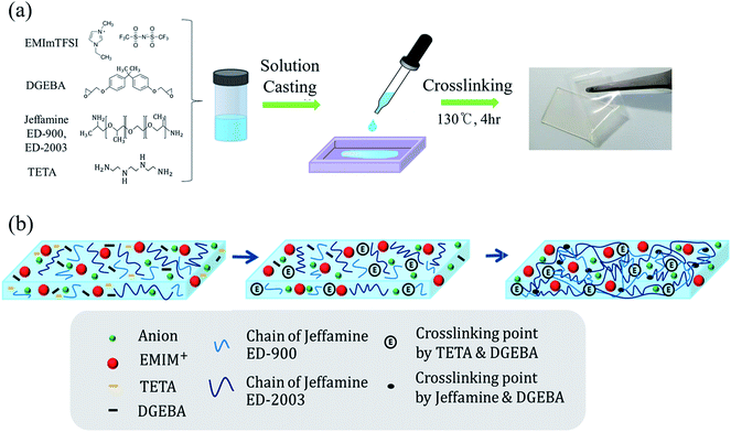 | ||
| Fig. 1 Illustration of (a) synthetic procedure for preparation of GPE-3 through solution casting; (b) polymerization procedure of GPE-3 from reaction between DEGBA and Jeffamine. | ||
By adding the amine-terminated polyethylene oxide (PEO) copolymer called Jeffamine, we designed a flexible GPE. Because various types of Jeffamine exist according to the molecular weight of PEO, we introduced a double network using two different types of Jeffamine to synthesize a stretchable GPE for flexible EDLCs. Polymer networks with relatively short and long polymer chains controlled mechanical properties of GPE. Jeffamine ED-2003 containing long PEO chain contribute to flexibility of GPE. Jeffamine ED-900 with short PEO chain enhance the fracture energy by dissipating mechanical energy. The first reaction of the curing step occurred between DGEBA and TETA due to their low reaction temperature, as shown in Fig. 1. Adding TETA can lead to high crosslinking density leading to high strength.35 However, most of the DGEBA reacted with Jeffamine because of its large quantity as a curing agent. Therefore, Jeffamine is responsible for the vast majority of the physicochemical properties of GPE. Jeffamine is an amine-terminated PEO copolymer. Amines that terminated in Jeffamine react with DEGBA to produce crosslinking points and long PEO chains of synthesized electrolytes, to which Jeffamine contributes flexibility. Also, because ionic liquids have good compatibility with Jeffamine, ionic liquid exist homogeneously in the polymer matrix. The resulting GPE, based on ionic liquid and epoxy derived from Jeffamine, make it possible to take advantage of the properties of the both materials.36 The GPE-3 film formed by the solution casting method was flexible and transparent, as shown in Fig. 1(a).
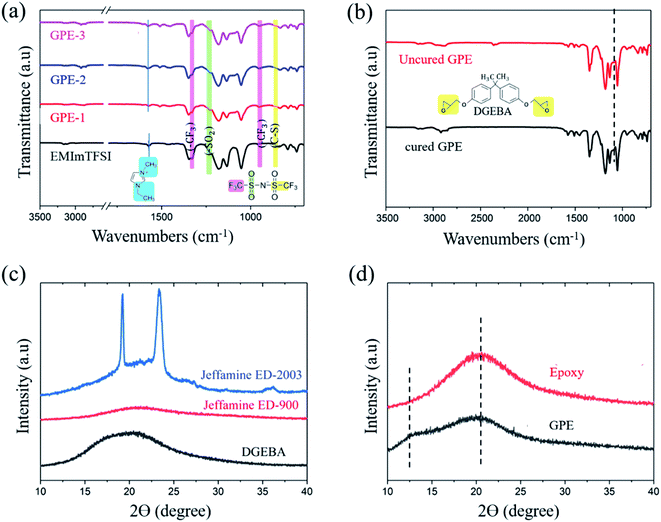
Fig. 2 shows the ATR-FTIR characteristic peak of monomers and crosslinked GPE. CH2(N)/CH3(N) symmetric and asymmetric stretching in EMImTFSI corresponded to the peak at 1570 cm−1, which was shifted to 1578 cm−1 for GPE-1, GPE-2, and GPE-3; the vibration of the [EMIm]+ cation peak was indicative of the high degree of freedom of the ions of the GPEs.37 The formation of a crosslinked structure can be confirmed in Fig. 2(b). The peak at 913 cm−1 corresponded to the epoxide group, but disappeared after the reaction of DGEBA and Jeffamine.38 Thus, it can be concluded that epoxide groups reacted with amines through the ring opening reaction, indicating the successful completion of the crosslinking reaction. To investigate structural changes when EMImTFSI was added to the GPE, X-ray diffraction (XRD) characterization was performed with results shown in Fig. 2(d). The semi-crystallinity of PEO, which was the result of the addition of Jeffamine ED-2003, corresponded to the peaks at 2θ = 19.5° and 23.75° as shown in Fig. 2(c). The epoxy (GPE without EMImTFSI) shows a broadened band because of its low crystallinity. When EMImTFSI was added to the epoxy solution, the peak at 2θ = 13° appeared due to movement of the polymer chains. EMImTFSI is placed between polymer chains, causing movement of the PEO chains and modification of the structure of the epoxy to GPE-3. These results confirm that the added EMImTFSI is homogeneously distributed in the polymer host.
Ionic conductivity of GPE
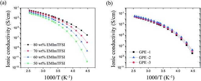
The high ionic conductivity of the GPE originates from EMImTFSI trapped in the polymer matrix. Therefore, in order to determine the optimum contents of EMImTFSI in GPE-3, we investigated the ionic conductivity of GPE films with various contents of EMImTFSI. Fig. 3(a) shows the temperature dependence of the ionic conductivity of the GPEs from −50 °C to 120 °C. The ionic conductivity increased with increasing EMImTFSI loading from 50 to 80 wt%, following the Arrhenius equation (i.e., a linear relationship between log (σ) and 1/T), eqn (1):
 | (1) |
All results for ionic conductivity of GPE show similar tendencies with increasing temperature, as shown in Fig. 3(a). This means that phase transition and decomposition did not take place within this temperature range.39 Thermal stability of GPE is also indicated by its decomposition temperature of 265 °C, determined by TGA and shown in Fig. S1.† This excellent thermal stability is a key factor in the safety of EDLCs. At 25 °C, the measured ion conductivity of GPE-3 containing 70 wt% EMImTFSI was approximately 1.2 × 10⁻³ S cm−1. This value is comparable to that of neat EMImTFSI (3.4 × 10⁻³ S cm−1). Ionic conductivity values of GPE-1, GPE-2 and GPE-3 showed very little difference, as can be seen in Fig. 3(b). In the case of GPE-2, each crosslinking points are spaced out by long PEO chain of Jeffamine ED-2003. As a result, there is less obstruction than in the others and this leads to high ionic conductivity. Therefore, the ionic conductivity value of GPE-2 is slightly higher than that of GPE-3. However, the difference in value of GPEs using Jeffamine ED-2003 is negligible as the ionic conductivities of GPE-3 and GPE-2 are 1.2 × 10⁻³ s cm−1 and 1.8 × 10⁻³ s cm−1, both of which make these materials suitable for use as electrolytes. However, the studies of the mechanical property of GPE-1, GPE-2, and GPE-3 offered conflicting results.
Mechanical property of GPE
The mechanical property of the prepared GPE was characterized as shown in Fig. 4. One-pot synthesis of GPE with Jeffamine ED-2003 and ED-900 improved the mechanical property by introducing a flexible segment into the hard segment. GPE-3 has a better maximum strain than GPE-1 and a better tensile strength than GPE-2. As can be seen in Fig. 4(b), Jeffamine ED-2003, because of its long PEO chains, makes a flexible segment with DGEBA and induce flexibility in GPE-3. On the other hand, a hard segment crosslinked with Jeffamine ED-900 and DGEBA can be fractured, dissipating the mechanical energy in GPE-3. According to the mechanical deformation, the hard segment can break first to dissipate the strain energy; the fracture energy of GPE-3 is thereby enhanced (Fig. 4(a) and (b)). Results for flexibility according to added Jeffamine ED-2003 are shown in Fig. 4(c). Breaking strength showed similar values because all of the GPEs shown in Fig. 4(c) contain the same amount of TETA, which is responsible for mechanical strength. On the other hand, strain increased with added Jeffamine ED-2003, which is responsible for flexibility, and the maximum strain of GPE-3 was approximately 509%. Compared with the other ionic liquid based GPE, without salt, GPE-3 achieves good compatibility between high ionic conductivity and flexibility, as indicated in Fig. 4(d).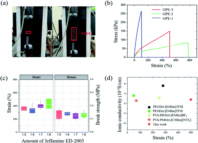 | ||
| Fig. 4 (a) Strain of GPE-3; (b) strain–stress curves of GPE-1, GPE-2 and GPE-3; (c) strain and stress of GPE-3 according to amount of Jeffamine ED-2003 added; (d) strain according to ionic conductivity of GPE-3, PEGDA/[EMIm]TFSI,1 PEGDA/[EMIm]TFSI,5 PVA/HEMA/[EMIm]BF4,7 and PVA/PMMA/[CMIm][NTf2].10 | ||
Adhesive property of GPE
The adhesive property of the GPE is another important requirement because adhesion maintains the interface between electrode and electrolyte when the cell is stretched, rolled or bent. In short, the adhesive property of GPE helps the electrolyte maintain contact with the electrode. Unless this connection appears, GPE might have excellent flexibility, but the cell will not work when deformed. This adhesive property of GPE is investigated according to ASTM D3359 B. Test specimens were glass and aluminum plates; these two substrates are used as a glass fiber nonwoven separator and the aluminum foil current collector. The test results are shown in Fig. 5, indicating, because none of the squares of the lattice is detached, that the adhesion of GPE-3 to glass and aluminum is strong.40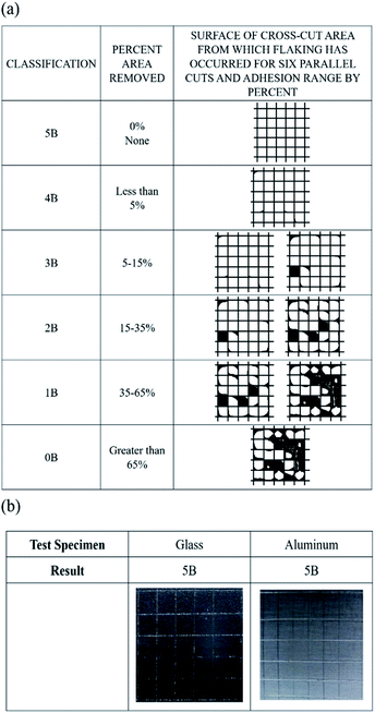 | ||
| Fig. 5 (a) Classification of adhesion test results according to ASTM D3359 (b) photographs of adhesion test results of GPE-3 with glass and aluminum. | ||
Fabrication and performance characteristics of EDLCs based on GPE-3
A flexible EDLC cell was fabricated using AC as active material, Al foil as current collector, and GPE-3 as electrolyte, as illustrated in Fig. 6(a). The appropriate amount of gel solution was placed between two electrodes facing each other and cell was polymerized. Since GPE-3 has an adhesive property, it holds the two electrodes together, and the cell does not come apart even under twisting as shown in Fig. 6(a). Gel solution is impregnated into the electrode layer; thus, the carbon surface in the electrode can be fully utilized for interfacial contact. Fig. 6(b) provides a cross-sectional SEM image of the interface between the electrode and GPE in the prepared flexible EDLCs. The electrode layer and GPE-3 had good contact and formed capacitive interfaces.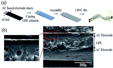 | ||
| Fig. 6 (a) Illustration of polymerization procedure of GPE (ED2003/ED900); (b) SEM image of cross section of EDLC and interface of GPE (ED2003/ED900) and AC based electrode. | ||
Electrochemical performance of EDLCs based on GPE-3
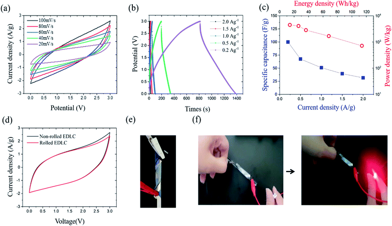
The electrochemical performance of the EDLC cell was characterized by cyclic voltammetry (CV) and galvanostatic charge–discharge (GCD) test at room temperature. The operating potential window (OPW) was first studied using linear sweep voltammetry (LSV) at a scan rate of 1 mV s−1 (Fig. S2†). The GPE-3 exhibits a OPW of 3.3 V, which is close to that of neat EMImTFSI.37 Therefore, voltage window of 3 V was utilized in electrochemical tests of EDLC. Fig. 7(a) shows CV profiles at different scan rates from 20 mV s−1 to 100 mV s−1, indicating capacitive behavior of the prepared cell. Fig. 7(b) shows GCD profiles of the EDLCs at different current density ranging from 2.0 A g−1 to 0.2 A g−1. The triangular shape of the charge and discharge curves indicate the electric double layer capacitive behaviour; the specific capacitance (CGCDs) is calculated using the following equation, eqn (2):
 | (2) |
| Electrolytea | Specific capacitance (F g−1) | Ref. |
|---|---|---|
| a [PMpyr][NTf2] represents 1-methyl-1-propylpyrrolidinium bis(trifluoromethyl sulfonyl) imide, BMIM BF4 represents 1-butyl-3-methylimidazolium tetrafluoroborate, CH3COONH4 represents ammonium acetate, BMIMPF6 represents 1-butyl-3-methylimidazolium hexafluorophosphate, poly(VPIFSI) represents poly(1-vinyl-3-propylimidazoliumbis(fluorosulfonyl)imide), EMIFSI represent 1-ethyl-3-methyl imidazolium bis(fluorosulfonyl)imide (EMIFSI), EMIMBF4 represents 1-ethyl-3-methylimidazolium iodide, Bp represents benzophenone, hBN represents hexagonal boron nitride, and PSU represents polysulfone. | ||
| GPE-3 | 99 | This work |
| PVdF/PVAc/BMIMBF4 | 93.3 | 41 |
| PVA/A–CH3COONH4/BMIMPF6 | 72.58 | 42 |
| poly(VPIFSI)/EMIFSI | 52.7 | 43 |
| PEO/PEGMA/EMIMBF4 | 74 | 44 |
| PEO/Bp/EMImTFSI | 70.84 | 45 |
| PSU/hBN/EMImTFSI | 90.4 | 46 |
| PVdF-HFP/[PMpyr][NTf2] | 93.72 | 47 |
To verify the flexibility of the prepared EDLC, we performed electrochemical characterization under deformable condition, with result shown in Fig. 7(e). The CV and GCD profiles were nearly identical regardless of the bending conditions (Fig. 7(d)). Fig. 7(f) shows that, in charge–discharge process, the device worked well in powering an LED. Cyclic test was also conducted on EDLC and EDLC under the bending condition at current density of 2 A g−1. Both EDLC exhibited a capacitance retention of more than 85% of its initial capacitance after 100 cycles and a coulombic efficiency of 100% during the cycle (Fig. S3†). Nyquist impedance plots of the EDLC before and after cyclic test from 1 MHz to 10 MHz frequency range at small ac voltage 5 mV is shown in Fig. S4.† In lower frequency region, impedance curve show a nearly vertical line, which confirms the capacitive behaviour, and the shape of the line is maintained after cyclic test. The intercept at high frequency region shows bulk solution resistance. Before cyclic test, the bulk solution resistance is 6.7 Ω and the resistance slightly increased to 7.3 Ω after test.
Conclusions
In conclusion, by introduction epoxy and ionic liquid, we fabricated a stretchable and adhesive GPE for flexible EDLC. This GPE had not only high ionic conductivity (1.8 × 10⁻³ S cm−1) but also good electrochemical stability because of the polymerization with the ionic liquid. Moreover, the introduction of the epoxy led to strong adhesive property and flexibility of up to 509% of GPE. Based on this GPE, flexible EDLC that can work under deformable conditions are fabricated showing improved interfacial interaction between electrolyte and electrode. Additionally, this EDLC delivered a maximum energy density of 113 W h kg−1 and a maximum power density of 4.48 kW kg−1 for operation within a 3 V window. In short, our work has tremendous potential for use in next generation electronic devices such as wearable devices.Conflicts of interest
The authors declare that they have no conflict of interest.Acknowledgements
This research was supported by the Fundamental Research Program (PNK6660) of the Korea Institute of Materials Science (KIMS).References
- X. Cai, B. Cui, B. Ye, W. Wang, J. Ding and G. Wang, ACS Appl. Mater. Interfaces, 2019, 11, 38136–38146 CrossRef CAS PubMed.
- V. L. Pushparaj, M. M. Shaijumon, A. Kumar, S. Murugesan, L. Ci, R. Vajtai, R. J. Linhardt, O. Nalamasu and P. M. Ajayan, Proc. Natl. Acad. Sci. U. S. A., 2007, 104, 13574–13577 CrossRef CAS.
- X. Wang, X. Lu, B. Liu, D. Chen, Y. Tong and G. Shen, Adv. Mater., 2014, 26, 4763–4782 CrossRef CAS PubMed.
- L. Li, Z. Wu, S. Yuan, X.-B. J. E. Zhang and E. Science, Energy Environ. Sci., 2014, 7, 2101–2122 RSC.
- Y. Zhong, G. T. Nguyen, C. d. Plesse, F. d. r. Vidal and E. W. Jager, ACS Appl. Mater. Interfaces, 2018, 10, 21601–21611 CrossRef CAS PubMed.
- P. Sharma and T. Bhatti, Energy Convers. Manage., 2010, 51, 2901–2912 CrossRef CAS.
- H. H. Rana, J. H. Park, E. Ducrot, H. Park, M. Kota, T. H. Han, J. Y. Lee, J. Kim, J.-H. Kim and P. Howlett, Energy Storage Mater., 2019, 19, 197–205 CrossRef.
- G. Wang, X. Lu, Y. Ling, T. Zhai, H. Wang, Y. Tong and Y. Li, ACS Nano, 2012, 6, 10296–10302 CrossRef CAS PubMed.
- A. Awadhia, S. Patel and S. Agrawal, Prog. Cryst. Growth Charact. Mater., 2006, 52, 61–68 CrossRef CAS.
- T. Kawazoe, K. Hashimoto, Y. Kitazawa, H. Kokubo and M. Watanabe, Electrochim. Acta, 2017, 235, 287–294 CrossRef CAS.
- J. Vondrák, J. Reiter, J. Velická and M. Sedlařıková, Solid State Ionics, 2004, 170, 79–82 CrossRef.
- P. Meneghetti, S. Qutubuddin and A. Webber, Electrochim. Acta, 2004, 49, 4923–4931 CrossRef CAS.
- Z. Tang, Q. Liu, Q. Tang, J. Wu, J. Wang, S. Chen, C. Cheng, H. Yu, Z. Lan and J. Lin, Electrochim. Acta, 2011, 58, 52–57 CrossRef CAS.
- Z. Tang, J. Wu, Q. Liu, M. Zheng, Q. Tang, Z. Lan and J. Lin, J. Power Sources, 2012, 203, 282–287 CrossRef CAS.
- S. Senthilkumar, R. K. Selvan, J. Melo and C. Sanjeeviraja, ACS Appl. Mater. Interfaces, 2013, 5, 10541–10550 CrossRef CAS PubMed.
- P. Periasamy, K. Tatsumi, M. Shikano, T. Fujieda, Y. Saito, T. Sakai, M. Mizuhata, A. Kajinami and S. Deki, J. Power Sources, 2000, 88, 269–273 CrossRef CAS.
- L.-Q. Fan, J. Zhong, J.-H. Wu, J.-M. Lin and Y.-F. Huang, J. Mater. Chem. A, 2014, 2, 9011–9014 RSC.
- N. R. Chodankar, D. P. Dubal, G. S. Gund and C. Lokhande, J. Energy Chem., 2016, 25, 463–471 CrossRef.
- D. Saikia and A. Kumar, Electrochim. Acta, 2004, 49, 2581–2589 CrossRef CAS.
- M. Kufian, M. Aziz, M. Shukur, A. Rahim, N. Ariffin, N. Shuhaimi, S. Majid, R. Yahya and A. K. Arof, Solid State Ionics, 2012, 208, 36–42 CrossRef CAS.
- P. Wang, S. M. Zakeeruddin, I. Exnar and M. Grätzel, Chem. Commun., 2002, 2972–2973 RSC.
- Y. J. Kang, H. Chung, C.-H. Han and W. Kim, Nanotechnology, 2012, 23, 065401 CrossRef PubMed.
- M. Armand, F. Endres, D. R. MacFarlane, H. Ohno and B. Scrosati, Nat. Mater., 2009, 8, 621–629 CrossRef CAS PubMed.
- G. Pandey and S. Hashmi, Electrochim. Acta, 2013, 105, 333–341 CrossRef CAS.
- X. Zhang, L. Wang, J. Peng, P. Cao, X. Cai, J. Li and M. Zhai, Adv. Mater. Interfaces, 2015, 2, 1500267 CrossRef.
- R. Zhang, Y. Chen and R. Montazami, Materials, 2015, 8, 2735–2748 CrossRef CAS.
- Y.-F. Huang, P.-F. Wu, M.-Q. Zhang, W.-H. Ruan and E. P. Giannelis, Electrochim. Acta, 2014, 132, 103–111 CrossRef CAS.
- B. Qi, Q. Zhang, M. Bannister and Y.-W. Mai, Compos. Struct., 2006, 75, 514–519 CrossRef.
- O. Sindt, J. Perez and J. Gerard, Polymer, 1996, 37, 2989–2997 CrossRef CAS.
- N. Amdouni, H. Sautereau, J.-F. Gerard and J.-P. Pascault, Polymer, 1990, 31, 1245–1253 CrossRef CAS.
- C. Jordan, J. Galy and J. P. Pascault, J. Appl. Polym. Sci., 1992, 46, 859–871 CrossRef CAS.
- S. Goyanes, W. Salgueiro, A. Somoza, J. Ramos and I. Mondragon, Polymer, 2004, 45, 6691–6697 CrossRef CAS.
- K. Jeffrey and R. A. Pethrick, Eur. Polym. J., 1994, 30, 153–158 CrossRef CAS.
- P. N. Patil, S. K. Rath, S. K. Sharma, K. Sudarshan, P. Maheshwari, M. Patri, S. Praveen, P. Khandelwal and P. K. Pujari, Soft Matter, 2013, 9, 3589–3599 RSC.
- S. J. Kwon, T. Kim, B. M. Jung, S. B. Lee and U. H. Choi, ACS Appl. Mater. Interfaces, 2018, 10, 35108–35117 CrossRef CAS PubMed.
- J. P. Gong, Y. Katsuyama, T. Kurokawa and Y. Osada, Adv. Mater., 2003, 15, 1155–1158 CrossRef CAS.
- R. Na, C.-W. Su, Y.-H. Su, Y.-C. Chen, Y.-M. Chen, G. Wang and H. Teng, J. Mater. Chem. A, 2017, 5, 19703–19713 RSC.
- M. G. González, J. C. Cabanelas and J. Baselga, Applications of FTIR on epoxy resins-identification, monitoring the curing process, phase separation and water uptake, IntechOpen, Spain, 2012 Search PubMed.
- Y. Li, K. W. Wong, Q. Dou, W. Zhang, L. Wang and K. M. Ng, New J. Chem., 2017, 41, 13096–13103 RSC.
- Standard Test Methods for Rating Adhesion by Tape Test, https://www.astm.org/Standards/D3359.htm.
- L. Yang, J. Hu, G. Lei and H. J. Liu, Chem. Eng. J., 2014, 258, 320–326 CrossRef CAS.
- C.-W. Liew, S. Ramesh and A. J. Arof, Energy, 2016, 109, 546–556 CrossRef CAS.
- S. A. Alexandre, G. G. Silva, R. Santamaría, J. P. C. Trigueiro and R. L. J. Lavall, Electrochim. Acta, 2019, 299, 789–799 CrossRef CAS.
- M. Jin, Y. Zhang, C. Yan, Y. Fu, Y. Guo and X. Ma, ACS Appl. Mater. Interfaces, 2018, 10, 39570–39580 CrossRef CAS PubMed.
- X. Zhong, J. Tang, L. Cao, W. Kong, Z. Sun, H. Cheng, Z. Lu, H. Pan and B. J. Xu, Electrochim. Acta, 2017, 244, 112–118 CrossRef CAS.
- S. T. Gunday, E. Cevik, A. Yusuf and A. J. Bozkurt, J. Energy Storage, 2019, 21, 672–679 CrossRef.
- R. Muchakayala, S. Song, J. Wang, Y. Fan, M. Bengeppagari, J. Chen and M. J. Tan, J. Ind. Eng. Chem., 2018, 59, 79–89 CrossRef CAS.
Footnote |
| † Electronic supplementary information (ESI) available. See DOI: 10.1039/d0ra02327b |
| This journal is © The Royal Society of Chemistry 2020 |

