DOI:
10.1039/D0RA02263B
(Paper)
RSC Adv., 2020,
10, 20588-20594
The preparation and characterization of a carbon fiber-reinforced epoxy resin and EPDM composite using the co-curing method
Received
11th March 2020
, Accepted 9th May 2020
First published on 29th May 2020
Abstract
Due to the development of the aerospace technology, the requirements for composite materials have become stricter. Thus, in this work, a completely novel technology, which has not been reported elsewhere, was used to prepare a composite of a carbon fiber-reinforced epoxy resin (CFRP) and ethylene-propylene-diene rubber (EPDM), which was denoted as CFRP/EPDM; CFRP and EPDM are commonly used as a shell and heat insulation layer, respectively, in the solid rocket industry. The composite system had good adhesive ability, as confirmed by the 90° peel strength test, even though the EPDM rubber is non-polar in nature. Additionally, the adhesive mechanism between CFRP and EPDM was determined using scanning electron microscopy (SEM). Thermogravimetric analysis (TGA) indicated that the Td10% value of the CFRP/EDPM composite was slightly higher than that of CFRP. According to the nuclear magnetic resonance (NMR) spectroscopy results of the EPDM rubber and the interlaminar shear strength (ILSS) of CFRP, we can conclude that the co-curing method will not damage the properties of CFRP and EPDM.
Introduction
Because of their extraordinary strength-to-weight ratios and mechanical properties, carbon fiber (CF)-reinforced high-performance composites have made a huge impact on many structural applications, such as the aerospace and automotive industries.1–5 Generally speaking, the mechanical properties of carbon fiber-reinforced composites are dependent on the performance of the interface6 and to some extent, the heat resistance properties of a thermosetting resin are dependent on the curing agent. As we all know, epoxy resins (containing at least one epoxide or oxirane functional group) have a broad range of applications due to their wide-ranging dimensional, thermal, and environmental stabilities as well as their ease of processability.7 However, in order to obtain all of these remarkable properties, curing agents must be added into the curing system and the epoxy resin curing reaction is promoted or controlled by the curing agents.8 The curing agents of epoxy resins can be divided into different types and normally contain polyamines, acid anhydrides, or Lewis acids or bases.9 However, the epoxy resins cured by aromatic amines generally display better heat resistance and mechanical properties due to the existence of benzene rings.10
Because the ethylene-propylene-diene (EPDM) rubber consists of a saturated polymer backbone and an unsaturated double bond in the side group,11,12 it has excellent properties, such as superior heat, ozone, and irradiation resistance,13 low density, permanent deformation, and processability.14,15 However, there are also some disadvantages. Due to its non-polar nature because of its structure, its adhesive ability to other materials is very poor,16 and the polarity of the EPDM rubber will decrease further after the crosslinking process. Thus, when preparing composites that include EPDM rubber layers, we always have trouble obtaining perfect samples. In addition, in order to obtain the integrated crosslinked structures of the EPDM rubber, some suitable vulcanizing agents need to be added. The most widely used curing agents are sulfur and peroxides.17 However, the EPDM rubber is a saturated rubber and its unsaturated coefficient is relatively lower than that of other rubbers. Currently, choosing peroxide as a curing agent to vulcanize EPDM is very common. Several peroxides are used to vulcanize rubber in industries, and these include dibenzoyl peroxide (BPO), dicumyl peroxide (DCP), and tert-butyl cumyl peroxide (TBCP).18 As is well known, different crosslinked structures of rubber will be formed in the process of vulcanization and they have a strong influence on the properties of the rubber.19 Compared with sulfur curing, peroxide vulcanization has numerous advantages. The EPDM rubber vulcanized by peroxide mainly consists of C–C (352 kJ mol−1) bonds that have higher bond energy and better heat resistance.18 At the same time, the curing time and temperature of epoxy resins are much higher than those of EPDM rubbers (normally 30 min at 160 °C (ref. 12)). Thus, we chose peroxides as curing agents, which have better heat resistance and no obvious phenomenon of reversion, to prepare the CFRP/EPDM composite.
The preparation process of solid rocket motors (SRMs) including the propellent, heat insulation layer (EPDM, etc.), and shell (CFRP, etc.) can be generally classified into two main groups: cartridge-loaded and case-bonded.20 In the cartridge-loaded process, all the materials are cast and loaded into the motor, which is very complex and manual. The essence of the case-bonded process is adhesive. Some adhesive agents are applied on EPDM first until the adhesives are semi-cured to bond with each other;21 however, a lower adhesive strength is achieved because of the low polarity of the heat insulation layer normally used. In contrast, preparing thermoplastics and thermosetting material-based composites using the co-curing method is much more popular due to its cost-effectiveness, easy operation, and less drawbacks.22–24 For instance, the PEEK/CFRP composites were successfully fabricated using the co-curing method and strong adhesive strength was achieved.25 For natural or synthetic rubbers, co-curing adhesion with the metal parts is already widely used by adjusting the formula of the rubber,26,27 which may make many unexpected properties possible. However, there are no reports about the preparation of a thermosetting resin and rubber composite through this wonderful co-curing method, which may improve the properties of the materials and simplify the fabrication process compared to conventional approaches. In this work, a CFRP/EPDM composite was prepared via a one-step co-curing method and characterized using the 90° peel strength test, scanning electron microscopy (SEM), thermogravimetric analysis (TGA), nuclear magnetic resonance (NMR) spectroscopy, and interlaminar shear strength (ILSS) tests to determine its properties.
Experimental
Materials
CFs were obtained from Shanghai XiaoXi High-technology Material Co, China (6k, diameter: 7 μm). The E-51 epoxy resin (epoxy value = 0.51, volume shrinkage: 2.5%) was bought from Shandong Usolf Chemical Technology Co, Ltd. The EPDM rubber (ethylene content, 49–55 wt%; 5-ethylidene-2-norbornene content, 6.7–8.7 wt%) was purchased from Jilin Chemical Company, China. DCP (99%) was purchased from Guangzhou Huanzong Chemistry, China. Sulfur (S, 99%), m-phenylenediamine (MPD, 99%), and triallyl-isocyanurate (TAIC, 98%) were provided by Aladdin International Reagent Co, Ltd.
Preparation of EPDM rubber containing different additives
All the ingredients were weighed according to the formula in Table 1 and mixed with a two-roll mill at a whirling velocity of 1![[thin space (1/6-em)]](https://www.rsc.org/images/entities/char_2009.gif) :1 between the drive roll and driven roll. First, the EPDM rubber was put into the two-roll mill to crush it into a uniform thin layer. This was followed by the slow addition of the rest of the additives to this system. Then, this EPDM blend was extruded nine times to ensure better dispersion and the gap distance of the roll was set to less than 1 mm. Finally, the mixed materials were stripped off the roll and stored for 24 h for further experiments.
:1 between the drive roll and driven roll. First, the EPDM rubber was put into the two-roll mill to crush it into a uniform thin layer. This was followed by the slow addition of the rest of the additives to this system. Then, this EPDM blend was extruded nine times to ensure better dispersion and the gap distance of the roll was set to less than 1 mm. Finally, the mixed materials were stripped off the roll and stored for 24 h for further experiments.
Table 1 Compositions of the different formulations
| Sample name |
EPDM (g) |
DCP (g) |
S (g) |
TAIC (g) |
| EPDM-DCP |
100 |
3.5 |
0 |
0 |
| EPDM-DCP-S |
100 |
3.5 |
0.5 |
0 |
| EPDM-DCP-TAIC |
100 |
3.5 |
0 |
5.8 |
Preparation of epoxy prepreg
MPD was weighed and put into the oven at 115 °C for 20 min to obtain liquid MPD, which was used in the following steps of the experiment. Next, some epoxy resins were weighed and added to the liquid MPD system. At the same time, we should ensure that the mass ratio between the epoxy resin and MPD is 100:15. The epoxy/MPD blend, which was also used as the adhesive in this experiment, was stirred for 30 min by a high shear to obtain good homogeneity and then degassed in a vacuum oven at 50 °C in order to decrease the drawbacks of this system.28 Finally, the CFs were coated with the epoxy/MPD blend in an oven at 50 °C for 30 min to ensure better wettability and we obtained the epoxy prepreg.
Preparation of the CFRP and EPDM composite (CFRP/EPDM) by two methods
The epoxy prepreg was placed in a mold and then kept at 80 °C for 2 h without pressure, 120 °C for 2 h, 150 °C for 1 h under a pressure of 3 MPa, and 170 °C for 1 h to obtain CFRP. The EPDM rubber was obtained by maintaining the sample at 170 °C for 20 min. Then, the self-made adhesive mentioned before was painted onto the CFRP to bond with the EPDM rubber, all of which were maintained at 80 °C for 2 h and 140 °C for 2 h to obtain the CFRP/EPDM composite using the independent cured method.
The epoxy prepreg was transferred into a mold first, followed by placing a piece of separate paper, which is an indispensable item to ensure the possibility of 90° peel strength tests. Then, 3.5 g EPDM rubbers containing different additives were weighed and put into other molds for 30 min at a pressure of 3 MPa to obtain EPDM rubber strips. The strips helped remove the air in the EPDM rubber. The EPDM rubber strip was taken out from the mold and placed on the epoxy prepreg. Finally, this hybrid system was maintained at 80 °C for 2 h without pressure, 120 °C for 2 h, 150 °C for 1 h under a pressure of 3 MPa, and 170 °C for 1 h to obtain the final product.29 At the same time, the volume ratio between CFRP and EPDM was 1:1 and the fiber content was 65% in the CFRP system. The thickness of the sample was 5 mm.
Characterizations
The 90° peel strength test, as shown in Scheme 1, was carried out on a universal testing machine (5500R, Instron, USA). The specimen dimensions for the 90° peel strength test were 100 mm × 5 mm × 4 mm. The peel speed was 30 mm min−1 and the recorded value of the peel force was averaged from the data of three tests. The morphology of the CFRP/EPDM composite was characterized by scanning electron microscopy (SEM, Hitachi S-4700).
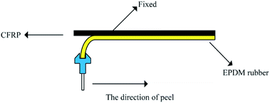 |
| | Scheme 1 The schematic diagram of the 90° peel strength test. | |
The crosslink density was measured using 1H NMR spectroscopy (22 MHz, VTMR20-010V-I, China), and the magnetic field strength was 0.516 tesla. The decay of the transverse magnetization was measured with the CPMG-echo pulse sequence: 90°–t1–180°–t2 (the values of t1 and t2 were 3 μs and 7 μs, respectively). This pulse was carried out 16 times; the waiting time was 1500 ms and the final echo time was 0.05 ms. All the processes mentioned above were performed under 50 °C because under this temperature, the magnetic field inhomogeneity can be eliminated for precise and quantitative measurements.
Thermogravimetric analysis (TGA) was performed with a thermo-gravimetric analyser (TA instrument Q500, America). The samples were measured under an air atmosphere by heating from 25 to 800 °C. The heating rate was 10 °C min−1 to study the thermal stability of the EPDM/CFRP composite.
The ILSS test was carried out on a universal testing machine (5500R, Instron, USA). The specimen dimensions for the ILSS test were 200 mm × 6.5 mm × 2 mm. The ILSS test was carried out at a cross-head speed of 2 mm min−1. The ILSS data were the average of 5 specimens.
Results and discussion
The adhesive strength of CFRP/EPDM
Fig. 1(a–c) show the peel force as a function of time for the independently cured samples. However, from Fig. 1, we can see that when bonded with CFRP using the independent method, the EPDM rubbers cured by different vulcanization systems represent extremely low peel forces and a stable state does not appear, which also means that there is no valid adhesive layer between CFPR and EPDM. Thus, we could not calculate the average peel strength. Fig. 2 can also explain this situation and the independently cured system will not be discussed.
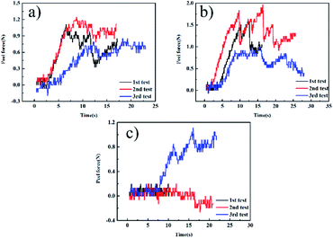 |
| | Fig. 1 The 90° peel strength curves of the independent samples: (a) CFRP/EPDM-DCP, (b) CFRP/EPDM-S, and (c) CFRP/EPDM-TAIC. | |
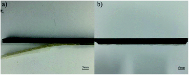 |
| | Fig. 2 The photographs of (a) independently CFRP/EPDM and (b) co-curing CFRP/EPDM. | |
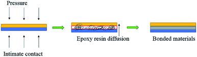
Fig. 3(a–c) show the peel force as a function of time for the co-curing samples. The maximum peel forces of different cured systems are slightly different. However, we found that during the peeling process, the peel force declined sharply and recovered slowly to a stable level because of the presence of air in the EPDM rubber. When EPDM was peeled from CFRP, the air in the EPDM rubber may reach the stress concentration point to damage the rubber in advance. However, at this moment, the EPDM did not break completely; thus, the peel force could regain a normal level. When calculating the average peel strength of different samples, the unstable stage at an earlier time should be excluded in order to ensure the vitality of the data. The real peel strength is recorded as the average peel force of three entries divided by the width of the strip of the soft material. As shown in Fig. 3d, the peel strengths of CFRP/EPDM-DCP, CFRP/EPDM-DCP-S, and CFRP/EPDM-DCP-TAIC are 2.791 N mm−1, 2.888 N mm−1, and 3.088 N mm−1, respectively, all of which are much better than the data in Fig. 1. As we all know, according to the adhesive theory,30 the smaller the polarity, the harder the wetting. The polarity of EPDM is much lower than that of the epoxy resin used as the adhesive in the independent method. In terms of the adhesive theory, only materials with higher surface energy can be wetted by materials with lower surface energies.31 However, using the co-curing method, as shown in Scheme 2, there was intimate contact between CFRP and EPDM under pressure, the result of which was that the epoxy resin may diffuse into EPDM before being hardened to form a mixing layer, thus providing good adhesive strength. Additionally, we will confirm the presence of the mixing layer using SEM analysis.
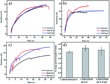 |
| | Fig. 3 The 90° peel strength curves of the co-curing samples: (a) CFRP/EPDM-DCP, (b) CFRP/EPDM-S, and (c) CFRP/EPDM-TAIC. (d) The average peel strength of different co-curing systems. | |
 |
| | Scheme 2 Illustration of the co-curing process.32 | |
SEM of CFRP/EPDM composite
From the SEM images of CFRP/EPDM provided in Fig. 4, it is evident that in CFRP, the epoxy resin and CFs achieve a relatively good wetting degree mainly because of the existence of the sizing agents on the fiber. However, a clear mixing layer can be observed between CFRP and EPDM, which can explain the good adhesive strength between CFRP and EPDM, as mentioned above, although the polarity of EPDM is low. The formation of the mixing layer may be due to the diffusion process of the epoxy resin, which has good fluidity at higher temperatures, before the epoxy gel process; thus, it diffuses into the EPDM rubber. After the epoxy resin cures and solidifies, the mixing layer may be strong enough to provide good adhesion between CFRP and EPDM. Besides, a very apparent delamination phenomenon can be observed (in Fig. 2b), corresponding to the gap between CFRP and the mixing layer observed in Fig. 4.
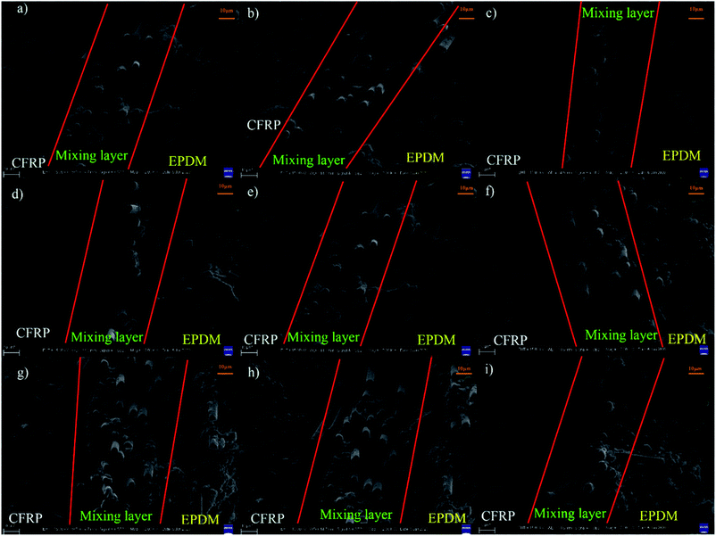 |
| | Fig. 4 SEM images of (a–c) CFRP/EPDM-DCP, (d–f) CFRP/EPDM-S and (g–i) CFRP/EPDM-TAIC. | |
Thermal stability of CFRP/EPDM composite
As inferred from the TGA analysis shown in Fig. 5, both CFRP and CFRP/EPDM possess good thermal stability under the Td of 360 °C.33 However, the residual mass of CFRP at 800 °C is 74%, which is higher than those of CFRP/EPDM-DCP, CFRP/EPDM-DCP-S, and CFRP/EPDM-DCP-TAIC (49%, 47%, and 46%, respectively). The phenomenon mentioned above may be a consequence of replacing some CFRP with EPDM rubber. As we all know, the main product of CFRP after burning is a carbon fiber, which is very stable even at 800 °C.34 From the TGA analysis, there is apparent thermal degradation between 400 °C and 500 °C, corresponding to the decomposition of the EPDM rubber. Therefore, when we replaced some CFRP with EPDM rubber, the final weight percentages of the CFRP and CFRP/EPDM systems at 800 °C were certainly different. However, the Td10% values of different samples (Fig. 5) indicated some apparent diversity. The Td10% value of CFRP/EPDM-DCP was 400 °C, which was higher than that of CFRP (388 °C). This may result from the excellent thermal stability and extremely low thermal conductivity coefficient of the EPDM rubber.35 At the same time, we also found that the Td10% value of CFRP/EPDM-DCP was higher than those of CFRP/EPDM-DCP-S and CFRP/EPDM-DCP-TAIC. From the vulcanization mechanism of peroxide, sulfur and TAIC co-agents,36,37 we already know that the major components of EPDM-DCP, EPDM-DCP-S, and EPDM-DCP-TAIC are C–C bonds (352 kJ mol−1), C–S bonds (<285 kJ mol−1) and C–Sx (<252 kJ mol−1) as well as C–N bonds (305 kJ mol−1), respectively. It is indisputable that the higher the bond energy, the better the thermal stability. Hence, the Td10% value of CFRP/EPDM-DCP was much higher than that of the other systems.
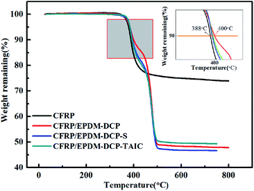 |
| | Fig. 5 The TGA curve of co-curing systems. | |
The crosslink density of EPDM rubber
According to Fig. 6, EPDM-DCP, EPDM-DCP-S, and EPDM-DCP-TAIC that vulcanized for 20 min were denominated as 1, 3, and 5, respectively. The EPDM rubber parts of CFRP/EPDM-DCP, CFRP/EPDM-DCP-S, and CFRP/EPDM-DCP-TAIC were named as 2, 4, and 6, respectively.
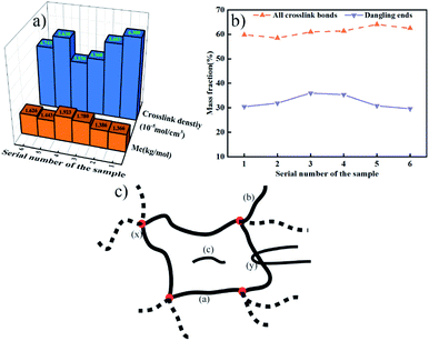 |
| | Fig. 6 (a) Crosslink density and Mc of the EPDM rubber. (b) Mass fraction of the crosslinking bonds and dangling bonds. (c) Schematic of the crosslink structure of the EPDM rubber. | |
The total crosslink density, molecular mass of crosslink (Mc), and mass fraction of all crosslinking bonds and dangling bonds are shown in Fig. 6a and b. From Fig. 6a, we can find that compared to the samples co-curing with CFRP for longer times and at higher temperatures, the EPDM rubber vulcanized at a lower temperature and shorter time possesses relatively lower Mc and better crosslink density because the crosslinking bonds have begun to dissociate under the consistently high temperature.38 In addition whatever co-curing with CFRP for higher temperature and longer time or vulcanized by a normal process, EPDM-DCP represents the lowest Mc value (the more integrated the crosslink net, the smaller the Mc) and the best crosslink density. Besides the Mc and crosslink density of EPDM-DCP-S were lower than those of EPDM-DCP as well as EPDM-DCP-TAIC, which was in agreement with the lower Td10% of EPDM-DCP. When DCP and S were added to the vulcanization system simultaneously, S could react with the macro-radicals or peroxide radicals to decrease the efficiency of vulcanization and crosslink density.18 In addition, the bond energy of C–S is much lower than those of the C–C and C–N bonds, as mentioned above; thus, the EPDM rubber cured with DCP and S demonstrates worse heat resistance. As a matter of fact, there are some differences in the mass fractions of the crosslinking bonds between different vulcanized systems. According to the structure shown in Fig. 6c, there are inter-chain crosslinks (a), dangling ends (b), sole-molecules (c), chemical crosslink points (x), and physical entanglements (y) in a rubber crosslink net.39 Fig. 6b indicates that when S and TAIC were added to the vulcanization system, the mass fractions of all crosslinking bonds increased slightly. The EPDM rubber vulcanized by the same cured system but with a totally different process exhibited virtually the same mass fraction of all crosslinking bonds and dangling ends. However, it displayed a different Mc value and crosslink density, which may be the result of physical entanglement or trapped chain entanglement.40
The ILSS of CFRP
After the EPDM rubber was peeled from CFRP, an ILSS test was carried out for the rest of CFRP to determine if the existence of the EPDM rubber in the co-curing process deteriorated the mechanical properties of CFRP. The ILSS data are shown in Fig. 7. The ILSS values of CFRP, CFRP-EPDM-DCP, CFRP-EPDM-DCP-S, and CFRP-EPDM-DCP-TAIC were 92.79 MPa, 89.69 MPa, 93.18 MPa, and 94.17 MPa, respectively. Further inspection revealed that although EPDM had a low thermal conductivity coefficient, the mechanics of CFRP were not influenced by the lack of heat transfer in the co-curing process due to the presence of EPDM, which may contribute to the low degree of curing of epoxy.
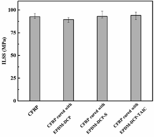 |
| | Fig. 7 The ILSS tests of different CFRPs. | |
Conclusions
In this study, a one-step co-curing method, which was different from the conventional approaches, was employed to successfully prepare a CFRP/EPDM composite. The co-curing composite system presented good thermal and mechanical properties because the crosslink density of EPDM and the ILSS of CFRP in the co-curing system were similar to those of the samples cured independently, which could guarantee excellent applications of the CFRP/EPDM composite. More importantly, good adhesive strength was achieved between CFRP and the EPDM rubber, as shown in the 90° peel strength test, even though the polarity of EPDM is very low. Additionally, the adhesive mechanism of the CFRP/EPDM composite may involve the diffusion of the epoxy resin into EPDM before the gel process. Under high temperatures and pressures, the epoxy resin was more likely to diffuse into EPDM to form a mixing layer of a certain thickness, providing good bonding strength between CFRP and EPDM; the existence of the mixing layer was also proved by SEM analysis. Besides, the co-curing method can be considered as a general way to fabricate thermosetting resins and low-polarity rubber composites. Versatile properties of the rubber in this hybrid system can be obtained by adding different kinds of additives without the concern of the polarity decrease of rubber that leads to poor adhesive strength.
Conflicts of interest
There are no conflicts to declare.
Acknowledgements
This work was financially supported by the National Natural Science Foundation of China (No. 51873048) and National Natural Science Foundation of China (No. 51903066).
Notes and references
- Q. X. Li, J. S. Church, M. Naebe and B. L. Fox, Carbon, 2016, 109, 74–86 CrossRef CAS.
- A. R. Jones, A. Cintora, S. R. White and N. R. Sottos, ACS Appl. Mater. Interfaces, 2014, 6, 6033–6039 CrossRef CAS PubMed.
- X. S. Huang and B. Patham, J. Appl. Polym. Sci., 2013, 127, 1959–1966 CrossRef CAS.
- P. Bajpai and M. Bajpai, Pigm. Resin Technol., 2010, 39, 96–100 CrossRef CAS.
- A. K. Pathak, M. Borah, A. Gupta, T. Yokozeki and S. R. Dhakate, Compos. Sci. Technol., 2016, 135, 28–38 Search PubMed.
- Z. J. Wu, H. Y. Cui, L. Chen, D. W. Jiang, L. Weng, Y. Y. Ma, X. J. Li, X. H. Zhang, H. Liu, N. Wang, J. X. Zhang, Y. Ma, M. Y. Zhang, Y. D. Huang and Z. H. Guo, Compos. Sci. Technol., 2018, 164, 195–203 CrossRef CAS.
- C. Ding and A. S. Matharu, ACS Sustainable Chem. Eng., 2014, 2, 2217–2236 CrossRef CAS.
- F. L. Jin, X. Li and S. J. Park, J. Ind. Eng. Chem., 2015, 29, 1–11 CrossRef CAS.
- E. A. Baroncini, S. K. Yadav, G. R. Palmese and J. F. Stanzione, J. Appl. Polym. Sci., 2016, 133, 44103 CrossRef.
- F. Ferdosian, Z. S. Yuan, M. Anderson and C. B. Xu, Thermochim. Acta, 2015, 618, 48–55 CrossRef CAS.
- E. A. Snijders, A. Boersma, B. van Baarle and J. Noordermeer, Polym. Degrad. Stab., 2005, 89, 200–207 CrossRef CAS.
- M. Van Duin and H. G. Dikland, Rubber Chem. Technol., 2003, 76, 132–144 CrossRef CAS.
- R. A. Orza, P. C. M. M. Magusin, V. M. Litvinov, M. van Duin and M. A. J. Michels, Macromolecules, 2009, 42, 8914–8924 CrossRef CAS.
- S. Singh, P. K. Guchhait, G. G. Bandyopadhyay and T. K. Chaki, Composites, Part A, 2013, 44, 8–15 CrossRef CAS.
- D. Jia, J. Zheng, X. Chen and J. Q. Yu, J. Adhes., 2017, 93, 481–503 CrossRef CAS.
- D. J. Haloi, K. Naskar and N. K. Singha, Eur. Polym. J., 2013, 49, 4098–4107 CrossRef CAS.
- M. Akiba and A. S. Hashim, Prog. Polym. Sci., 1997, 22, 475–521 CrossRef CAS.
- J. Kruzelak, R. Sykora and I. Hudec, Chem. Pap., 2016, 70, 1533–1555 CAS.
- L. Gonzalez, A. Rodriguez, J. L. Valentin, A. Marcos-Fernandez and P. Posadas, KGK, Kautsch. Gummi Kunstst., 2005, 58, 638–643 CAS.
- M. Sureshkumar, C. Bhuvaneswari, S. Kakade and M. Gupta, Polym. Adv. Technol., 2008, 19, 144–150 CrossRef CAS.
- Q. C. Zhou, J. S. Xu, X. Chen and C. S. Zhou, J. Adhes., 2016, 92, 402–428 CrossRef CAS.
- H. M. Chen, R. G. Lv, P. Liu, H. Y. Wang, Z. Y. Huang, T. Huang and T. S. Li, J. Appl. Polym. Sci., 2013, 128, 1592–1600 CAS.
- B. S. Gupta and M. P. G. Laborie, J. Adhes., 2007, 83, 939–955 CrossRef CAS.
- S. Deng, L. Djukic, R. Paton and L. Ye, Composites, Part A, 2015, 68, 121–132 Search PubMed.
- H. Shi, J. Sinke and R. Benedictus, Int. J. Adhes. Adhes., 2017, 73, 51–57 Search PubMed.
- A. Streitferdt, N. Rudolph and I. Taha, Appl. Compos. Mater., 2017, 24, 1137–1149 Search PubMed.
- E. Sarlin, E. Heinonen, J. Vuorinen, M. Vippola and T. Lepisto, Int. J. Adhes. Adhes., 2014, 49, 51–57 CrossRef CAS.
- J. Zhu, J. D. Kim, H. Q. Peng, J. L. Margrave, V. N. Khabashesku and E. V. Barrera, Nano Lett., 2003, 3, 1107–1113 CrossRef CAS.
- Y. Leng, M. J. Xu, Y. Sun, R. X. Han and B. Li, Polym. Adv. Technol., 2019, 30, 2468–2479 Search PubMed.
- R. D. Adams, Handbook of Adhesion Technology, Springer Berlin Heidelberg, 2011 Search PubMed.
- P. S. Panesar and J. F. Kennedy, Carbohydr. Polym., 2006, 64, 480–482 Search PubMed.
- F. Yang and R. Pitchumani, Polym. Eng. Sci., 2002, 42, 424–438 CrossRef.
- N. Phonthammachai, X. Li, S. Wong, H. L. Chia, W. W. Tjiu and C. B. He, Composites, Part A, 2011, 42, 881–887 CrossRef.
- A. K. Pathak, H. Garg, M. Singh, T. Yokozeki and S. R. Dhakate, J. Polym. Res., 2019, 26, 23 CrossRef.
- A. F. Ahmed and S. V. Hoa, J. Compos. Mater., 2012, 46, 1549–1559 CrossRef.
- G. Heideman, J. W. M. Noordermeer, R. N. Datta and B. van Baarle, Rubber Chem. Technol., 2005, 78, 245–257 CrossRef CAS.
- K. F. El-Nemr, Mater. Des., 2011, 32, 3361–3369 CrossRef CAS.
- I. S. Han, C. B. Chung and J. W. Lee, Rubber Chem. Technol., 2000, 73, 101–113 CrossRef CAS.
- U. Heuert, M. Knorgen, H. Menge, G. Scheler and H. Schneider, Polym. Bull., 1996, 37, 489–496 CrossRef CAS.
- R. A. Orza, P. C. M. M. Magusin, V. M. Litvinov, M. van Duin and M. A. J. Michels, Macromol. Symp., 2005, 230, 144–148 CrossRef CAS.
Footnote |
| † These authors contributed equally to this work. |
|
| This journal is © The Royal Society of Chemistry 2020 |
Click here to see how this site uses Cookies. View our privacy policy here. 
 Open Access Article
 This Open Access Article is licensed under a Creative Commons Attribution-Non Commercial 3.0 Unported Licence
 a,
XiaoTong Yi†a,
YongJian Xionga,
XinJing Weia,
YaDong Wu
a,
XiaoTong Yi†a,
YongJian Xionga,
XinJing Weia,
YaDong Wu


