
 Open Access Article
 This Open Access Article is licensed under a Creative Commons Attribution-Non Commercial 3.0 Unported Licence
Characterization and simulation study of organic solar cells based on donor–acceptor (D–π–A) molecular materials
Anass El Karkri *a,
Zakaria El Malki*a,
Mohammed Bouachrineb,
Françoise Serein-Spirauc and
Jean-Marc Sotiropoulosd
*a,
Zakaria El Malki*a,
Mohammed Bouachrineb,
Françoise Serein-Spirauc and
Jean-Marc Sotiropoulosd
aMoulay Ismaïl University, MEM, High School of Technology (ESTM), B.P 3103 Toulal, 50040 Meknes, Morocco. E-mail: anass.elkarkri@gmail.com; z.elmalki@est.umi.ac.ma
bMoulay Ismaïl University, Faculty of Sciences Meknes, Morocco
cMolecular and Macromolecular Heterochimy, UMR, CNRS 5076, Higher National School of Chemistry, Montpellier, France
dPau and Adour Countries University, UMR5254 – IPREM, Chemistry-Physics Team, Helioparc Pau, France
First published on 18th May 2020
Abstract
In this study, the analysis of microelectronic and photonic structure in a one dimension program [AMPS-1D] has been successfully used to study organic solar cells. The program was used to optimize the performance of organic solar cells based on (carbazole-methylthiophene), benzothiadiazole and thiophene [(Cbz-Mth)-B-T]2 as electron donors, and [6,6]-phenyl-C61-butyric acid methyl ester (PCBM) as an electron acceptor. The optoelectronic properties of these dyes were investigated by using the Density Functional Theory DFT/B3LYP/6-31G(d,p) method. We studied the influence of the variation of the thickness of the active layer, the temperature, and the density of the effective states of the electrons and the holes in the conduction and valence bands respectively on the performance of the solar cells based on [(Cbz-Mth)-BT]2–PCBM as a photoactive material, sandwiched between a transparent indium tin oxide (ITO) and an aluminum (Al) electrode. The addition of other thiophene units in the copolymer or the deposition of a layer of PEDOT between the anode (ITO) and the active layer, improves the performances of the cell, especially resulting in a remarkable increase in the value of the power conversion efficiency (PCE).
Introduction
Nowadays, marketed solar cells are largely based on silicon. The purification processes of this material, using advanced technologies and intensive temperature, makes the purchase price inaccessible to most ordinary people.1 Small-molecule-based organic semiconductors are expected to open new possibilities in terms of optoelectronic applications in organic electronic devices including organic light-emitting diodes (OLEDs), organic solar cells (OSCs), and field effect transistors (FETs). Nevertheless, the lower efficiency of OLEDs and OSCs has seriously restricted their commercialization. The development of new small molecular materials with highly desirable properties remains a major challenge. Much research has focused on the study of new conductive materials that are easily achievable, and relatively easy to produce at low cost.2–5The interaction between electron donors (D) and electron acceptors (A) in a copolymer may result in hybridization of the highest occupied molecular orbital (HOMO) of the donor and the lowest unoccupied molecular orbital (LUMO) of the acceptor, leading to an organic semiconductor with low gap energy. In order to increase the efficiency of energy conversion of the photovoltaic device, by improving exciton charge transfer and transport, several conjugated polymers consisting of alternating donor (D) and acceptor (A) with a low gap energy have been developed.6–10 The power conversion efficiency (PCE) of lab-scale organic photovoltaic (OPV) devices has reached up to 8–10% (ref. 11 and 12) through the development of novel donor materials and meticulous device optimization, indicating a bright future for OPV devices in commercial applications. In this work, the AMPS-1D program is used to study and simulate the optimal performance of organic solar cells, based on organic material composed of a donor material: (carbazole-methylthiophene), benzothiadiazole, dithiophene, and an acceptor material: [6,6]-phenyl-C61-butyric acid methyl ester (PCBM).13 The optimized structures (Fig. 1) and optoelectronic properties of these dyes6 were investigated by using the Density Functional Theory DFT/B3LYP/6-31G(d,p) method set on the Gaussian 09 software package. In the first part, we will study the influence of the thickness of the active layer, the temperature, the effective state density of electrons and holes, and the insertion of the thiophene units in the donor material on the performance of the solar cells. In the second phase, we will study the influence of the addition of a PEDOT layer between the anode and the active layer (made of [(Cbz-Mth)-BT]2–PCBM) material on the performance of a photovoltaic solar cell.
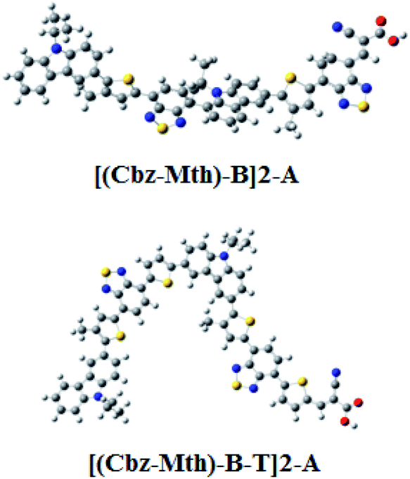 | ||
| Fig. 1 Optimized structures obtained by B3LYP/6-31G(d,p) of the studied molecules. | ||
Computational details
DFT calculation
The molecular calculations were performed in the gas phase using Density Functional Theory (DFT) with the B3LYP hybrid functional.14–16 Using the 6-31G(d,p) basis set on the Gaussian 09 software package, all optimizations were calculated without any symmetry constraints.17 The HOMO, LUMO and gap (ΔHOMO–LUMO) energies are also deduced for the stable structures. We investigated the localization of the frontier orbitals. The spatial distribution of frontier orbitals HOMO and LUMO allows us to understand the photovoltaic properties of solar cells.AMPS-1D program
We can use computer models as a method that leads to better design of the device. Device modeling implies the numerical solution of a set of equations, which form a mathematical model for device operation. The reliability of the input parameters required by the internal numerical models influences the usefulness of the simulation results. The advantage of using simulation programs is the possibility of examining the influence of the parameters of the model, which cannot be determined experimentally. The one-dimensional device simulation program AMPS solves the Poisson equation and the electron and hole continuity equations by using the method of finite differences and the Newton–Raphson technique (Pennsylvania State University, 1997).Description of the organic solar cells structure
In this work, we outline a theoretical study of the photovoltaic properties of new molecular materials based on carbazole (Cbz), methylthiophene (Mth), benzothiadiazole (B), and thiophene (T) [(Cbz-Mth)-B-T]2 units. The acceptor material used is PCBM.18,19 PCBM has been widely used, particularly in combination with P3HT, because of its high electron mobility and remarkable electronic conductivity.20 For the purposes of the simulation, we have schematized the active layer of the bulk heterojunction (BHJ) solar cells.21–27 The structure is shown in Fig. 2. The structure consists of: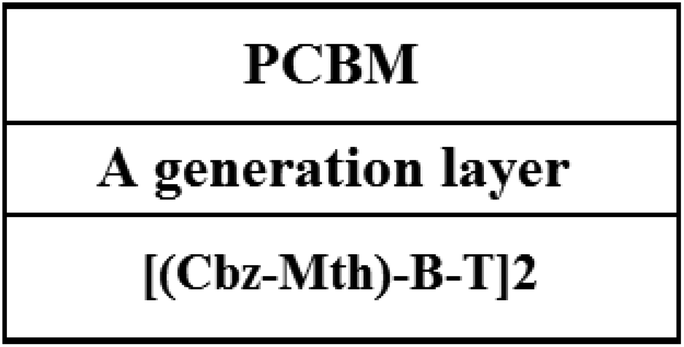 | ||
| Fig. 2 Scheme of the organic cell (BHJ) based on PCBM and [(Cbz-Mth)-B-T]2. | ||
• An acceptor layer (PCBM).
• A generation layer.
• A donor layer [(Cbz-Mth)-B-T]2.
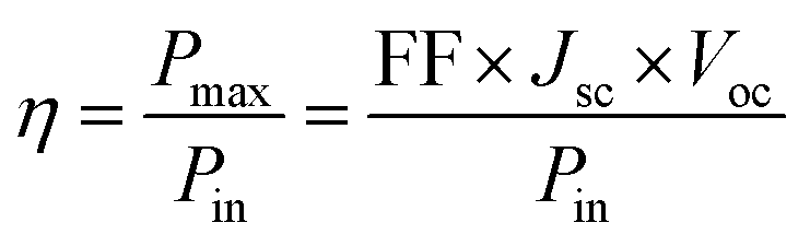
The power conversion efficiency (η) was calculated according to eqn (1).28
 | (1) |
 | (2) |
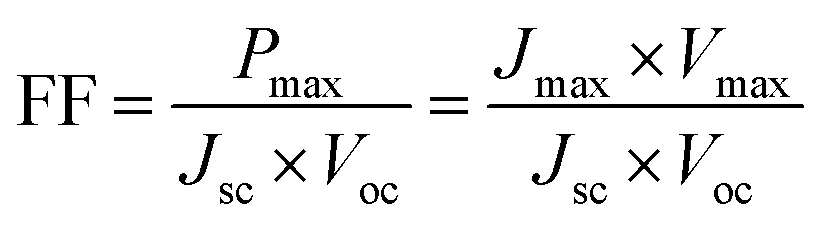
The fill factor can also provide information on the quality of the material–electrode interfaces. The theoretical values of open-circuit voltage Voc were calculated from the following expression:29
| Voc = |EdonorHOMO − EacceptorLUMO| | (3) |
The maximum conversion efficiency of a cell has significance that is limited to a given spectral distribution and intensity. The standard illumination most commonly used, and that which will be systematically used in this work, and which corresponds to an air mass coefficient is AM1.5.30
PCEs in the range of 6–10% were achieved in recent years for a single BHJ solar cell31–36 and a PCE of 10.1% (ref. 37) and 12% for tandem cell devices.38
Modeling of an organic solar cell
The photovoltaic solar cell is modeled by the equivalent circuit shown in Fig. 3.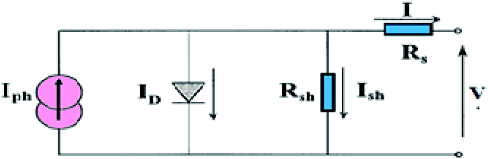 | ||
| Fig. 3 Equivalent circuit of the photovoltaic cell. | ||
A photovoltaic cell in the dark behaves like a classical diode. It abides by the Shockley’s law:
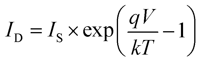 | (4) |
Under illumination, taking into account the photo-current generated (Iph), we obtain the following equation:
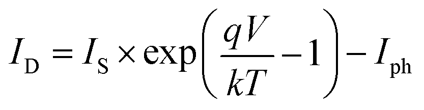 | (5) |
Series Rs and shunt Rsh resistances
The series resistance Rs characterizes the voltage losses in the semiconductor and through the ohmic contacts of the cell. It reports the resistivity of the material, that of the electrodes and the semiconductor–metal contact. The shunt resistance Rsh reflects the presence of leakage current in the diode due to the recombination of the carriers in the vicinity of the charge dissociation sites (at the D/A interface and at the electrodes) and to the possible existence of a leak initiated by geometric inhomogeneities of the layers.39• The slope of the curve J(V) at the point Voc represents the inverse of the series resistance 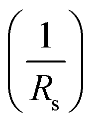 .
.
• The slope of the curve J(V) at the point Jsc represents the inverse of the shunt resistance  .
.
Results and discussion
Electronic properties
The energy gaps (Egap) for [(Cbz-Mth)-B]2-A, [(Cbz-Mth)-B-T]2-A, [(Cbz-Mth)-B-DT]2-A and [(Cbz-Mth)-B-TT]2-A obtained by the differences of HOMO and LUMO energy levels (ΔHOMO–LUMO) using B3LYP/6-31G(d,p) are shown in Fig. 4. The insertion of thiophene as aspacer unit in the backbone copolymer leads to some structural and optical changes. The band gaps in the case of the [(Cbz-Mth)-B-T]2-A, [(Cbz-Mth)-B-DT]2-A and [(Cbz-Mth)-B-TT]2-A copolymers are about 1.77 eV, 1.70 eV and 1.74 eV respectively which are lower by about 0.22 eV, 0.29 eV and 0.25 eV compared to [(Cbz-Mth)-B]2-A.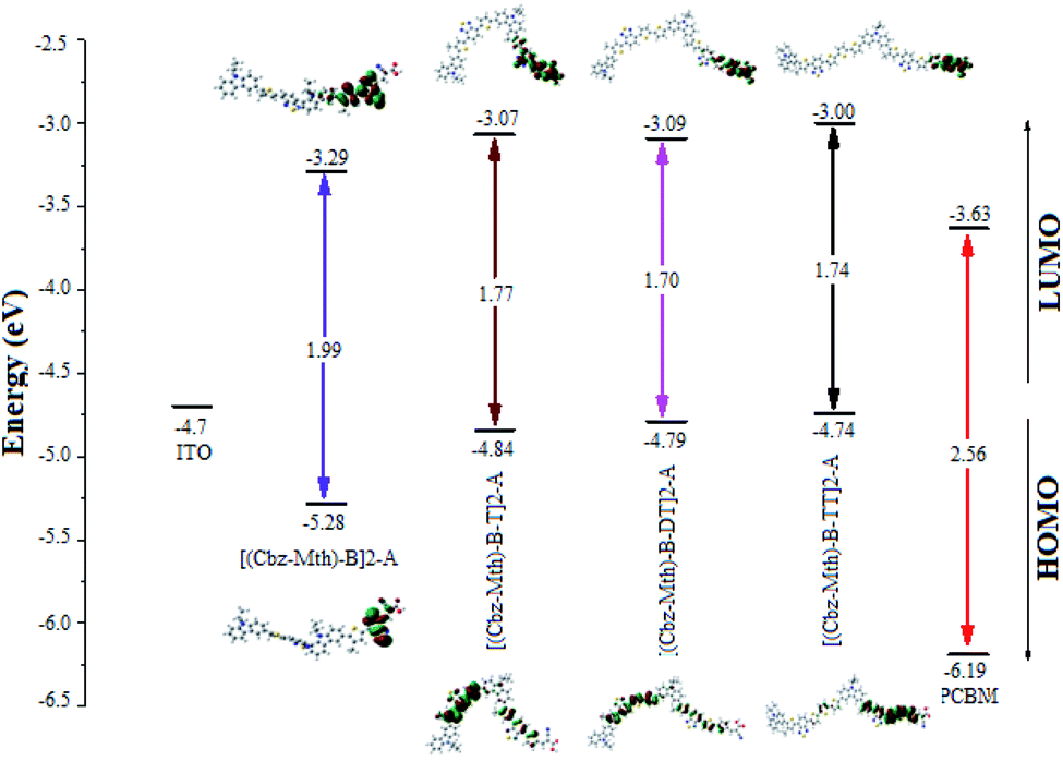 | ||
| Fig. 4 The sketch of B3LYP/6-31G(d,p) calculated energies of the HOMO and LUMO level and the contour plots of HOMO and LUMO orbitals of the studied molecules.6 | ||
The contour plot of the HOMO and LUMO orbitals of the studied oligomers obtained by B3LYP/6-31G(d,p) is shown in Fig. 4. The electronic transitions from HOMO to LUMO for the molecules studied could lead to an intramolecular charge transfer from donor units to anchoring groups via the conjugated system, because a strong localization of the HOMOs occurs on the donor subunits of the polymer backbone, in particular on the thiophene units, and a strong delocalization of LUMOs occurs on the bridges between subunits showing the flow of electron density along the polymer backbone. The electronic density of LUMO is mainly located on the acceptor units (mostly in the anchor group).
Influence of the thickness
For a fixed temperature (300 K), we will study the impact of the thickness on the properties of the active layer of the organic solar cell based on [(Cbz-Mth)-B-T]2–PCBM (Fig. 5). To do so, we will vary the thickness of the active layer from 60 to 200 nm.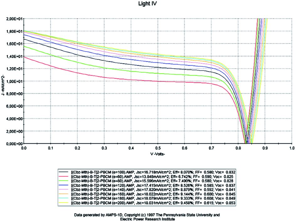 | ||
| Fig. 5 Simulation by AMPS-1D of the characteristics J(V) of the organic solar cell based on [(Cbz-Mth)-B-T]2–PCBM for different thicknesses. | ||
The results of the simulation are shown in Table 1.
| Thickness (nm) | Jsc (mA cm−2) | Voc (V) | FF | η% | Rsh (Ω cm2) | Rs (Ω cm2) |
|---|---|---|---|---|---|---|
| 60 | 13.848 | 0.825 | 0.590 | 6.742 | 68.39 | 3.5 |
| 80 | 15.596 | 0.828 | 0.580 | 7.490 | 71.48 | 3.44 |
| 100 | 16.718 | 0.832 | 0.580 | 8.070 | 75.36 | 3.36 |
| 120 | 17.415 | 0.837 | 0.585 | 8.526 | 80.91 | 3.26 |
| 140 | 17.820 | 0.841 | 0.592 | 8.879 | 85.91 | 3.18 |
| 160 | 18.022 | 0.845 | 0.600 | 9.144 | 99.45 | 3.10 |
| 180 | 18.079 | 0.849 | 0.608 | 9.333 | 103.54 | 3.02 |
| 200 | 18.031 | 0.853 | 0.615 | 9.458 | 116.06 | 2.94 |
Based on the obtained results, we present the parameters of the photovoltaic cell versus thickness (Fig. 6).
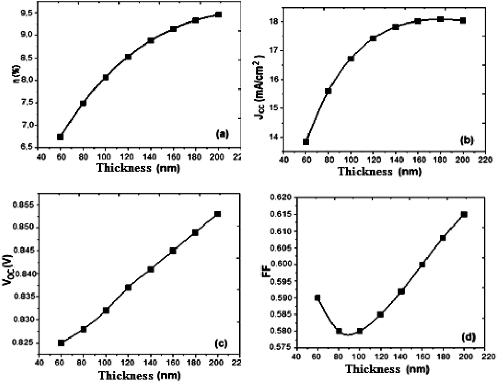 | ||
| Fig. 6 Variation of (a) conversion efficiency η%, (b) short-circuit current density Jsc, (c) open-circuit voltage Voc, and (d) fill factor versus thickness active layer. | ||
Drawing on the results obtained, it is inferred that the values of the conversion efficiency increase with the increase of the thickness of the active layer; this is due mainly to the better absorption of the thicker layers, since the absorption of the light is one of the determining factors of photovoltaic efficiency. On the other hand, the development of active layers with a thickness greater than 200 nm, poses numerous technical problems, which inevitably generate higher costs. Between 60 and 180 nm, the density of the short-circuit current density Jsc increases with the increase of the thickness of the active layer, and from 140 nm the density value becomes constant, and the open-circuit voltage Voc follows slightly the increase in thickness, while the fill factor FF decreases between 60 and 100 nm and slightly increases between 120 and 200 nm. On the other hand, if we compare our results obtained by simulation with those obtained in the case of P3HT/PCBM, we notice an improvement in the performance of the solar cell.
The results show that the optimum efficiency for [(Cbz-Mth)-B-T]2/PCBM is at 120 nm thickness. The experimental results give an optimum thickness of about 100 nm (Popescu, 200840). We also notice that the value of the resistance Rsh increases strongly. It reaches a value of 116.06 (Ω cm2) for a thickness of 200 nm. On the other hand, the value of the resistance Rs decreases.
Effect of the temperature
In this part, the temperature is varied and the value of the active layer thickness remains constant at 100 nm (Fig. 7).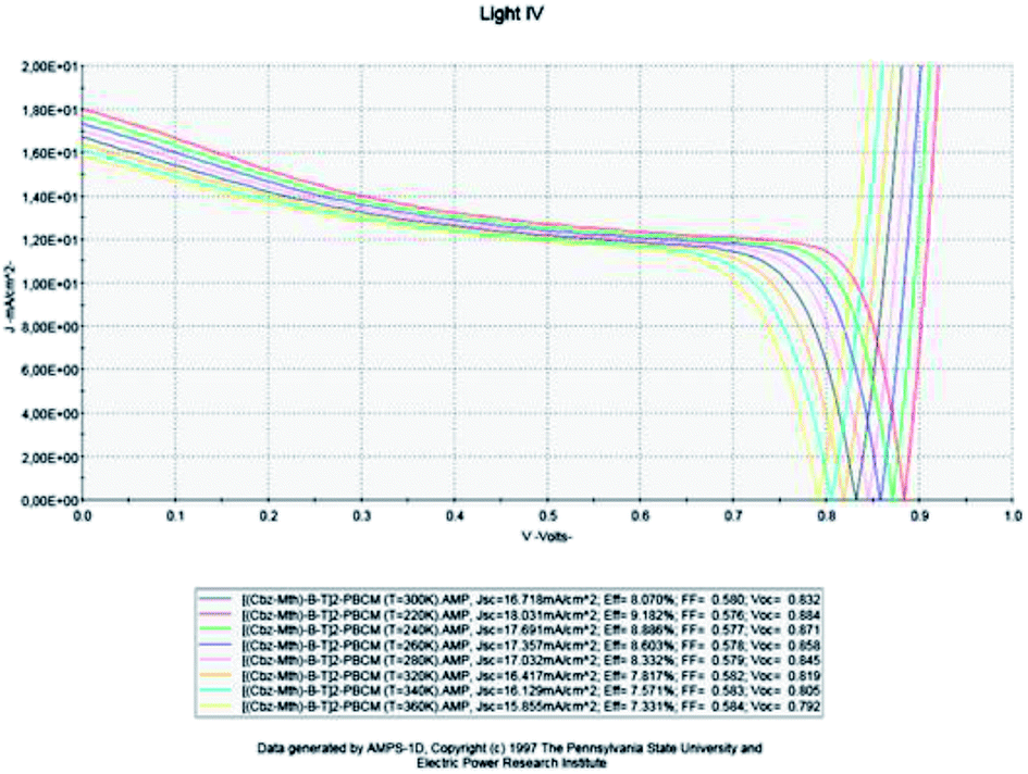 | ||
| Fig. 7 Simulation by AMPS-1D of the characteristics J(V) of the organic solar cell based on [(Cbz-Mth)-B-T]2–PCBM for different temperatures. | ||
The results of the simulation are shown in Table 2.
| Temperature (K) | Jsc (mA cm−2) | Voc (V) | FF | η% | Rsh (Ω cm2) | Rs (Ω cm2) |
|---|---|---|---|---|---|---|
| 220 | 18.031 | 0.884 | 0.576 | 9.182 | 85.39 | 4.16 |
| 240 | 17.691 | 0.871 | 0.577 | 8.886 | 81.57 | 3.90 |
| 260 | 17.357 | 0.858 | 0.578 | 8.603 | 77.91 | 3.62 |
| 280 | 17.032 | 0.845 | 0.579 | 8.332 | 75.91 | 3.36 |
| 300 | 16.718 | 0.832 | 0.580 | 8.070 | 75.36 | 3.10 |
| 320 | 16.417 | 0.819 | 0.582 | 7.817 | 70.93 | 2.84 |
| 340 | 16.129 | 0.805 | 0.583 | 7.571 | 70.28 | 2.58 |
| 360 | 15.855 | 0.792 | 0.584 | 7.331 | 69.78 | 2.32 |
Based on results obtained by the simulation, we can trace the characteristics of the photovoltaic cell parameters according to the temperature (Fig. 8).
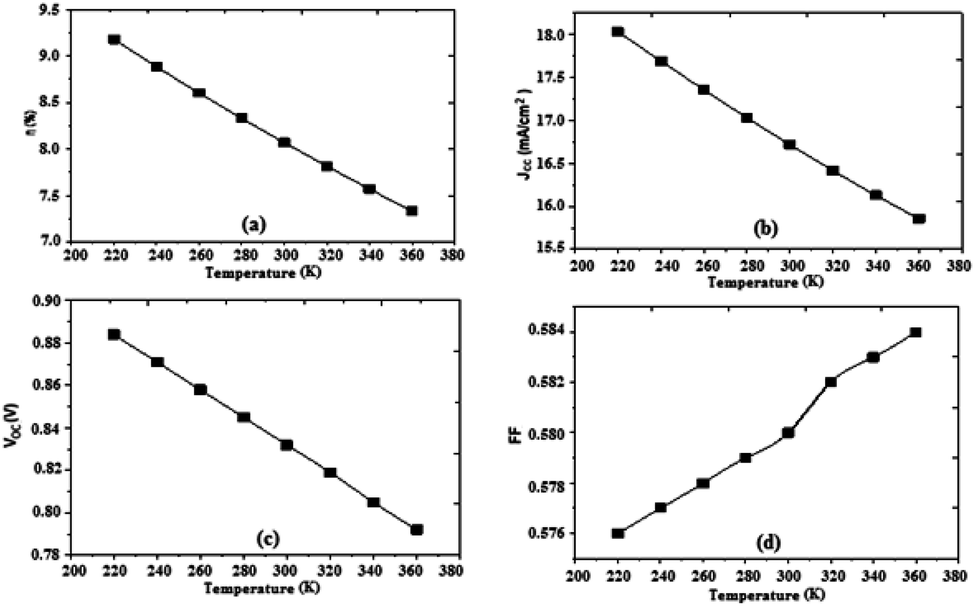 | ||
| Fig. 8 Variation of (a) conversion efficiency η%, (b) short-circuit current density Jsc, (c) open-circuit voltage Voc, and (d) fill factor as a function of temperature. | ||
The temperature has a certain influence on the performances of the organic cell; we notice a decrease in several parameters of the cell (η, Jsc, Voc) with the increase of the temperature, while the fill factor FF increases slightly with increasing temperature. However, the impact of the change in temperature on the open circuit voltage Voc in organic cells is significantly less than that observed in inorganic cells, where it was observed that the open circuit voltage decreases by increasing the temperature (2.3 mV K−1), implying a significant advantage of organic photovoltaic cells in many fields of use. The efficiency decreased to a value of 7.33%, Fig. 8. The results show that the optimum efficiency is at 8.07% for 300 K. The optimum theoretical efficiency reported in the literature is about 8% (Koster et al., 2006).41 The values of the resistances Rsh and Rs decrease with the decrease of the temperature.
Effect of the effective state density of electrons and holes in the conduction and valence bands, respectively
The solar cell has a thickness of 100 nm and the temperature is fixed at 300 K. We vary the density of the effective states of electrons and holes in the conduction and valence bands respectively. The results of the simulation are shown in Fig. 9 below.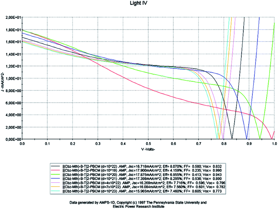 | ||
| Fig. 9 Simulation by AMPS-1D of the characteristics J(V) of the organic solar cell based on [(Cbz-Mth)-B-T]2–PCBM for different effective densities. | ||
The results of the simulation are shown in Table 3.
| Density (cm−3) | Jsc (mA cm−2) | Voc (V) | FF | η% | Rsh (Ω cm2) | Rs (Ω cm2) |
|---|---|---|---|---|---|---|
| 1019 | 17.900 | 0.990 | 0.235 | 4.159 | 68.96 | 7.14 |
| 1020 | 17.875 | 0.943 | 0.413 | 6.955 | 69.56 | 4.75 |
| 1021 | 17.398 | 0.890 | 0.536 | 8.295 | 74.10 | 3.66 |
| 1022 | 16.718 | 0.833 | 0.580 | 8.070 | 75.36 | 3.36 |
| 4 × 10²² | 16.269 | 0.796 | 0.596 | 7.716 | 75.90 | 2.55 |
| 7 × 10²² | 16.084 | 0.782 | 0.601 | 7.560 | 81.06 | 1.97 |
| 1023 | 15.965 | 0.773 | 0.605 | 7.460 | 84.31 | 1.09 |
Based on the obtained results, we can present the characteristics of the photovoltaic cell parameters as a function of the effective state density of the electrons and the holes in the conduction and valence bands, respectively (Fig. 10).
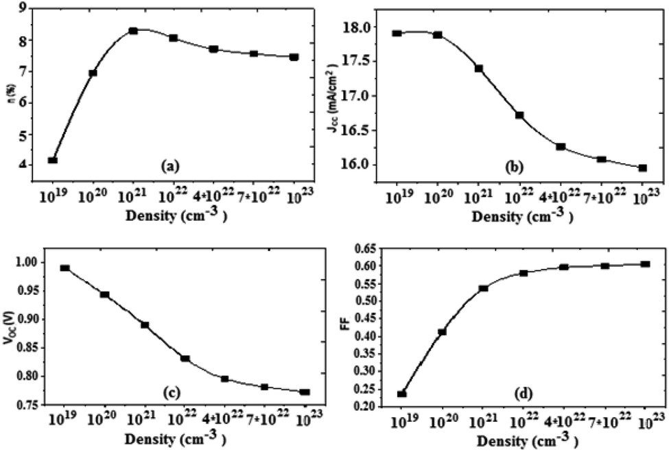 | ||
| Fig. 10 Variation of (a) conversion efficiency η%, (b) short-circuit current density Jsc, (c) open-circuit voltage Voc, and (d) fill factor as a function of density. | ||
For an increase in the effective density, the value of the current density Jsc decreases, the open circuit voltage Voc also decreases, and the fill factor increases. From the value of 1022 cm−3 the fill factor value becomes constant. It should also be noted that the increase of the effective density causes an increase in the value of the PCE, it reaches a maximum value for 1022 cm−3, and from this value the PCE decreases slightly. We also note that, as the density increases, the value of Rsh increases, and on the other hand the value of Rs decreases. The optimum value obtained for the effective density is about 1022 cm−3.
Influence of the insertion of the thiophene unit
At this stage, we examined the influence of the thiophene unit inserted in the [(Cbz-Mth)-B-T]2 copolymer on the parameters of the cell; we studied two new copolymers [(Cbz-Mth)-B-DT]2 and [(Cbz-Mth)-B-TT]2 with a gap energy of 1.70 eV and 1.74 eV respectively. In this phase we kept the same parameters used in the previous numerical simulation. We will take the value of thickness equal to 100 nm, set the temperature value at 300 K and the effective state density of electrons and holes equal to 1022 cm−3. The results of the simulation are shown in Fig. 11.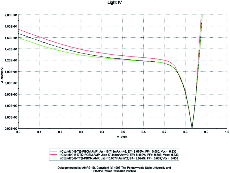 | ||
| Fig. 11 AMPS-1D simulation of the J(V) characteristics of the organic solar cell for a single, double and triple thiophene unit. | ||
For a thickness of 100 nm and a temperature of 300 K, the results obtained by the simulation are shown in Table 4.
| Copolymers | Jsc (mA cm−2) | Voc (V) | FF | η% | Rsh (Ω cm2) | Rs (Ω cm2) |
|---|---|---|---|---|---|---|
| [(Cbz-Mth)-B-T]2–PCBM | 16.718 | 0.832 | 0.580 | 8.070 | 75.36 | 3.36 |
| [(Cbz-Mth)-B-DT]2–PCBM | 17.444 | 0.833 | 0.583 | 8.469 | 77.59 | 2.38 |
| [(Cbz-Mth)-B-TT]2–PCBM | 15.967 | 0.833 | 0.609 | 8.094 | 80.53 | 2.78 |
Based on the obtained results, it is noted that: for the copolymer [(Cbz-Mth)-B-DT]2–PCBM, the value of the current density Jsc and the value of the PCE η are high compared to the other copolymers. On the other hand, the value of the fill factor and the value of the open circuit voltage are almost constant. So, we can conclude that the solar cell becomes more efficient when we add the thiophene units. This is due to the increase of conjugation properties and also the value of the gap energy is low for the two copolymers: [(Cbz-Mth)-B-DT]2–PCBM and [(Cbz-Mth)-B-TT]2–PCBM. The insertion of the thiophene units in the [(Cbz-Mth)-B-T]2–PCBM copolymer leads to a decrease in the value of Rs and an increase in the value of Rsh, and thus a minimization of losses.
Effect of incorporating a layer of PEDOT
We will use the following diagram for the simulation of the performances of the organic solar cell by the software AMPS-1D, after the introduction of the layer of PEDOT (Fig. 12).42–44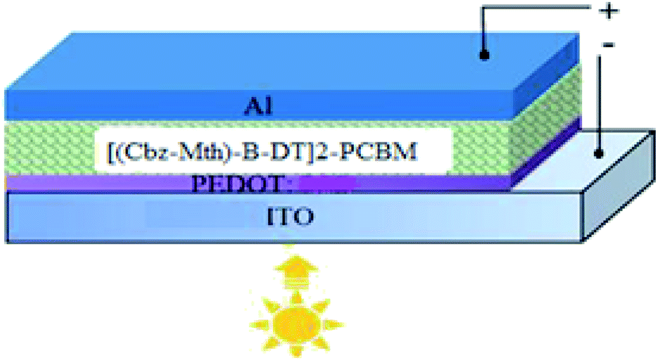 | ||
| Fig. 12 Scheme of the organic solar cell. | ||
For simulation purposes we have schematized the active layer of the BHJ structure as shown in Fig. 13. The active layer consists of:
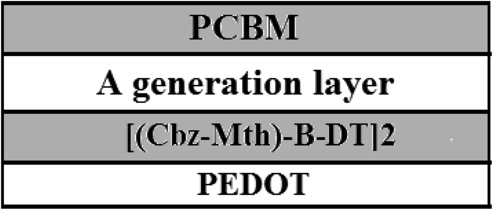 | ||
| Fig. 13 Scheme of the BHJ organic cell based on PCBM and [(Cbz-Mth)-B-DT]2 with a layer of PEDOT. | ||
• A PCBM acceptor layer.
• A generation layer.
• A donor layer [(Cbz-Mth)-B-DT]2.
• A film of PEDOT.
For a solar cell based on [(Cbz-Mth)-B-DT]2–PCBM, we introduced a layer of PEDOT and we studied the influence of this film on the performance of the cell. The results of the simulation are shown in Fig. 14.
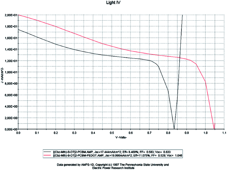 | ||
| Fig. 14 Simulation by AMPS-1D of the characteristics J(V) of the organic solar cell based on [(Cbz-Mth)-B-DT]2–PCBM before and after the incorporation of the film PEDOT. | ||
The results of the simulation are shown in Table 5.
| Copolymers | Jsc (mA cm−2) | Voc (V) | FF | η% | Rsh (Ω cm2) | Rs (Ω cm2) |
|---|---|---|---|---|---|---|
| [(Cbz-Mth)-B-DT]2–PCBM | 17.444 | 0.833 | 0.583 | 8.469 | 77.59 | 2.38 |
| PEDOT–[(Cbz-Mth)-B-DT]2–PCBM | 19.990 | 1.046 | 0.529 | 11.057 | 110 | 2.15 |
When the PEDOT layer is introduced between the anode and the active layer we noticed that the short-circuit current density value Jsc, the open circuit voltage value Voc, and the efficiency value increase. On the other hand, the value of the fill factor decreases. The results of the simulation, which are in good agreement with the literature, indicate a marked improvement in the conversion efficiency of the organic cell, following the introduction of PEDOT. The deposition of the PEDOT layer promotes the collection of the positive photo-generated charges, and prevents the diffusion of the oxygen and indium coming from the ITO towards the active layer; this explains the positive impact of the deposit on the performances of the photovoltaic device.45 Another important remark is that the value of the resistance Rsh increases strongly and the resistance Rs shows a small decrease.
Conclusions
In this work, we have simulated the performance of a photovoltaic cell based on the [(Cbz-Mth)-BT]2–PCBM copolymer using AMPS-1D software. We have studied the influence of the variation of the thickness, the temperature and the effective state density of the electrons and holes in the conduction band and the valence band. An optimization of the parameters of a solar cell is necessary to obtain a good performance. A low value of Rs and a large value of Rsh are obtained when the temperature is lowered and the thickness of the active layer is increased. We also noticed that the performance of the solar cell is improved when we inserted a thiophene unit into the material. The optimum performance for the studied solar cell obtained when the thickness is about 100 nm, the temperature 300 K and the effective state density of electrons and holes is equal to 1022 cm−3. Finally, we have concluded that a PEDOT layer inserted between the anode and the active layer has a positive impact on the performance of the organic photovoltaic cell. We found a marked improvement in the value of the efficiency, compared with other results in the literature, such as those of the poly(3-hexylthiophene) (P3HT) and [6,6]-phenyl-C61 (PCBM) cell.Conflicts of interest
The authors declare no conflicts of interest.Acknowledgements
This work has been supported by the Volubilis project AI no. MA/11/248 and by CNRST/CNRS cooperation (Project chimie 1009). We are grateful to the Association Marocaine des Chimistes Théoriciens (AMCT) for its valuable help concerning the programs. I would like also to express my thanks to Zimeng Chen, Zhitao Wang and Zhaoqian Su who helped me with AMPS-1D.References
- F. Sadiara, Etude du transport de charges dans les polymères semi-conducteurs à faible bande interdite et de son impact sur les performances photovoltaïques, Soutenue publiquement le 12 Avril 2013 Search PubMed
.
- Z. He, C. Zhong, S. Su, M. Xu, H. Wu and Y. Cao, Nat. Photonics, 2012, 6, 591–595 CrossRef
- C. E. Small, S. Chen, J. Subbiah, C. M. Amb, S.-W. Tsang, T.-H. Lai and J. R. Reynolds, Nat. Photonics, 2012, 6, 115–120 CrossRef CAS
- Handbook of Organic Conductive Molecules and Polymer, ed. H. S. Nalwa, John Wiley, New York, 1997 CrossRef CAS
- R. E. Gill, G. G. Malliaras, J. Wildeman and G. Hadziioannou, Adv. Mater., 1994, 6, 132 CrossRef CAS
- F. Garnier, G. Horowitz, X. Peng and D. Fichou, Adv. Mater., 1990, 2, 562 Search PubMed
- G. Wang, S. Qian, J. Xu, W. Wang, X. Liu, X. Lu and F. Li, Phys. B, 2000, 279, 116 CrossRef CAS
- Z. EL Malki, M. Bouachrine, F. Serein-Spirau and J.-M. Sotiropoulos, Int. J. Adv. Res. Comput. Sci. Software Eng., 2018, 8(12), 38–51 Search PubMed
- Z. El Malki, M. Bouachrine, M. Hamidi, F. Serein-Spirau, J. P. Lere-Porte and J. M. Sotiropoulos, J. Mater. Environ. Sci., 2016, 7(9), 3244–3255 CAS
- Z. EL Malki, M. Bouachrine, L. Bejjit, M. Haddad, F. Serein-Spirau and J.-M. Sotiropoulos, Int. J. Adv. Res. Comput. Sci. Software Eng., 2017, 7(6), 96–107 CrossRef
- Z. Liu, Y. Gao, J. Dong, M. Yang, M. Liu, J. Wen, Yu Zhang, H. Ma, X. Gao, W. Chen and M. Shao, J. Phys. Chem. Lett., 2018, 9, 6955–6962 CrossRef CAS PubMed
- Z. Liu, Y. Wu, Q. Zhang and X. Gao, J. Mater. Chem. A, 2016, 4, 17604 RSC
- S. Leroy-Lhez, M. Allain, J. Oberle and F. Fages, New J. Chem., 2007, 31, 1013–1021 RSC
- S. H. Vosko, L. Wilk and M. Nusair, Accurate spin-dependent electron liquid correlation energies for local spin density calculations: a critical analysis, Can. J. Phys., 1980, 58, 1200–1211 CrossRef CAS
- A. D. Becke, Density-functional thermochemistry. 3. The role of exact exchange, J. Chem. Phys., 1993, 98, 5648–5652 CrossRef CAS
- A. D. Becke, Density-functional exchange-energy approximation with correct asymptotic behavior, Phys. Rev. A, 1988, 38, 3098–3100 CrossRef CAS PubMed
- M. J. Frisch, G. W. Trucks, H. B. Schlegel, G. E. Scuseria, M. A. Robb, J. R. Cheeseman, G. Scalmani, V. Barone, B. Mennucci, G. A. Petersson, H. Nakatsuji, M. Caricato, X. Li, H. P. Hratchian, A. F. Izmaylov, J. Bloino, G. Zheng, J. L. Sonnenberg, M. Hada, M. Ehara, K. Toyota, R. Fukuda, J. Hasegawa, M. Ishida, T. Nakajima, Y. Honda, O. Kitao, H. Nakai, T. Vreven, J. A. Montgomery, J. J. E. Peralta, F. Ogliaro, M. Bearpark, J. J. Heyd, E. Brothers, K. N. Kudin, V. N. Staroverov, R. Kobayashi, J. Normand, K. Raghavachari, A. Rendell, J. C. Burant, S. S. Iyengar, J. Tomasi, M. Cossi, N. Rega, J. M. Millam, M. Klene, J. E. Knox, J. B. Cross, V. Bakken, C. Adamo, J. Jaramillo, R. Gomperts, R. E. Stratmann, O. Yazyev, A. J. Austin, R. Cammi, C. Pomelli, J. W. Ochterski, R. L. Martin, K. Morokuma, V. G. Zakrzewski, G. A. Voth, P. Salvador, J. J. Dannenberg, S. Dapprich, A. D. Daniels, O. Farkas, J. B. Foresman, J. V. Ortiz, J. Cioslowski and D. J. Fox, Gaussian 09, Gaussian Inc., Wallingford, CT, 2009 Search PubMed
- V. Roy, Y.-G. Zhi, Z.-X. Xu, S.-C. Yu, P. W. H. Chan and C.-M. Che, Adv. Mater., 2005, 17, 1258–1261 CrossRef CAS
- A. Marrocchi, F. Silvestri, M. Seri, A. Facchetti, A. Taticchi and T. J. Marks, Chem. Commun., 2009, 11, 1380–1382 RSC
- T. Ilhem, Etude, Modèlisation, Simulation de cellule solaire organique, Unité de Recherche des Matériaux et Energies Renouvelables (URMER), BP 119, 13000 Tlemcen – Algérie, 2018 Search PubMed
- G. Yu, J. Gao, J. C. Hummelen, F. Wudl and A. J. Heeger, Science, 1995, 270, 1789 CrossRef CAS
- W. Ma, C. Yang, X. Gong, K. Lee and A. J. Heeger, Adv. Funct. Mater., 2005, 15, 1617 CrossRef CAS
- G. Li, V. Shrotriya, J. Huang, Y. Yao, T. Moriarty, K. Emery and Y. Yang, Nat. Mater., 2005, 4, 864 CrossRef CAS
- S. Gunes, H. Neugebauer and N. S. Sariciftci, Chem. Rev., 2007, 107, 1324 CrossRef PubMed
- B. C. Thompson and J. M. J. Frechet, Angew. Chem., Int. Ed., 2008, 47, 58 CrossRef CAS PubMed
- Y.-J. Cheng, S.-H. Yang and C.-S. Hsu, Chem. Rev., 2009, 109, 5868 CrossRef CAS PubMed
- G. Dennler, M. C. Scharber and C. J. Brabec, Adv. Mater., 2009, 21, 1323 CrossRef CAS
- D. Chattopadhyay, S. Lastella, S. Kim and F. Papadimitrakopoulos, J. Am. Chem. Soc., 2002, 124(5), 728 CrossRef CAS PubMed
- S. Gunes, H. Neugebauer and N. S. Sariciftci, Chem. Rev., 2007, 107, 1324, DOI:10.1021/cr050149z
- L. Protin and S. Astier, Techniques de l’ingénieur, D3360, 10/08/1997 Search PubMed
- A. K. K. Kyaw, D. H. Wang, D. Wynands, J. Zhang, T. Q. Nguyen, G. C. Bazan and A. J. Heeger, Improved light harvesting and improved efficiency by insertion of an optical spacer (ZnO) in solution processed small molecule solar cells, Nano Lett., 2013, 13, 3796–3801 CrossRef CAS PubMed
- J. Zhou, Y. Zuo, X. Wan, G. Long, Q. Zhang, W. Ni, Y. Liu, Z. Li, G. He, C. Li, B. Kan, M. Li and Y. Chen, Solution processed and high-performance organic solar cells using small molecules with a benzodithiophene unit, J. Am.
Chem. Soc., 2013, 135, 8484–8487 CrossRef CAS PubMed
- B. Kan, Q. Zhang, M. Li, X. Wan, W. Ni, G. Long, Y. Wang, X. Yang, H. Feng and Y. Chen, Solution processed organic solar cells based on dialkylthiol-substituted benzodithiophene unit with efficiency near 10%, J. Am. Chem. Soc., 2014, 136, 15529–15532 CrossRef CAS PubMed
- J. Zhou, X. Wan, Y. Liu, Y. Zuo, Z. Li, G. He, G. Long, W. Ni, C. Li, X. Su and Y. Chen, Small molecule based on benzo[1,2-b:4,5-b′] dithiophene unit for high performance solution processed organic solar cells, J. Am. Chem. Soc., 2012, 134, 16345–16351 CrossRef CAS PubMed
- Q. Zhang, B. Kan, F. Liu, G. Long, X. Wan, X. Chen, Y. Zuo, W. Ni, H. Zhang, M. Li, Z. Hu, F. Huang, Y. Cao, Z. Liang, M. Zhang, T. P. Russell and Y. Chen, Small molecule solar cells with efficiency over 9%, Nat. Photonics, 2015, 9, 35–41 CrossRef CAS
- B. Kan, M. Li, Q. Zhang, F. Liu, X. Wan, J. Wang, W. Ni, G. Long, X. Yang, H. Feng, Y. Zuo, M. Zhang, F. Huang, Y. Cao, T. P. Russell and Y. A. Chen, Series of simple oligomer-like small molecules based on oligothiophenes for solution processed solar cells with high efficiency, J. Am. Chem. Soc., 2015, 137, 3886–3893 CrossRef CAS PubMed
- Y. Liu, C. Chen, Z. Hong, J. Gao, Y. Yang, H. Zhou, L. Dou, G. Li and Y. Yang, Solution processed small molecule solar cells: breaking the 10% power conversion efficiency, Sci. Rep., 2013, 3, 3356 CrossRef PubMed
- Heliatek GmbH, Heliatek consolidates its technology leadership by establishing a new world record for organic solar technology with a cell efficiency of 12%, available at http://www.heliatek.com/wp-content/uploads/2013/01/130116-PR-Heliatek-achieves-record-cell-efficiency-for-OPV.pdf, January, 2013 Search PubMed
- Z. El Jouad, Réalisation et caractérisation des cellules photovoltaïques organiques, Soutenue le 18/10/2016 Search PubMed
- L. M. Popescu, Fullerene based organic solar cells, PhD thesis, University of Groningen, Netherlands, 2008 Search PubMed
- L. J. A. Koster, V. D. Mihailetchi and P. W. M. Blom, Appl. Phys. Lett., 2006, 88, 093511, DOI:10.1063/1.2181635
- M. Ben Khalifa, D. Vaufrey, A. Bouazizi, J. Tardy and H. Maaref, Mater. Sci. Eng., C, 2002, 21, 277 CrossRef
- L. Groenendaal, F. Jonas, D. Freitag, H. Pielartzik and R. Reynolds, Adv. Mater., 2000, 12, 481 CrossRef CAS
- J. H. Burroughes, D. D. C. Bardley, A. R. Brown, R. N. Marks, K. Mackay, R. H. Friend, P. L. Burns and A. B. Holms, Nature, 1990, 347, 539 CrossRef CAS
- G. Walid, Simulations des performances des cellules solaires à base de matériaux organiques, Soutenu le 23/12/2015 Search PubMed
| This journal is © The Royal Society of Chemistry 2020 |