
 Open Access Article
 This Open Access Article is licensed under a Creative Commons Attribution-Non Commercial 3.0 Unported Licence
Comb-shaped cardo poly(arylene ether nitrile sulfone) anion exchange membranes: significant impact of nitrile group content on morphology and properties†
Ao Nan Lai *,
Peng Cheng Hu,
Rong Yu Zhu,
Qi Yin and
Shu Feng Zhou*
*,
Peng Cheng Hu,
Rong Yu Zhu,
Qi Yin and
Shu Feng Zhou*
College of Chemical Engineering, Huaqiao University, Xiamen 361021, PR China. E-mail: aonanlai@hqu.edu.cn; szhou@hqu.edu.cn
First published on 17th April 2020
Abstract
A series of comb-shaped cardo poly(arylene ether nitrile sulfone) (CCPENS-x) materials were synthesized by varying the content of nitrile groups as anion exchange membranes (AEMs). The well-designed architecture of cardo-based main chains and comb-shaped C10 long alkyl side chains bearing imidazolium groups was responsible for the clear microphase-separated morphologies, as confirmed by atomic force microscopy. The ion exchange capacity (IEC) of the AEMs ranged from 1.56 to 1.65 meq. g−1. With strong dipole interchain interactions, the effects of nitrile groups on the membrane morphology and properties were investigated. With the nitrile group content increasing from CCPENS-0.2 to CCPENS-0.8, CCPENS-x revealed larger and more interconnected ionic domains to form more efficient ion-transport channels, thus increasing the corresponding ionic conductivity from 25.8 to 39.5 mS cm−1 at 30 °C and 58.6 to 83 mS cm−1 at 80 °C. Furthermore, CCPENS-x with a higher content of nitrile groups also exhibited lower water uptake (WU) and swelling ratio (SR), and better mechanical properties and thermal stability. This work presents a promising strategy for enhancing the performance of AEMs.
Introduction
As a clean and highly efficient renewable energy conversion device, the fuel cell has attracted considerable attention in the last decade.1–3 Of various fuel cell types, alkaline electrolyte membrane fuel cells (AEMFCs) hold particular attention with their merits of faster oxygen reduction reaction kinetics4 and their potential to use non-precious metal catalysts (e.g., metal oxides5 and transition metals6,7), which could significantly reduce the cost of production. As a key component of AEMFCs, anion exchange membranes (AEMs) have an important effect on the whole electrochemical performance of fuel cells. However, the existing AEMs still suffer from some challenges such as the trade-off between dimensional stability and conductivity, and the poor alkaline durability, which delayed the large-scale commercialization of AEMFCs.8–10To achieve high-performance AEMs, materials such as poly(phenylene oxide),11 poly(styrene),12 poly(ionic liquid),13 poly(ether imide),14 polyolefin,15 poly(arylene ether ketone)16 and poly(arylene ether sulfone)17,18 were modified by incorporating with hydroxide ion exchange groups such as imidazolium,19 quaternary ammonium,14,15 guanidinium,20 pyridinium,21 morpholinium,22 piperidinium,11,23 pyrrolidinium,18,24 phosphonium25 and metal ions,26 etc. Furthermore, the microstructure of the AEMs also plays a key role in membrane's properties. Recent studies show that the construction of hydrophilic–hydrophobic microphase separation is an effective strategy for forming continuous and wide ion pathways and improving ionic conductivity. Microphase separation can be achieved in block-type AEMs27–31 (with ion exchange groups located on block main chains) and side-chain-type AEMs32–36 (with ion exchange groups grafted at pendant side-chains).
In addition, inspired by Nafion® structure, many researchers were interested in comb-shaped AEMs, where ion exchange groups grafted or beside on the long flexible side chains.37–41 In these comb-shaped AEMs, nano-scale ionic clusters were observed to form distinct microphase separation structures. Furthermore, the dimensional and alkaline stability of these AEMs could also be elevated due to the hydrophobicity and steric hindrance effect of long side chains. For instance, Zhuang et al. designed and synthesized a series of comb-shaped polysulfone-based AEMs with long alkyl side chains. The obtained AEMs exhibit ordered ion-aggregating structures and OH− conducting highways, high conductivity, suppressed water swelling, excellent mechanical and chemical stabilities.42 However, in most cases, researchers still used the method of increasing the number of ion exchange groups in the polymer matrix to further enhance the microphase separation between hydrophilic ionic clusters and hydrophobic domains.43,44 These AEMs also tended to swell seriously and weaken the dimensional stability while at high level of ion exchange capacity (IEC).
In this study, a series of comb-shaped cardo AEMs was designed and synthesized using 1-decyl-2-methylimidazole (DIm, containing C10 long alkyl chain) as the quaternization reagent and poly(arylene ether nitrile sulfone) (PENS) as the polymer backbones. The bulky cardo groups of phenolphthalein monomers were introduced to fence off each chain and increase the free volume for hydroxide transmission.45 The nitrile groups suspended on backbones possess a high dipole moment of ∼3.9 debye.46 With strong dipole interchain interactions, the effects of nitrile groups on the microphase separation and properties of AEMs could not be neglected.47,48 Thus in this work, we tried to adjust the microphase separation by regulating the content of nitrile groups instead of cationic groups. Then the comb-shaped cardo poly(arylene ether nitrile sulfone) AEMs with varied content of nitrile groups were prepared and characterized. The essential point of this work is to investigate the effects of nitrile groups on the morphology and properties of the comb-shaped cardo PENS AEMs.
Experimental
Materials
Bis(4-fluorophenyl)sulfone (FPS) (99%, TCI, Japan), o-Cresolphthalein (oCPH) (99%, TCI, Japan), 2,6-difluorobenzonitrile (DFBN) (99%, Aladdin, China), N-bromosuccinimide (NBS) (99%, Aladdin, China) and DIm (97%, Sigma-Aldrich, St. Louis, MO) were used as received. Toluene and N,N-dimethylacetamide (DMAc) (99.8%, Aladdin, China) were stirred over CaH2 for 24 h, then distilled under reduced pressure and stored over 4 Å molecular sieves. Benzoyl peroxide (BPO) (97%, Alfa, China) was purified by recrystallizing from chloroform. All other reagents were supplied from Shanghai Sinopharm Chemical Reagent Co., Ltd (China) and used without further purification.Preparation of anion exchange membranes
 | ||
| Scheme 1 Synthesis of CPENS-x, BCPENS-x and CCPENS-x. | ||
Characterization and measurement
Detailed instrumental analyses and measurements for the FT-IR and 1H NMR spectra, gel permeation chromatography (GPC), IEC, swelling ratio (SR), water uptake (WU), atomic force microscopy (AFM), scanning electron microscopy (SEM), ionic conductivity (σ), mechanical property, thermal and alkaline stability are described in detail in Section S1 (ESI).†Results and discussion
Synthesis and characterization of CPENS-x and BCPENS-x
CPENS-x with different contents of nitrile groups was synthesized by polycondensation with various feed molar ratios of DFBN to FPS. Fig. S1 (ESI)† shows the 1H NMR spectrum of CPENS-0.6. In the aromatic regions, peaks around 7.65, 7.78 and 8.02 ppm (h, j, i, k in Fig. S1†) are assigned to the aromatic protons of cardo groups. All the other aromatic protons on the main chains are well-assigned to the aimed polymer structure. The peak at 7.29 ppm is assigned to CDCl3. The peaks around 2.15–2.25 ppm are associated with the chemical shifts of the benzylmethyl groups (a and a′ in Fig. S1†). The ratio of the integration of the protons on positions a′ and a gives x = 0.60, as shown in Table 1.| CPENS-x | x | BCPENS-x | Bromination degreeb (%) | Mnc (kDa) | Mwc (kDa) | Mw/Mnc | |
|---|---|---|---|---|---|---|---|
| Theo.a | Cal.b | ||||||
| a The theoretical value determined by feed monomer ratio.b The calculated value determined by 1H NMR.c Determined by GPC analysis. | |||||||
| CPENS-0.2 | 0.20 | 0.21 | BCPENS-0.2 | 80.3 | 58.6 | 98.3 | 1.68 |
| CPENS-0.4 | 0.40 | 0.38 | BCPENS-0.4 | 81.8 | 55.2 | 101.5 | 1.84 |
| CPENS-0.6 | 0.60 | 0.60 | BCPENS-0.6 | 81.1 | 66.3 | 124.6 | 1.88 |
| CPENS-0.8 | 0.80 | 0.79 | BCPENS-0.8 | 83.5 | 67.4 | 115.1 | 1.71 |
The synthesis of BCPENS-x was conducted in TCE using NBS as the bromination agent and BPO as the initiator. Fig. S2 (ESI)† shows the 1H NMR spectrum of BCPENS-0.6. A comparison with CPENS-0.6 (Fig. S1, ESI†) reveals that new characteristic peaks corresponding to the chemical shifts of the bromomethyl groups appeared at 4.43–4.58 ppm (1 and 1′ in Fig. S2†), and the peaks assignable to the benzylmethyl groups (a and a′ in Fig. S2†) decreased in size. This confirms the successful synthesis of BCPENS-0.6. The bromomethylation degree of the BCPENS-x can be calculated from the ratio of the integral area of the brominated benzyl peaks (1 and 1′ in Fig. S2,† –CH2Br, two protons) to the sum of unreacted benzylmethyl peaks (a and a′ in Fig. S2,† –CH3, three protons) and the brominated benzyl peaks, as shown in Table 1. Moreover, the BCPENS-x show a high molecular weight (Mn > 55 kDa, Table 1) for membrane formation.
Membrane formation and FI-IR spectra
As shown in Scheme 1, CCPENS-x AEMs were synthesized by using BCPENS-x as the base polymers and DIm as the functional agent. Fig. S3 (ESI)† shows the 1H NMR spectrum of CCPENS-0.6. The characteristic peaks of the methyl protons at 2.55 ppm (H2) and the methylene protons at 7.00–7.10 ppm (H3 and H4) of the imidazolium ring, and the methylene protons at around 4.00 ppm (H5), 1.60 ppm (H6) and 1.15–1.35 ppm (H7–13) together with the methyl protons at 0.85 ppm (H14) of aliphatic chain, indicating the successful incorporation of DIm groups into the AEMs. Furthermore, a comparison with BCPENS-0.6 (Fig. S2†) shows that new peaks at 5.40–5.65 ppm (1 and 1′ in Fig. S3†) corresponding to Ar–CH2–N protons appeared and the peaks at 4.43–4.58 ppm associated with the Ar–CH2–Br protons disappeared mostly. This confirms the mostly conversion of BCPENS-0.6 to CCPENS-0.6.The chemical structures of the CCPENS-x AEMs were further determined by FT-IR, as shown in Fig. S4 (ESI).† The characteristic peaks at 2231 cm−1 are assigned to the symmetric C–N stretching vibration of nitrile groups. The strong absorption bands at 1245 cm−1 are associated with the asymmetric C–O stretching vibrations of phenoxy groups. For CCPENS-0.6, the new broad bands around 3406 cm−1 are corresponding to the stretching vibrations of –OH bonds, and the characteristic bands at 1693 and 668 cm−1 are assignable to the vibration of imidazolium cations. Both 1H NMR and FT-IR results confirm the successful preparation of CCPENS-x AEMs.
Furthermore, the appearance and SEM images of the CCPENS-0.6 membrane were also provided. As shown in Fig. 1a, the as-prepared membrane is flexible and transparent. The SEM images show that the membrane with a thickness of 36 μm is homogeneous and dense without any visible cracks (Fig. 1b and c).
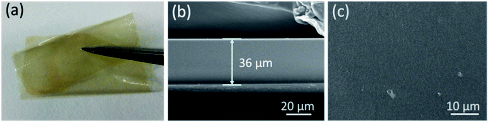 | ||
| Fig. 1 (a) Photo, SEM images (b) cross-section and (c) surface of CCPENS-0.6. | ||
IEC, WU and SR of the AEM
As a critical factor affecting the membrane properties, IEC represents the concentration of exchangeable ion groups in membrane matrix. As listed in Table 2, the theoretical IEC values between 1.75–1.92 meq. g−1 were calculated by the assumption that all benzyl bromide groups are quantitatively grafted with DIm groups and the bromide ions are totally exchanged with hydroxide ions. The experimental IEC values of CCPENS-x AEMs in the range of 1.56–1.65 meq. g−1 were measured by titration method and slightly lower than the corresponding theoretical IEC value. This is probably due to the high steric hindrance effect of long alkylene chain in DIm and the cardo groups in the main chains, which lead to incomplete quaternization reactions.| AEMs | IEC (meq. g−1) | λc | Tensile strength (MPa) | Elongation at break (%) | Td-5% (°C) | |||
|---|---|---|---|---|---|---|---|---|
| Theo.a | Exp.b | 30 °C | 60 °C | 80 °C | ||||
| a Calculated from the polymer composition and the bromination degree of BCPENS-x.b Estimated by back titration.c Calculated from the WU and the Exp. IEC of the AEMs. | ||||||||
| CCPENS-0.2 | 1.75 | 1.56 | 8.61 | 10.49 | 12.74 | 24.2 ± 0.4 | 4.8 ± 0.2 | 196.0 |
| CCPENS-0.4 | 1.80 | 1.58 | 8.18 | 9.94 | 11.41 | 24.8 ± 0.5 | 5.5 ± 0.3 | 206.6 |
| CCPENS-0.6 | 1.84 | 1.61 | 8.13 | 9.58 | 10.1 | 26.5 ± 0.5 | 7.3 ± 0.4 | 220.4 |
| CCPENS-0.8 | 1.92 | 1.65 | 7.37 | 8.61 | 9.11 | 27.6 ± 0.6 | 6.1 ± 0.4 | 232.2 |
AEM with a suitable level of WU and SR is essential for both a valuable ionic conductivity and an acceptable mechanical strength. As shown in Fig. 2, the WU decreased slightly from 24.2% to 21.9% at 30 °C and 35.8% to 27.1% at 80 °C from CCPENS-0.2 to CCPENS-0.8, and the corresponding SR decreased from 7.8% to 6.8% at 30 °C and from 12.7% to 9.2% at 80 °C. For a better comparison of the WU in the CCPENS-x membranes, we also calculated the hydration numbers (λ). As shown in Table 2, λ for CCPENS-x is between 7.37–8.61 at 30 °C and 9.11–12.74 at 80 °C. In summary, both the WU, SR and λ of the CCPENS-x tend to decrease with increasing the nitrile group content. It is considered that the nitrile groups with strong polarity could strengthen the intra/interchain interaction and thus restrict the water absorption and membrane swelling.46,49
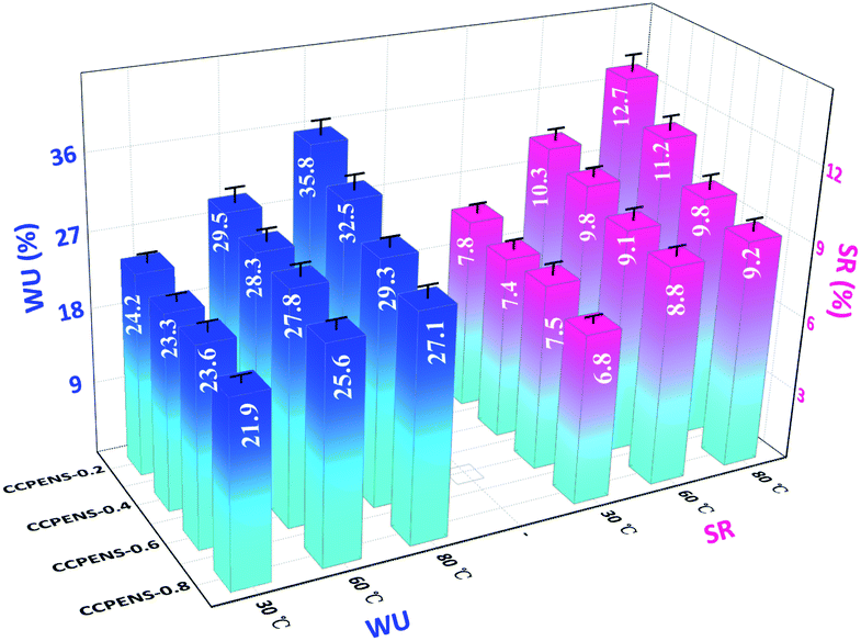 | ||
| Fig. 2 WU and SR of CCPENS-x AEMs at different temperatures. | ||
A comparison of the swelling ratio of CCPENS-x membranes with some random-type AEMs,16,18 block-type AEMs,27,29,31 side-chain-type AEMs32,34,35 and comb-shaped AEMs38–40 is shown in Fig. 3, as a function of IEC at 80 °C. The CCPENS-x membranes displayed a lower swelling ratio at a moderate level of IEC, which reveals that the AEMs have good dimensional stabilities and anti-swelling properties. Besides the nitrile groups, the membrane structure of the comb-shaped side chains and cardo-based main chains also plays an important role. The long carbon chains of the DIm groups together with the bulky cardo groups can provide an integrated steric hindrance effect and fence off each chain to construct some inter-chain spacing, in which the water molecules could be placed and trapped.50,51
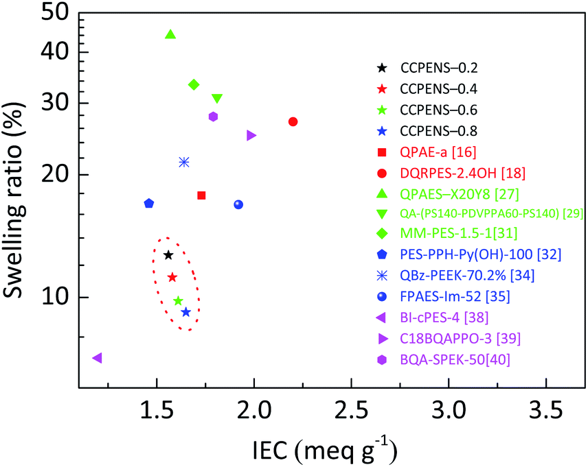 | ||
| Fig. 3 Swelling ratio of the AEMs as a function of IEC at 80 °C. | ||
Ionic conductivity (σ), apparent activation energy (Ea) and membrane morphology
As a critical property of AEMs, the ionic conductivity of CCPENS-x membranes was investigated as a function of temperature. As shown in Fig. 4a, the conductivity increases along with the raising temperature due to the promoted water mobility. Moreover, with the nitrile group content increased from CCPENS-0.2 to CCPENS-0.8, the conductivity improves from 25.8 to 39.5 mS cm−1 at 30 °C and from 58.6 to 83 mS cm−1 at 80 °C. To investigate the ionic conduction behavior more deeply, we displayed the ionic conductivity data as the Arrhenius plot and found it is almost linear. Then the apparent activation energy (Ea) was calculated by Ea = −R × b, where R represents the gas constant (8.314 J mol−1 K−1) and b refers to the slope of the ln![[thin space (1/6-em)]](https://www.rsc.org/images/entities/char_2009.gif) σ vs. 1000/T curves.18 As shown in Fig. 4b, the Ea of CCPENS-x membrane was estimated and decreased from 15.43 to 12.74 kJ mol−1 by increasing the nitrile group content. Furthermore, the Ea values of CCPENS-x are much lower than that of the reported comb-shaped membranes.38,40
σ vs. 1000/T curves.18 As shown in Fig. 4b, the Ea of CCPENS-x membrane was estimated and decreased from 15.43 to 12.74 kJ mol−1 by increasing the nitrile group content. Furthermore, the Ea values of CCPENS-x are much lower than that of the reported comb-shaped membranes.38,40
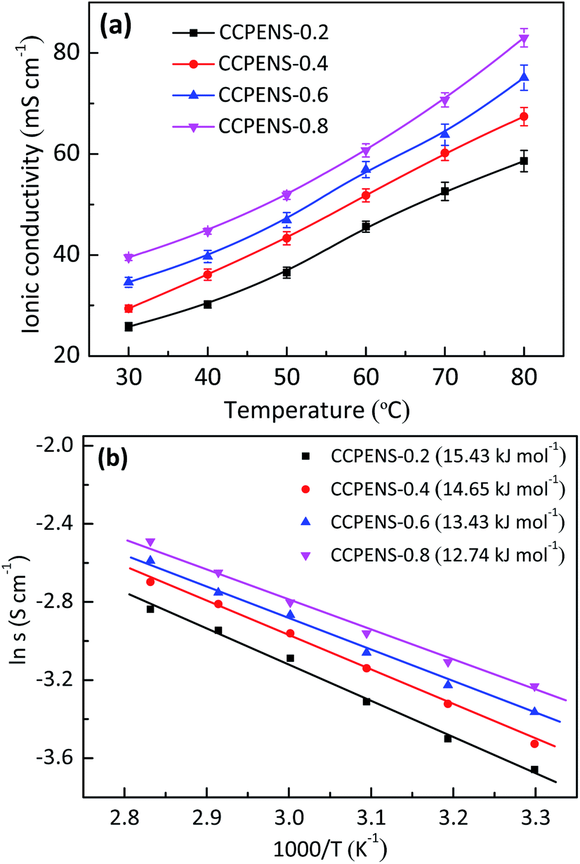 | ||
| Fig. 4 (a) Temperature dependence of ionic conductivity and (b) Arrhenius plots of CCPENS-x AEMs. | ||
The close relationship between ionic conduction behavior and nitrile group content would be attributed to the difference in membrane morphology. As shown in Fig. 5a and b of the AFM images, the darker and cluster-like regions are ascribed to the soft hydrophilic ionic domains, and the brighter regions are ascribed to the hard hydrophobic polymer chains.37 It could be observed that both CCPENS-0.2 and CCPENS-0.8 exhibited clear hydrophilic/hydrophobic microphase-separated morphologies. Besides, CCPENS-0.8 exhibited more distinct phase-separated morphology and formed larger and more interconnected ionic domains than CCPENS-0.2. The clear microphase separation of CCPENS-x can be attributed to the well-designed architecture of cardo-based main chains and comb-shaped C10 long alkyl side chains bearing imidazolium groups.37,41 Moreover, with the nitrile group content increased, the intra/intermolecular interaction is obviously enhanced and the polymer main chains are more strongly aligned (Scheme 2). As a result, defined spaces could be formed between the chains for ion transportation, where the imidazolium functional groups can be assemble and concentrated to form larger and more interconnected ionic domains, resulting in more efficient ion transport channels and lower Ea values together with higher conductivities.
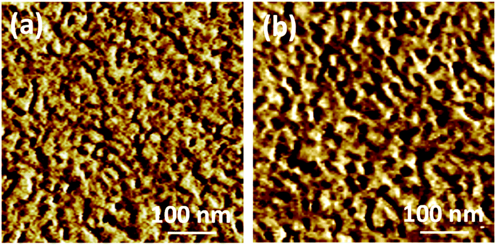 | ||
| Fig. 5 AFM phase images of (a) CCPENS-0.2 and (b) CCPENS-0.8 membranes. | ||
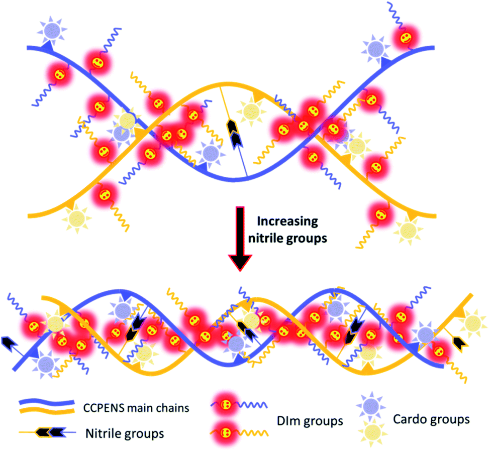 | ||
| Scheme 2 Schematic process of morphological changes for CCPENS-x. | ||
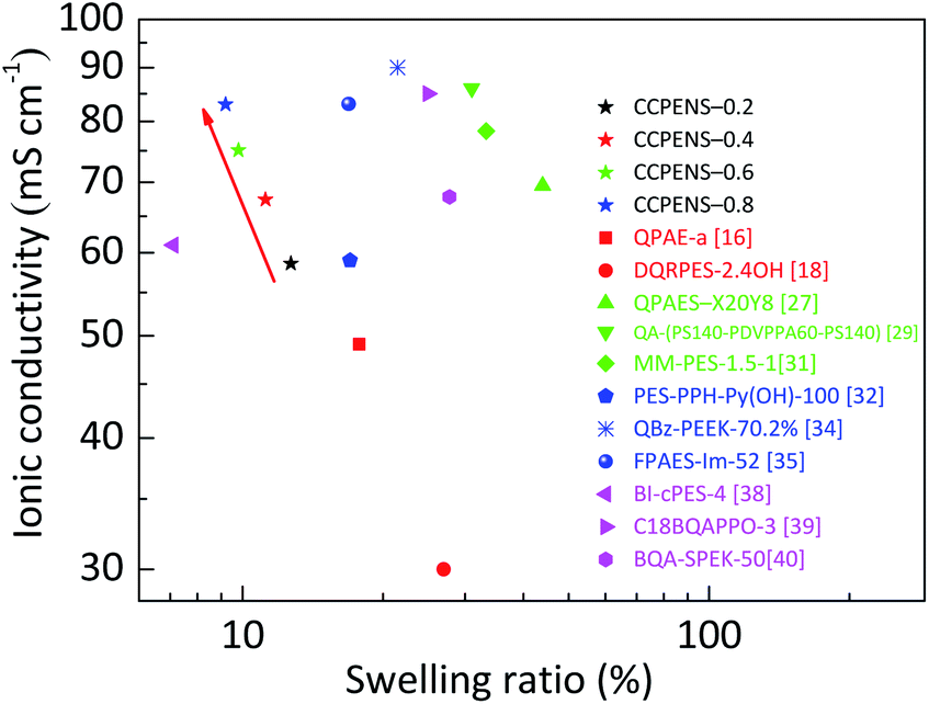
Furthermore, CCPENS-x membranes are found to have superb ratios of conductivity to swelling ratio at 80 °C. Fig. 6 shows the comparison of swelling ratio and ionic conductivity of CCPENS-x with some recently reported AEMs at 80 °C. On the top-left portion of the graph, CCPENS-x with more nitrile groups showed lower swelling ratio and higher conductivity. This suggests that it is an effective method to improve conductivity and restrain dimensional swelling by regulating the content of nitrile groups in CCPENS-x AEMs in this work.
 | ||
| Fig. 6 Ionic conductivity of the AEMs as a function of swelling ratio at 80 °C. | ||
Mechanical property and thermal stability
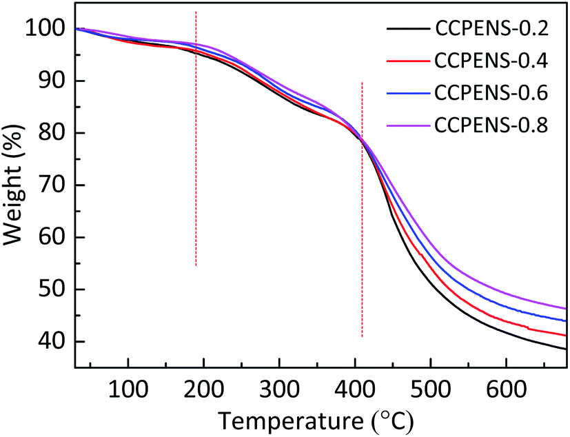
Desirable mechanical properties of the AEMs are required for their practical applications. Table 2 presents the mechanical properties of CCPENS-x. Benefitted from the low levels of swelling ratio, CCPENS-x membranes under the hydrated condition exhibited good tensile strength and elongation at break in the range of 24.2–27.6 MPa and 4.8–7.3%, respectively. With nitrile group content increased from CCPENS-0.2 to CCPENS-0.6, the CCPENS-x showed a slight improvement for both tensile strength and elongation. It is reasonable considering that the membranes displayed lower water uptake and swelling ratio from CCPENS-0.2 to CCPENS-0.6 (Fig. 2). Water molecule could act as a plasticizer and weaken the mechanical properties of the AEMs.52Thermogravimetric analysis (TGA) was conducted under N2 to evaluate the thermal stability of CCPENS-x AEMs. As shown in Fig. 7, CCPENS-x all experienced three degradation stages: (1) the 1st small weight loss between 30 and 190 °C was related to the evaporation of residual absorbed water and bound water. (2) the 2nd step from 190 to 410 °C was attributed to the cleavage of C–N bond and decomposition of DIm groups. (3) the 3rd step above 410 °C was owing to the degradation of polymer main chains. In general, all of CCPENS-x membranes showed good thermal stability below 190 °C. Furthermore, the 5% weight decomposition temperatures (Td-5%) of CCPENS-x were increased with increasing the nitrile content (Table 2), which might be ascribed to the enhanced intra/intermolecular interaction and indicates the nitrile groups could improve the thermal stability of the AEMs.53
 | ||
| Fig. 7 TGA curves of CCPENS-x AEMs. | ||
Alkaline stability
We assessed the alkaline stability of as-prepared AEMs by monitoring the changes in ionic conductivity and IEC of CCPENS-0.8, which were immersed in a 1 M KOH solution at 80 °C. As shown in Fig. 8, after alkaline treatment of 480 h, CCPENS-0.8 membrane can maintain ∼75% (29.6 mS cm−1) of the initial conductivity. Meanwhile, the IEC correspondingly decreased from 1.65 to 1.13 meq. g−1. These could be due to the decomposition of imidazolium functional groups under alkaline environments.54,55 Fortunately, there are still some means to further improve the alkaline stability of as-prepared AEMs. For example, AEMs prepared by using quinuclidinium or piperidinium cations have been reported for superior alkaline stability.56,57 These researches inspire us to further enhance the alkaline stability of CCPENS-x membranes. | ||
| Fig. 8 Alkaline stability of CCPENS-0.8 in a 1 M KOH solution at 80 °C. | ||
Comparison of the present membranes with literature data
A comparison of membrane property between CCPENS-x and the AEMs reported in recent years is presented in Table S1 (ESI).† As observed, performance of the CCPENS-x AEMs is in good agreement with other researcher and shows good advantages in anti-swelling.Conclusions
A series of comb-shaped cardo poly(arylene ether nitrile sulfone) (CCPENS-x) AEMs bearing imidazolium groups on C10 long alkyl side chains was prepared by varying the content of nitrile groups. The IEC of the AEMs ranged from 1.56 to 1.65 meq. g−1. The content of nitrile groups has a significant impact on the morphology and properties of CCPENS-x AEMs. With the nitrile group content increased, the WU decreased from 24.2% to 21.9% at 30 °C and 35.8% to 27.1% at 80 °C, and the corresponding SR decreased from 7.8% to 6.8% at 30 °C and from 12.7% to 9.2% at 80 °C. Furthermore, CCPENS-x revealed larger and more interconnected ionic domains to form more efficient ion-transport channels from CCPENS-0.2 to CCPENS-0.8, and the corresponding ionic conductivity increased from 25.8 to 39.5 mS cm−1 at 30 °C and 58.6 to 83 mS cm−1 at 80 °C. Moreover, CCPENS-x with higher content of nitrile groups also exhibited better mechanical properties and thermal stability, and higher ratios of conductivity to swelling ratio at 80 °C. Further work will focus on the optimization of membrane alkaline stability.Conflicts of interest
There are no conflicts to declare.Acknowledgements
The authors gratefully acknowledge the National Natural Science Foundation of China [No. 21706032], the Young and Middle-aged Teachers Education Scientific Research Project of Fujian Province of China [No. JAT170378], and the Scientific Research Foundation of Huaqiao University (No. 605-50Y18020) for financial support.Notes and references
- Z. F. Pan, L. An, T. S. Zhao and Z. K. Tang, Prog. Energy Combust. Sci., 2018, 66, 141–175 CrossRef.
- Y. Chang, Y. Qin, Y. Yin, J. Zhang and X. Li, Appl. Energy, 2018, 230, 643–662 CrossRef CAS.
- G. Merle, M. Wessling and K. Nijmeijer, J. Membr. Sci., 2011, 377, 1–35 CrossRef CAS.
- J. Chen, C. Li, J. Wang, L. Li and Z. Wei, J. Mater. Chem. A, 2017, 5, 6318–6327 RSC.
- W. Huang, H. Zhong, D. Li, P. Tang and Y. Feng, Electrochim. Acta, 2015, 173, 575–580 CrossRef CAS.
- W. Sheng, A. P. Bivens, M. Myint, Z. Zhuang, R. V. Forest, Q. Fang, J. G. Chen and Y. Yan, Energy Environ. Sci., 2014, 7, 1719–1724 RSC.
- P. Moni, M. G. Pollachini, M. Wilhelm, J. Lorenz, C. Harms, M. M. Murshed and K. Rezwan, ACS Appl. Energy Mater., 2019, 2, 6078–6086 CrossRef CAS.
- S. Gottesfeld, D. R. Dekel, M. Page, C. Bae, Y. Yan, P. Zelenay and Y. S. Kim, J. Power Sources, 2018, 375, 170–184 CrossRef CAS.
- J. R. Varcoe, P. Atanassov, D. R. Dekel, A. M. Herring, M. A. Hickner, P. A. Kohl, A. R. Kucernak, W. E. Mustain, K. Nijmeijer, K. Scott, T. Xu and L. Zhuang, Energy Environ. Sci., 2014, 7, 3135–3191 RSC.
- M. A. Shehzad, X. Liang, A. Yasmin, X. Ge, X. Xiao, Y. Zhu, Z. Ge, Y. Wang, L. Wu and T. Xu, J. Mater. Chem. A, 2019, 7, 10030–10040 RSC.
- X. Chu, Y. Shi, L. Liu, Y. Huang and N. Li, J. Mater. Chem. A, 2019, 7, 7717–7727 RSC.
- L. Wang and M. A. Hickner, Soft Matter, 2016, 12, 5359–5371 RSC.
- J. R. Nykaza, Y. Ye, R. L. Nelson, A. C. Jackson, F. L. Beyer, E. M. Davis, K. Page, S. Sharick, K. I. Winey and Y. A. Elabd, Soft Matter, 2016, 12, 1133–1144 RSC.
- B. H. Oh, A. R. Kim and D. J. Yoo, Int. J. Hydrogen Energy, 2019, 44, 4281–4292 CrossRef CAS.
- M. Zhang, C. Shan, L. Liu, J. Liao, Q. Chen, M. Zhu, Y. Wang, L. An and N. Li, ACS Appl. Mater. Interfaces, 2016, 8, 23321–23330 CrossRef CAS PubMed.
- X. Li, Q. Liu, Y. Yu and Y. Meng, J. Mater. Chem. A, 2013, 1, 4324–4335 RSC.
- K. H. Lee, D. H. Cho, Y. M. Kim, S. J. Moon, J. G. Seong, D. W. Shin, J. Y. Sohn, J. F. Kim and Y. M. Lee, Energy Environ. Sci., 2017, 10, 275–285 RSC.
- X. Dong, D. Lv, J. Zheng, B. Xue, W. Bi, S. Li and S. Zhang, J. Membr. Sci., 2017, 535, 301–311 CrossRef CAS.
- K. Yoshimura, Y. Zhao, A. Hiroki, Y. Kishiyama, H. Shishitani, S. Yamaguchi, H. Tanaka, S. Koizumi, J. E. Houston, A. Radulescu, M. S. Appavou, D. Richterf and Y. Maekawa, Soft Matter, 2018, 14, 9118–9131 RSC.
- B. Xue, Q. Wang, J. Zheng, S. Li and S. Zhang, J. Membr. Sci., 2020, 601, 117923 CrossRef.
- S. Kim, S. Yang and D. Kim, Int. J. Hydrogen Energy, 2017, 42, 12496–12506 CrossRef CAS.
- C. G. Morandi, R. Peach, H. M. Krieg and J. Kerres, J. Mater. Chem. A, 2015, 3, 1110–1120 RSC.
- R. Ren, S. Zhang, H. A. Miller, F. Vizza, J. R. Varcoe and Q. He, ACS Appl. Energy Mater., 2019, 2, 4576–4581 CrossRef CAS.
- D. Yao, T. Wei, L. Shang, H. Na and C. Zhao, RSC Adv., 2019, 9, 7975–7983 RSC.
- P. Papakonstantinou and V. Deimede, RSC Adv., 2016, 6, 114329–114343 RSC.
- M. T. Kwasny and G. N. Tew, J. Mater. Chem. A, 2017, 5, 1400–1405 RSC.
- X. Li, Q. Liu, Y. Yu and Y. Meng, J. Membr. Sci., 2014, 467, 1–12 CrossRef CAS.
- D. Shin, A. F. Nugraha, F. Wijaya, S. Lee, E. Kim, J. Choi, H. J. Kim and B. Bae, RSC Adv., 2019, 9, 21106–21115 RSC.
- M. Zhu, M. Zhang, Q. Chen, Y. Su, Z. Zhang, L. Liu, Y. Wang, L. An and N. Li, Polym. Chem., 2017, 8, 2074–2086 RSC.
- X. Zhang, S. Li, P. Chen, J. Fang, Q. Shi, Q. Weng, X. Luo, X. Chen and Z. An, Int. J. Hydrogen Energy, 2018, 43, 3716–3730 CrossRef CAS.
- S. Kwon, A. H. N. Rao and T. H Kim, J. Power Sources, 2018, 375, 421–432 CrossRef CAS.
- F. Gong, R. Wang, X. Chen, P. Chen, Z. An and S. Zhang, Polym. Chem., 2017, 8, 4207–4219 RSC.
- Y. Zhu, L. Ding, X. Liang, M. A. Shehzad, L. Wang, X. Ge, Y. He, L. Wu, J. R. Varcoe and T. Xu, Energy Environ. Sci., 2018, 11, 3472–3479 RSC.
- Z. Zhang, X. Xiao, X. Yan, X. Liang and L. Wu, J. Membr. Sci., 2019, 574, 205–211 CrossRef CAS.
- B. Shen and H. Pu, Int. J. Hydrogen Energy, 2019, 44, 11057–11065 CrossRef CAS.
- D. Koronka, A. Matsumoto, K. Otsuji and K. Miyatake, RSC Adv., 2019, 9, 37391–37402 RSC.
- L. Liu, X. Chu, J. Liao, Y. Huang, Y. Li, Z. Ge, M. A. Hickner and N. Li, Energy Environ. Sci., 2018, 11, 435–446 RSC.
- A. H. N. Rao, S. Y. Nam and T. H. Kim, RSC Adv., 2016, 6, 16168–16176 RSC.
- Y. He, J. Si, L. Wu, S. Chen, Y. Zhu, J. Pan, X. Ge, Z. Yang and T. Xu, J. Membr. Sci., 2016, 515, 189–195 CrossRef CAS.
- X. L. Gao, Q. Yang, H. Y. Wu, Q. H. Sun, Z. Y. Zhu, Q. G. Zhang, A. M. Zhu and Q. L. Liu, J. Membr. Sci., 2019, 589, 117247 CrossRef CAS.
- L. Zeng and T. S. Zhao, J. Power Sources, 2016, 303, 354–362 CrossRef CAS.
- J. Pan, C. Chen, Y. Li, L. Wang, L. Tan, G. Li, X. Tang, L. Xiao, J. Lu and L. Zhuang, Energy Environ. Sci., 2014, 7, 354–360 RSC.
- Y. Hu, B. Wang, X. Li, D. Chen and W. Zhang, J. Power Sources, 2018, 387, 33–42 CrossRef CAS.
- G. Shukla and V. K. Shahi, ACS Appl. Energy Mater., 2018, 1, 1175–1182 CrossRef CAS.
- A. N. Lai, L. S. Wang, C. X. Lin, Y. Z. Zhuo, Q. G. Zhang, A. M. Zhu and Q. L. Liu, ACS Appl. Mater. Interfaces, 2015, 7, 8284–8292 CrossRef CAS PubMed.
- D. S. Kim, Y. S. Kim, M. D. Guiver and B. S. Pivovar, J. Membr. Sci., 2008, 321, 199–208 CrossRef CAS.
- Y. Huang, J. Liu, P. Zheng, M. Feng, J. Chen and X. Liu, J. Polym. Res., 2016, 23, 256 CrossRef.
- M. Feng, T. Cheng, X. Huang, Y. Huang and X. Liu, RSC Adv., 2017, 7, 2971–2978 RSC.
- Y. S. Kim, D. S. Kim, B. Liu, M. D. Guiver and B. S. Pivovar, J. Electrochem. Soc., 2008, 155, B21–B26 CrossRef CAS.
- X. Dong, S. Hou, H. Mao, J. Zheng and S. Zhang, J. Membr. Sci., 2016, 518, 31–39 CrossRef CAS.
- J. Zheng, J. Wang, S. Zhang, T. Yuan and H. Yang, J. Power Sources, 2014, 245, 1005–1013 CrossRef CAS.
- H. N. Dhakal, Z. Y. Zhang and M. O. W. Richardson, Compos. Sci. Technol., 2007, 67, 1674–1683 CrossRef CAS.
- M. Guo, B. Liu, S. Guan, L. Li, C. Liu, Y. Zhang and Z. Jiang, J. Power Sources, 2010, 195, 4613–4621 CrossRef CAS.
- J. Cheng, G. He and F. Zhang, Int. J. Hydrogen Energy, 2015, 40, 7348–7360 CrossRef CAS.
- H. Wei, Y. Li, S. Wang, G. Tao, T. Wang, S. Cheng, S. Yang and Y. Ding, J. Membr. Sci., 2019, 579, 219–229 CrossRef CAS.
- A. Allushi, T. H. Pham, J. S. Olsson and P. Jannasch, J. Mater. Chem. A, 2019, 7, 27164–27174 RSC.
- J. S. Olsson, T. H. Pham and P. Jannasch, Adv. Funct. Mater., 2018, 28, 1702758 CrossRef.
Footnote |
| † Electronic supplementary information (ESI) available. See DOI: 10.1039/d0ra01798a |
| This journal is © The Royal Society of Chemistry 2020 |