
 Open Access Article
 This Open Access Article is licensed under a Creative Commons Attribution-Non Commercial 3.0 Unported Licence
TiO2-decorated porous carbon nanofiber interlayer for Li–S batteries
Meltem Yanilmaz
Department of Textile Engineering, Istanbul Technical University, Istanbul, Turkey. E-mail: yanilmaz@itu.edu.tr
First published on 28th April 2020
Abstract
Lithium–sulfur (Li–S) batteries are the most promising energy storage systems owing to their high energy density. However, shuttling of polysulfides detracts the electrochemical performance of Li–S batteries and thus prevents the commercialization of Li–S batteries. Here, TiO2@porous carbon nanofibers (TiO2@PCNFs) are fabricated via combining electrospinning and electrospraying techniques and the resultant TiO2@PCNFs are evaluated for use as an interlayer in Li–S batteries. TiO2 nanoparticles on PCNFs are observed from SEM and TEM images. A high initial discharge capacity of 1510 mA h g−1 is achieved owing to the novel approach of electrospinning the carbon precursor and electrospraying TiO2 nanoparticles simultaneously. In this approach TiO2 nanoparticles capture polysulfides with strong interaction and the PCNFs with high conductivity recycle and re-use the adsorbed polysulfides, thus leading to high reversible capacity and stable cycling performance. A high reversible capacity of 967 mA h g−1 is reached after 200 cycles at 0.2C. The cell with the TiO2@PCNF interlayer also delivers a reversible capacity of around 1100 mA h g−1 at 1C, while the cell without the interlayer exhibits a lower capacity of 400 mA h g−1. Therefore, this work presents a novel approach for designing interlayer materials with exceptional electrochemical performance for high performance Li–S batteries.
1. Introduction
Energy storage and conversion devices will play a critical role in the future as the fossil energy sources are diminishing.1,2 Lithium ion batteries have been widely used in many portable electronics and electric vehicles however safety is still an issue for lithium ion batteries.3,4 Lithium–sulfur batteries are attracting great interest due to ever-increasing demand for high capacity batteries. Sulfur has a high theoretical capacity of 1675 mA h g−1 with an operating voltage of 2.1 V. Furthermore, it is an environmentally friendly and naturally abundant material. However, the inherent poor conductivity, large volume chance of sulfur and shuttle effect deteriorate the electrochemical performance and prevent commercialization of Li–S batteries.4–9Several attempts have been reported including hollow TiO2-webbed carbon nanotubes,10 MXene nanosheets decorated with TiO2 quantum dots,11 hollow porous titanium nitride tubes,12 CoS @rGO,13 CNT/graphene–Li2S aerogel14 to improve electrochemical performance of Li–S batteries. However, introducing carbon in sulfur cathode leads to lower energy density and the complicated and high-cost methods are not suitable for scaling up.5,15 An atomic-scale electrocatalyst was reported to expedite the sulfur redox reactions in Li–S batteries by Li et al.8 and significant improvement in electrochemical performance was achieved. Lei et al.16 coated a thin layer of reduced graphene oxide/sodium lignosulfonate composite on the standard polypropylene separator and a highly robust battery with a capacity retention of 74% over 1000 cycles was reported. In another study, polyacrylonitrile and ammonium polyphosphate were electrospun into a multifunctional separator for stable and safe Li–S batteries.17 Chen et al.18 reported atomic interlamellar ion path lithiummontmorillonite for high sulfur content Li–S battery and high rate stable cycling performance was observed. Polyisoprene@sulfur in interlayers of Ti3C2Tx was reported as a novel structure to regulate the nucleation and heterogeneous growth of Li2S to prevent arbitrary Li2S accumulation on host surface.19
Inserting porous and conductive carbon interlayer between the cathode and separator has been reported to improve the conductivity of cathode and trap lithium polysulfides. Up to day, carbonized cellulose paper,20 carbon paper,21 carbonized filter paper,22 microporous carbon paper,23 carbon fiber cloth24 were reported, however, the improvement is not satisfactory due to low interaction between carbon and polysulfides. Thicker carbon layer is certainly more effective to physically absorb polysulfides however, it slows down ion movement and lowers volumetric energy density of the cells.15,25
It has been reported that metal oxides (TiO2, MnO2, and MgO, V2O5 etc.) and sulfides (MoS2, TiS2, VS2, etc.) have strong adsorption for the polysulfides, because of the intense electrostatic attraction between metal–oxygen bond and polysulfides. TiO2 also has the low cost advantage.5,6,15,26 In this work, electrospinning and electrospraying techniques were utilized simultaneously, for the first time, to fabricate interlayer materials for Li–S batteries. PAN/PMMA blend solution was electrospun while TiO2 dispersion in methanol was electrosprayed at the same time. Then, TiO2@PCNFs were obtained after the heat treatment in which PAN turned into carbon and PMMA generated pores. The obtained fibrous mat was directly used as an interlayer between the separator and the cathode in Li–S cells. In TiO2@PCNF interlayer, PCNF layer promotes electron transfer and TiO2 plays a vital role in entrapment of polysulfides via strong chemical interaction. The high initial capacity of 1510 mA h g−1 and the reversible capacity of 967 mA h g−1 were observed after 200 cycles from the cell with TiO2@PCNF interlayer, whereas the cell prepared with PCNF interlayer delivered initial capacity of 1326 mA h g−1 and reversible capacity of 500 mA h g−1 after 200 cycles. The cell prepared without interlayer only delivered initial capacity of 967 mA h g−1 and reversible capacity of 206 mA h g−1. The cell resistance and C-rate performance was also improved with conductive nanostructured carbon layer decorated with TiO2. Therefore, this work demonstrate that employing TiO2 decorated PCNF interlayer via electrospinning and electrospraying could be very effective approach to fabricate high performance Li–S batteries.
2. Experimental
Polyacrylonitrile (PAN, Mw = 150![[thin space (1/6-em)]](https://www.rsc.org/images/entities/char_2009.gif) 000), polymethylmethacrylate (PMMA, Mw = 200000) and N,N-dimethyl formamide (DMF), sulfur (99%), methanol, 1,3-dioxolane, 1,2 dimethoxyethane, bis(trifluoromethane), sulfonamide lithium, lithium nitrite, N-methyl-2-pyrrolidone were supplied from Sigma Aldrich. Polyvinylidene fluoride (PVDF, Solef 5130) and TiO2 with D30 nm were supplied from Solvay and SSNanomaterials, respectively.
000), polymethylmethacrylate (PMMA, Mw = 200000) and N,N-dimethyl formamide (DMF), sulfur (99%), methanol, 1,3-dioxolane, 1,2 dimethoxyethane, bis(trifluoromethane), sulfonamide lithium, lithium nitrite, N-methyl-2-pyrrolidone were supplied from Sigma Aldrich. Polyvinylidene fluoride (PVDF, Solef 5130) and TiO2 with D30 nm were supplied from Solvay and SSNanomaterials, respectively.
12 wt% PAN/PMMA (7/3, w/w) blend solution was prepared in DMF and stirred for 24 hours at ambient temperature while TiO2 dispersion was prepared in methanol. The PAN/PMMA solution was then electrospun into nanofibers and TiO2 dispersion was electrosprayed simultaneously with the following process parameters: flow rate of 1 ml h−1, voltage of 20 kV, and tip-to-collector distance of 20 cm. To form TiO2@PCNFs, electrospun PAN/PMMA nanofibers decorated with TiO2 nanoparticles were stabilized in air at 280 °C for 2.5 h with a heating rate of 5 °C min−1 and were carbonized at 800 °C for 2 h in argon atmosphere with a heating rate of 2 °C min−1, during which PAN nanofibers were converted to carbon nanofibers and PMMA was decomposed to generate pores in the carbon matrix.
The morphology of PCNFs, TiO2@PCNFs was investigated by JEOL SEM-7100-EDX scanning electron microscope and JEOL TEM-1400-EDX transmission electron microscope. X-ray diffraction (XRD) patterns were examined by using a diffractometer (Japan) with Cu Ka radiation (λ = 0.154 nm) in a 2θ range from 10° to 70°.
The sulfur cathode was prepared by casting a slurry containing 70 wt% pure sulfur, 20 wt% carbon and 10 wt% PVDF binder in NMP on the aluminum foil using doctor-blade technique, followed by drying in an air oven at 60 °C for 12 h. It is punched out and precisely weighed. The electrodes with sulfur loadings between 1 mg were cut into discs of 12 mm in diameter. The electrolyte was kept constant as 40 μl per 1 mg sulfur.
The charge–discharge tests of Li–S cells were conducted by using CR 2032 coin cells. The cells were assembled in an argon filled glovebox using electrolyte consisting of 1.0 M LiTFSI in distilled DME:DOL (1:1, v/v), sulfur cathode, separator, Li foil anode with TiO2@PCNF and PCNF interlayer. For comparison, the Li–S cells without interlayer was also assembled. Furthermore, electrochemical impedance spectroscopy (EIS) was employed to examine the resistance of the prepared cells in the range of 100 kHz to 0.1 Hz with 5 mV amplitude and cycling voltammetry was performed to investigate the electrochemical characteristics.
3. Results and discussion
3.1 Morphology and structure characterization
SEM images of PCNFs and TiO2@PCNFs are shown in Fig. 1. The average nanofiber diameter was measured to be around 160 nm for PCNFs. SEM image of TiO2@PCNFs revealed that TiO2 nanoparticles were decorated on PCNFs. In order to further investigate the morphology of TiO2@PCNFs, TEM images are reported in Fig. 2. TEM images also proved uniform distribution of TiO2 nanoparticles on highly conductive carbon nanofiber interlayer which not only could buffer the volume expansion of sulfur cathode during lithiation but also provide pathway for fast transport of electrons during cycling process. Furthermore, TiO2 nanoparticles chemically adsorb polysulfides owing to strong interaction between TiO2 and polysulfides and hence leads to enhanced cycling performance with satisfactory reversible capacity.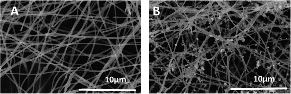 | ||
| Fig. 1 SEM images of PCNFs (A), TiO2@PCNFs (B). | ||
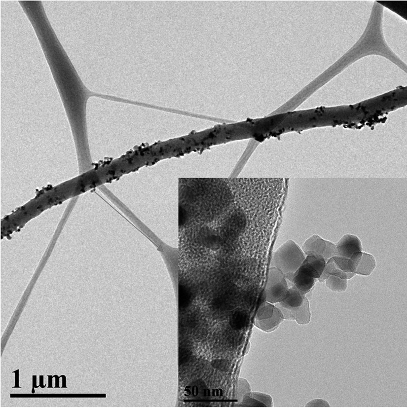 | ||
| Fig. 2 TEM images of TiO2@PCNFs. | ||
XRD diffraction patterns of PCNFs and TiO2@PCNFs are shown in Fig. 3. The peak at about 270 in the two curves demonstrated the existence of nongraphic carbon. The peak at 250 in the curve for TiO2@PCNFs was the typical and strongest peak of rutile TiO2 and all the identified peaks in the XRD pattern could be assigned to the rutile TiO2 phase.25 BET surface area measurement results of PCNFs and TiO2@PCNFs were also reported in Table 1. The surface areas were 1306 m2 g−1 and 1418 m2 g−1 respectively, for PCNFs and TiO2@PCNFs. The surface area of TiO2@PCNFs was slightly increased compared to PCNFs owing to new surface contributed by the TiO2 nanoparticle deposition.
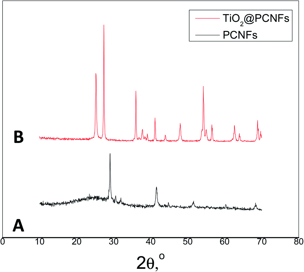 | ||
| Fig. 3 XRD patterns of PCNFs (A), TiO2@PCNFs (B). | ||
| Sample | Specific surface area, m2 g−1 |
|---|---|
| PCNFs | 1306 |
| TiO2@PCNFs | 1418 |
3.2 Electrochemical characteristics
Cycling voltammograms (CVs) of the Li–S cells with TiO2@PCNF interlayer, PCNF interlayer, and without interlayer are shown in Fig. 4. For all cells studied, in every cathodic scan, the peaks were observed at 2.3 V and 2 V, associated with the transformation of cyclo S to polysulfides (Li2Sx, 4 ≤ x ≤ 8) and reduction of polysulfides into Li2S2 and Li2S, respectively.5 Two anodic peaks were seen at around 2.3 V and 2.4 V where the insoluble LiS changed into polysulfides and then the element S. The CV of the Li–S cells with TiO2@PCNF interlayer showed the highest current, indicating higher reversible capacity compared to the cell with PCNF interlayer and without interlayer. Zhuang et al.6 prepared MoO2 containing CNF interlayer and higher current observed from the CV curves of the cell with MoO2/CNF interlayer compared to that of the cell without interlayer, indicating better sulfur utilization due to strong polysulfide adsorption capacity of MoO2/CNF interlayer.6 Moreover, after the first cycle, no obvious change was observed, indicating superior electrochemical performance.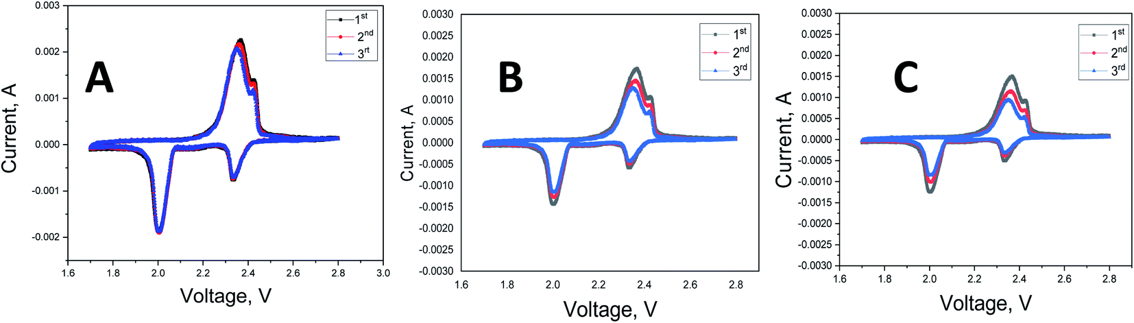 | ||
| Fig. 4 Cyclic voltammograms of Li–S cells with TiO2@PCNF interlayer (A), PCNF interlayer (B) and without interlayer (C). | ||
Fig. 5 shows the first cycle discharge–charge curves for the cells with TiO2@PCNF interlayer, PCNF interlayer, and without interlayer. The typical two-plateau behavior of Li–S battery was observed at around 2.3 and 2.1 V, which was consisted with the peaks in the CV curves. The cell without interlayer delivered an initial discharge capacity of 884 mA h g−1, meaning 52% utilization while the cells with TiO2@PCNF interlayer and PCNF interlayer reached the discharge capacities of 1510 and 1326 mA h g−1, corresponding to 90% and 79% utilization, respectively. The enhanced initial discharge capacity for the cells with TiO2@PCNF interlayer was attributed to conductive nanostructured carbon network decorated with TiO2 nanoparticles, in which PCNF provides excellent electron pathway while TiO2 nanoparticles provide strong chemical adsorption for polysulfides.
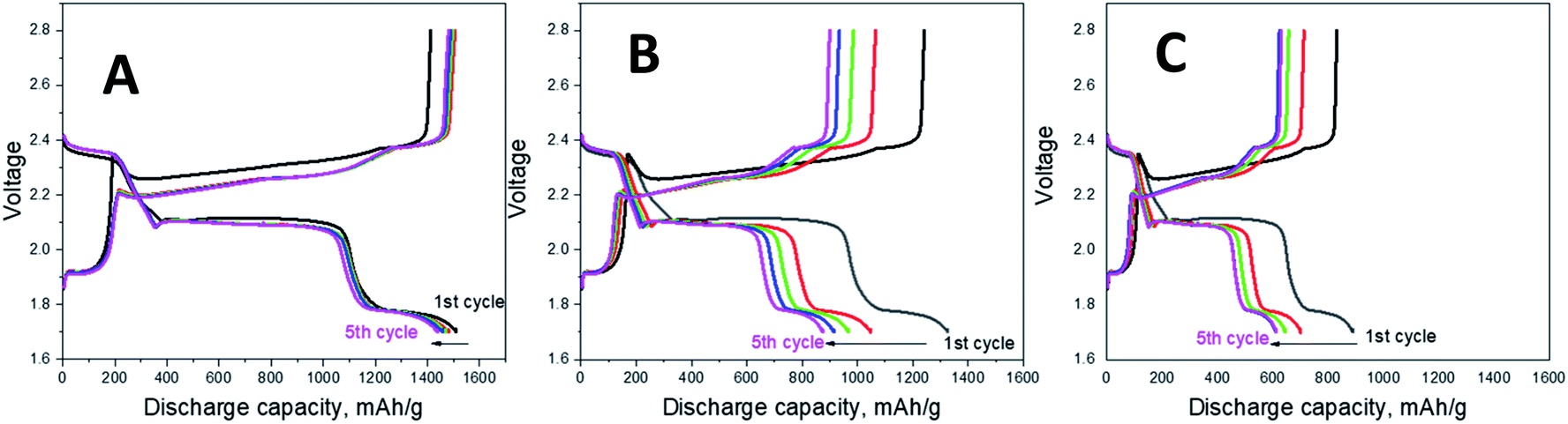 | ||
| Fig. 5 Galvanostatic charge/discharge profiles of Li–S cells with TiO2@PCNF interlayer (A), PCNF interlayer (B) and without interlayer (C). | ||
The rate performance was measured at a stepwise current stage from 0.2C to 0.5C, to 1C, to 2C, and then back to 0.2C. When current changes to 0.2C to 0.5C, to 1C, to 2C, the cell with TiO2@PCNF interlayer exhibited the discharge capacities of around 1400, 1200, 1150, and 900 mA h g−1 whereas the cell without interlayer delivered the capacities of 515, 375, 272 and 94 mA h g−1.
Superior C rate performance illustrates that TiO2@PCNF interlayer was effective for preventing shuttle of sulfur species. TiO2 nanoparticles decorated on PCNFs can capture polysulfides effectively via the strong chemical adsorption resulting from the intense electrostatic attraction between the Ti–O bond and the sulfur species. Xiao et al.5 introduced graphene/TiO2 interlayer and they also reported enhanced C rate performance owing to low resistance, highly efficient entrapment of polysulfides and accommodated volume variations by using graphene/TiO2 interlayer.5 Cycling performance at 1C was also reported in Fig. 6 and discharge capacity of above 700 mA h g−1 was achieved after 200 cycles which was significantly higher than that (around 400 mA h g−1) of Li–S cells without interlayer.17
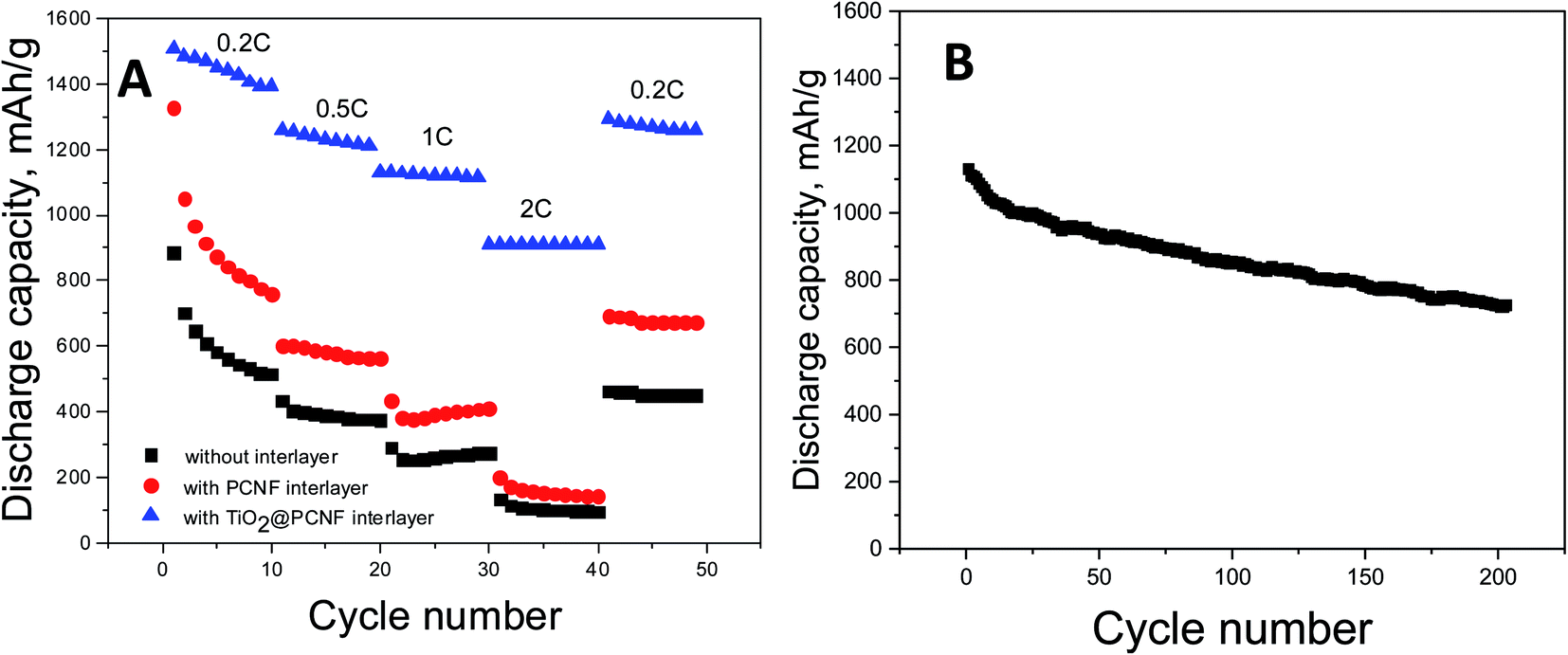 | ||
| Fig. 6 C-rate performance of Li–S cells with TiO2@PCNF interlayer, PCNF interlayer and without interlayer (A) cycling performance of Li–S cell with TiO2@PCNF interlayer at 1C (B). | ||
Fig. 7 shows the cycling stability for the cells with TiO2@PCNF interlayer, PCNF interlayer, and without interlayer. The cells with TiO2@PCNF interlayer not only delivered the highest reversible capacity but also showed the highest capacity retention. In 200 cycles, the cell with TiO2@PCNF interlayer delivered the high capacity of 968 mA h g−1 while the cells with PCNF interlayer and without interlayer only had the capacities of 498 and 206 mA h g−1, respectively. The remarkable improvement could be attributed to improved electrical conductivity with nanostructured carbon network and strong adsorption of polysulfides with TiO2 nanoparticles. Moreover carbon structure in the interlayer provided buffer like structure and reduced fracture in the cathode and provided conductive layer for re-using polysulfides. Jiao et al.7 reported TiO/Mxene interlayer and better cycling performance with higher capacity (900 mA h g−1 compared to 600 mA h g−1 in 200 cycles) was attributed to strong polysulfide capturing ability of TiO2.7
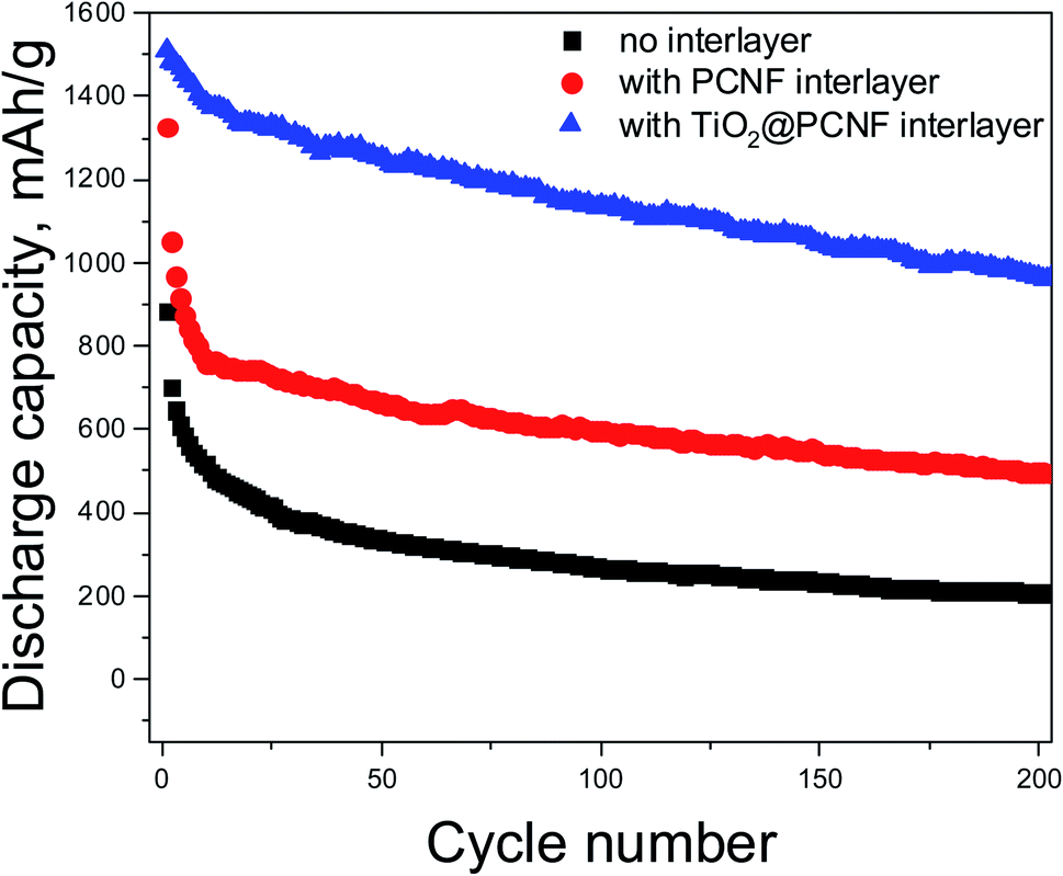 | ||
| Fig. 7 Galvanostatic charge–discharge curves of Li–S cells with TiO2@PCNF interlayer, PCNF interlayer and without interlayer. | ||
Electrochemical impedance spectroscopy of the cells before and after cycling is shown in Fig. 8. For all the cells studied, a semi-circle in the high to medium frequency region was observed, which is typical for Li–S cells. The semi-circle indicates the charge transfer resistance at the interface between the cathode and the electrolyte.15 The charge transfer resistance of the cell with TiO2@PCNF interlayer and PCNF interlayer was 25 and 50 ohm, respectively, whereas the cell without interlayer exhibited the charge transfer resistance of 55 ohm. The lower resistance of the cell with TiO2@PCNF interlayer was attributed to conductive porous carbon network, which provides excellent electron pathway and thus leads to higher sulfur utilization. After cycling the resistance values were 30, 60 and 80 ohm for the cells with TiO2@PCNF interlayer, PCNF interlayer, and without interlayer, respectively, indicating the formation of an insulating layer of solid Li2S2/Li2S between the separator and the cathode.25 After 200 cycles, the cell with TiO2@PCNF interlayer, showed the lowest resistance due to the sufficient infiltration of the electrolyte to the interlayer and the sulfur cathode, indicating that TiO2@PCNF interlayer restricted polysulfide shuttling, supported lithium ion movement and thus leading to lower resistance with superior cycling and C rate performance. All these results proves that TiO2@PCNF interlayer was effective in prohibiting the shuttle effect of polysulfides in Li–S batteries.
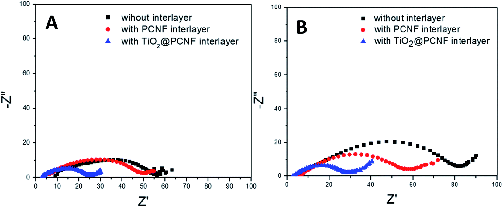 | ||
| Fig. 8 Electrochemical impedance spectra of the Li–S cells with TiO2@PCNF interlayer, PCNF interlayer and without interlayer before (A) and after (B) cycling. | ||
4. Conclusion
A facile and effective way to fabricate TiO2 decorated PCNF interlayer was developed for Li–S batteries. The enhanced cycling and C rate performance was achieved. The conductive PCNF network provided excellent electron pathway, and thus improved electron transfer and help reutilization of active material while TiO2 nanoparticles adsorbed polysulfides effectively through strong chemical adsorption. This study reported one step feasible approach to fabricate conductive interlayer with highly adsorbent nanoparticles and tunable properties to improve electrochemical performance of Li–S batteries without electrode modification. This novel porous and conductive structure not only adsorb polysulfides but also help reutilization of the active material on the cathode side. The findings in this work reveal a scalable and effective method to fabricate interlayers that could provide remarkable development for Li–S batteries.Conflicts of interest
The authors declare that they have no conflict of interest.References
- H. Xiang, J. Chen and Z. Li, et al., An inorganic membrane as a separator for lithium-ion battery, J. Power Sources, 2011, 196, 8651–8655 CrossRef CAS.
- X. Chen, W. He and L.-X. Ding, et al., Enhancing interfacial contact in all solid state batteries with a cathode-supported solid electrolyte membrane framework, Energy Environ. Sci., 2019, 12, 938–944 RSC.
- Z. Jiang, H. Xie and S. Wang, et al., Perovskite Membranes with Vertically Aligned Microchannels for All-Solid-State Lithium Batteries, Adv. Energy Mater., 2018, 8, 1801433 CrossRef.
- C. Ye, Y. Jiao and D. Chao, et al., Electron-State Confinement of Polysulfides for Highly Stable Sodium–Sulfur Batteries, Adv. Mater., 2020, 1907557 CrossRef CAS PubMed.
- Z. Xiao, Z. Yang and L. Wang, et al., A lightweight TiO2/graphene interlayer, applied as a highly effective polysulfide absorbent for fast, long-life lithium–sulfur batteries, Adv. Mater., 2015, 27, 2891–2898 CrossRef CAS PubMed.
- R. Zhuang, S. Yao and X. Shen, et al., A freestanding MoO2-decorated carbon nanofibers interlayer for rechargeable lithium sulfur battery, Int. J. Energy Res., 2019, 43, 1111–1120 CrossRef CAS.
- L. Jiao, C. Zhang and C. Geng, et al., Capture and Catalytic Conversion of Polysulfides by In Situ Built TiO2-MXene Heterostructures for Lithium–Sulfur Batteries, Adv. Energy Mater., 2019, 9, 1900219 CrossRef.
- B. Q. Li, L. Kong and C. X. Zhao, et al., Expediting redox kinetics of sulfur species by atomic-scale electrocatalysts in lithium–sulfur batteries, Infomatics, 2019, 1, 533–541 CrossRef.
- W. Chen, Y. Hu and W. Lv, et al., Lithiophilic montmorillonite serves as lithium ion reservoir to facilitate uniform lithium deposition, Nat. Commun., 2019, 10, 1–9 CrossRef PubMed.
- J. Y. Hwang, H. M. Kim and S. K. Lee, et al., High-Energy, High-Rate, Lithium–Sulfur Batteries: Synergetic Effect of Hollow TiO2-Webbed Carbon Nanotubes and a Dual Functional Carbon-Paper Interlayer, Adv. Energy Mater., 2016, 6, 1501480 CrossRef.
- X. T. Gao, Y. Xie and X. D. Zhu, et al., Ultrathin MXene nanosheets decorated with TiO2 quantum dots as an efficient sulfur host toward fast and stable Li–S batteries, Small, 2018, 14, 1802443 CrossRef PubMed.
- D.-R. Deng, T.-H. An and Y.-J. Li, et al., Hollow porous titanium nitride tubes as a cathode electrode for extremely stable Li–S batteries, J. Mater. Chem. A, 2016, 4, 16184–16190 RSC.
- C. Gao, C. Fang and H. Zhao, et al., Rational design of multi-functional CoS@ rGO composite for performance enhanced Li-S cathode, J. Power Sources, 2019, 421, 132–138 CrossRef CAS.
- J. He, Y. Chen and W. Lv, et al., Three-dimensional CNT/graphene–Li2S aerogel as freestanding cathode for high-performance Li–S batteries, ACS Energy Lett., 2016, 1, 820–826 CrossRef CAS.
- Y. Liu, X. Qin and S. Zhang, et al., Fe3O4-Decorated Porous Graphene Interlayer for High-Performance Lithium–Sulfur Batteries, ACS Appl. Mater. Interfaces, 2018, 10, 26264–26273 CrossRef CAS PubMed.
- T. Lei, W. Chen and W. Lv, et al., Inhibiting polysulfide shuttling with a graphene composite separator for highly robust lithium-sulfur batteries, Joule, 2018, 2, 2091–2104 CrossRef CAS.
- T. Lei, W. Chen and Y. Hu, et al., A Nonflammable and Thermotolerant Separator Suppresses Polysulfide Dissolution for Safe and Long-Cycle Lithium-Sulfur Batteries, Adv. Energy Mater., 2018, 8, 1802441 CrossRef.
- W. Chen, T. Lei and W. Lv, et al., Atomic interlamellar ion path in high sulfur content lithium-montmorillonite host enables high-rate and stable lithium–sulfur battery, Adv. Mater., 2018, 30, 1804084 CrossRef PubMed.
- T. Lei, Y. Hu and W. Chen, et al., Genetic engineering of porous sulfur species with molecular target prevents host passivation in lithium sulfur batteries, Energy Storage Materials, 2020, 26, 65–72 CrossRef.
- S. Li, G. Ren and M. N. F. Hoque, et al., Carbonized cellulose paper as an effective interlayer in lithium-sulfur batteries, Appl. Surf. Sci., 2017, 396, 637–643 CrossRef CAS.
- C. Zu, Y.-S. Su and Y. Fu, et al., Improved lithium–sulfur cells with a treated carbon paper interlayer, Phys. Chem. Chem. Phys., 2013, 15, 2291–2297 RSC.
- K. Zhang, Q. Li and L. Zhang, et al., From filter paper to carbon paper and toward Li–S battery interlayer, Mater. Lett., 2014, 121, 198–201 CrossRef CAS.
- Y.-S. Su and A. Manthiram, Lithium–sulphur batteries with a microporous carbon paper as a bifunctional interlayer, Nat. Commun., 2012, 3, 1–6 CrossRef.
- Y. Yang, W. Sun and J. Zhang, et al., High rate and stable cycling of lithium-sulfur batteries with carbon fiber cloth interlayer, Electrochim. Acta, 2016, 209, 691–699 CrossRef CAS.
- N. Li, Z. Chen and F. Chen, et al., From interlayer to lightweight capping layer: Rational design of mesoporous TiO2 threaded with CNTs for advanced Li–S batteries, Carbon, 2019, 143, 523–530 CrossRef CAS.
- P. Huang and Y. Wang, Carpet-like TiO2 Nanofiber Interlayer as Advanced Absorber for High Performance Li-S batteries, Int. J. Electrochem. Sci., 2019, 14, 5154–5160 CrossRef CAS.
| This journal is © The Royal Society of Chemistry 2020 |