DOI:
10.1039/D0RA01696A
(Paper)
RSC Adv., 2020,
10, 15044-15051
A new class of organoplatinum-based DFNS for the production of cyclic carbonates from olefins and CO2
Received
21st February 2020
, Accepted 20th March 2020
First published on 16th April 2020
Abstract
We studied the potential application of an efficient, reusable, and easily recoverable catalyst of dendritic fibrous nanosilica (DFNS)-supported platinum(II) complexes (DFNS/Pt(II) NPs) to form cyclic carbonates in the presence of epoxides by converting carbon dioxide. Cyclic carbonates from epoxides and carbon dioxide is proposed as the most appropriate way to synthesis this C1 building block. We performed FE-SEM, TEM, TGA, BET, VSM, and ICP-MS to thoroughly characterize DFNS/Pt(II) NPs.
Introduction
Currently, the conversion of carbon dioxide to suitable organic compounds is a significant research field.1–5 This approach reduces greenhouse gas emission and waste materials from chemical industries and requires a non-toxic, non-flammable, and readily available carbon raw material.6,7 However, it is not significantly used in different industries because of the low reactivity of carbon dioxide. Highly active catalysts, optimized conditions, high energy inputs, etc. are the known essential parameters in the thermodynamic conversion of stable carbon dioxide molecules.8
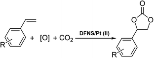
Cyclic carbonates can be used in many industrial fields such as lithium batteries, electrolytes in monomers and aprotic polar solvents and intermediates in organic synthesis. Currently, distinct cyclic carbonate combinations have been produced from carbon dioxide. Among them, carbon dioxide cycloaddition to epoxides is known as one of the common industrial methods.9,10 The direct synthesis of cyclic carbonates from olefins and carbon dioxide (CO2) by using oxidative carboxylation (refer to Scheme 1), which comprises the cycloaddition of alkene epoxidation and the addition of CO2 to the synthesized epoxide, can be a cost-efficient method because it requires low-cost and readily available raw materials, alkenes, and does not require epoxide separation.11–17 Olefin oxidative carboxylation was first presented in 1962. Nevertheless, the cycloaddition of CO2 to the epoxide ring still requires more studies and evaluations.18,19
 |
| | Scheme 1 Synthesis of cyclic carbonates through oxidative carboxylation of alkenes. | |
Due to their high specific surface area, reduced dimensionality and remarkable properties, two-dimensional (2D) nanosheets have become an ideal platform for the design of novel electrocatalysts for CO2 reduction.20–27 Borophene is a novel 2D material under active investigation due to its fascinating and diverse properties and potential.28 The properties of borophene can be enhanced and extended by alloying with other elements. This may provide new opportunities to design functional materials or catalysts.
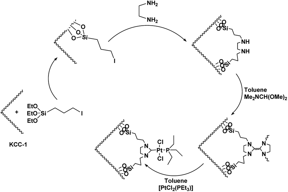
For organic transformations, octahedral Ru(II) and Ir(III) chromophores are commonly used as photocatalysts through outer sphere interactions to substrates. A group of scholars29 presented a type of Ir(III) complex that has a labile coordinated ligand for photochemical reactions through the interactions of the inner sphere. Pt(II) complexes30,31 with vacant axial coordination sites can provide greater opportunities in comparison to the octahedral Ir(III) and Ru(II) chromophores since these complexes can exhibit both inner sphere and outer sphere interactions with substrates. Nevertheless, a few investigations in terms of photo-induced organic transformation reactions using the complexes of Pt(II) are reported.32–35 In ref. 36, the scholars reported an approach for the difluoro alkylation of cinnamic acid by harnessing the photo-redox properties of the reductive capability of a Cu(I) catalyst and a Ru(II) complex. In this work, we showed that DFNS core–shell NPs could be efficiently functionalized using the Pt(II) complex,37–39 which is a novel recoverable heterogeneous nanocatalyst for the environmentally friendly, selective and efficient production of cyclic carbonates from olefins and CO2, as shown in Scheme 1.
Experimental
General procedure for the preparation of DFNS NPs
First, 2.5 g of tetraethyl orthosilicate (TEOS) was dissolved in a solution of 30 mL of cyclohexane and 1.5 mL of 1-pentanol. Then, 1 g of cetylpyridinium bromide (CPB) and 0.6 g of urea were dissolved in 30 mL of water and added to the previous solution. The resulting mixture was continuously stirred at room temperature for 45 min and heated at 120 °C for 5 h after placing it in a teflon-sealed autoclave. After silica was formed, it was centrifuged and isolated, washed with an acetone-deionized water mixture, and dried in a drying oven. Then, the material was calcined in air at 550 °C for 5 h.40
General approach for the DFNS/3-iodopropylsilane NP production
DFNS NPs (2 mmol) were added to 20 mL THF and ultrasonicated with 20 mmol of NaH. Then, 22 mmol of 3-iodopropyltriethoxysilane was added dropwise under the temperature of 25 °C and for 16 h, the mixture was stirred under the temperature of 60 °C. The resultant products were rinsed several times with deionized water and ethanol and dried in a vacuum oven for 2 h under the temperature of 60 °C.40
General approach for the DFNS/Pt(II) NP production
DFNS/3-iodoopropylsilane (20 mmol) and ethylenediamine (10 mmol) were stirred overnight in methanol. Diimine was collected as a white solid, filtrated and recrystallized in an alcohol–ether mixture. The diimine (10 mmol) was subsequently reduced by NaBH4 (30 mmol) in CH3OH (30 mL). The solution was then treated with 1 M HCl, and the organic phase was extracted with CH2Cl2 (3 × 30 mL). After drying over MgSO4 and evaporation, 1,2-bis(benzylamino)ethane was isolated as a solid. 1,2-Bis(benzylamino)ethane (0.10 mol) was dissolved in toluene (15 mL) and N,N-dimethylformamide dimethylacetal (0.12 mol) was added. The solution was placed in a water bath for 3 h in an inert atmosphere. At the end of this period, the mixture temperature was raised to 100 °C and allowed to stand for 1 h (Scheme 1). Toluene was removed by putting the mixture in vacuum, and the product was used in the synthesis of the complex, which was very sensitive to air humidity and oxygen. The electron-rich olefin (0.1 mol) was dissolved in toluene and then, [PtCl2(PEt3)2]2 (0.9 mol) was added and heated at 100 °C for 5 h. The solution was placed in vacuum to give a yellow solid. After washing with hexane, the product was crystallized in a dichloromethane–diethyl ether mixture (1![[thin space (1/6-em)]](https://www.rsc.org/images/entities/char_2009.gif) :2).
:2).
Catalytic reactions
The reaction was performed in a stainless steel autoclave (25 mL). Eight mg of catalyst, 10 mmol of olefin and 20 mmol of TBHP were placed in the stainless steel autoclave. The compound was stirred using a magnetic stirrer and then heated to a proper temperature by placing in a water bath. The reactor was purged with carbon dioxide several times and then charged by carbon dioxide. Then, the stainless autoclave was heated to a proper temperature and stirred for 10 hours. The reactor was cooled to 25 °C after the reaction was complete, and the residual CO2 was discharged slowly from the reactor. The reaction solution was examined using GC-MS and GC.
Results and discussion
As can be inferred from Scheme 1, DFNS core–shell NPs were fabricated using a simple approach and then functionalized using N-heterocyclic carbene platinum(II). We used different analysis techniques like TGA, TEM, BET, and SEM to characterize the DFNS/Pt(II) NPs produced by different methods (refer to Scheme 2).
 |
| | Scheme 2 Schematic illustration of the synthesis of KCC-1/Pt-NHC-Py NPs. | |
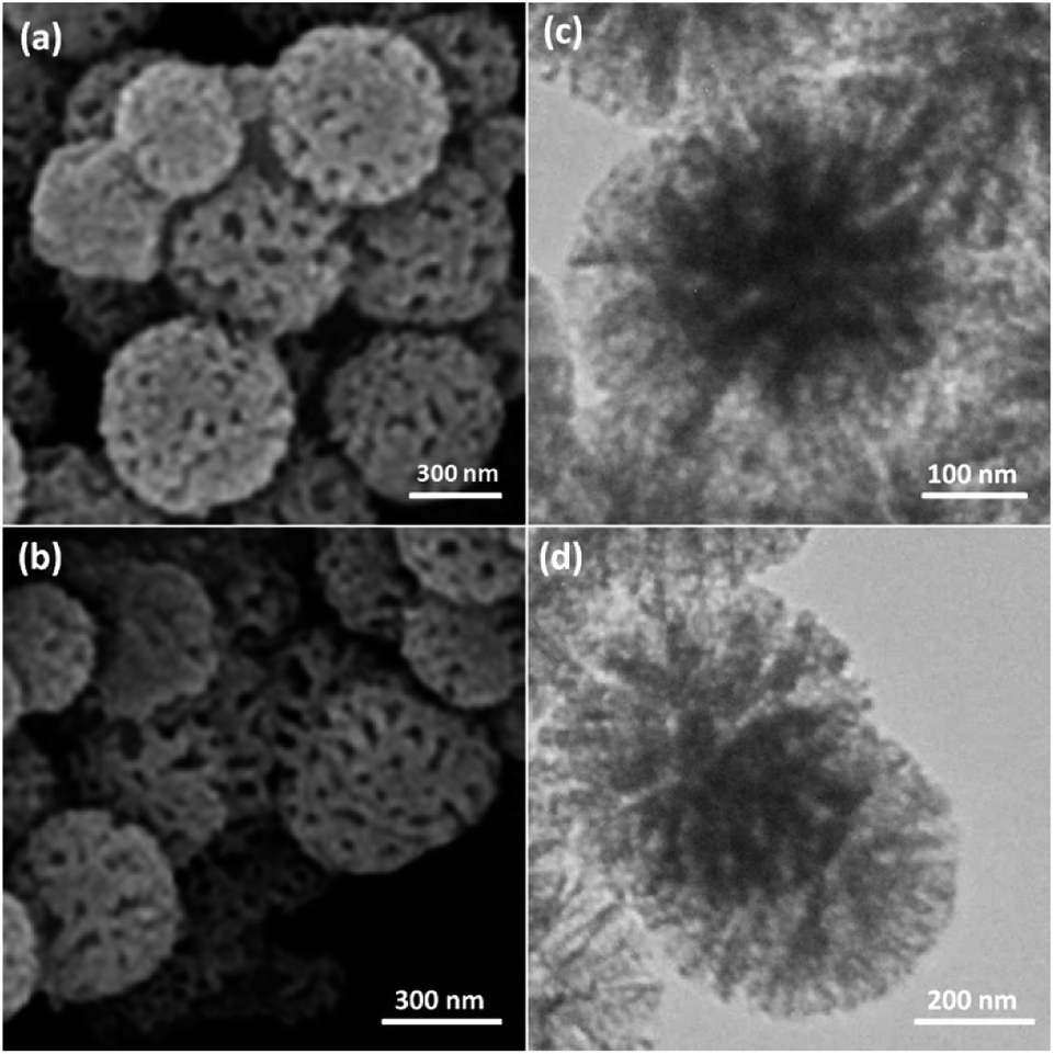
The structure and morphology of DFNS/Pt(II) and pristine DFNS NPs were subsequently characterized using TEM and FESEM. The FESEM image of the highly textured DFNS samples is shown in Fig. 1a. As observed, the samples possess spheres of uniform size with a wrinkled radial structure and diameters of ∼400 nm. As can be seen in Fig. 1c, the TEM image of DFNS indicates that the wrinkled fibers that have ∼10 nm thickness are radially regulated in three dimensions and grow out from the center of the spheres. In addition, cone-shaped open pores can be formed due to the overlapping of the wrinkled radial structure. The TEM and FESEM images indicated that the sphere was solid and composed of fibers. In addition, the fibers and also this open hierarchical channel structure provide better mass transfer of reactants and can enhance the availability of active sites. The TEM and FESEM images of DFNS/Pt(II) NPs indicated that after the modification of DFNS, the morphology did not vary (Fig. 1b and d). Fig. 2 shows the thermal conductivity of DFNS/Pt(II) NPs. The weight loss under 150 °C was ascribed to the elimination of the physisorbed and chemisorbed solvent on the surface of the DFNS/Pt(II) material. In the range of 180–350 °C, the weight loss is around 37.4 wt%, which may be due to the organic group derivatives.
 |
| | Fig. 1 FESEM images of DFNS NPs (a) and DFNS/Pt(II) NPs (b); TEM images of DFNS NPs (c) and DFNS/Pt(II) NPs (d). | |
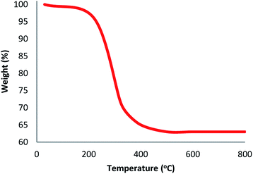 |
| | Fig. 2 TGA diagram of DFNS/Pt(II) NPs. | |
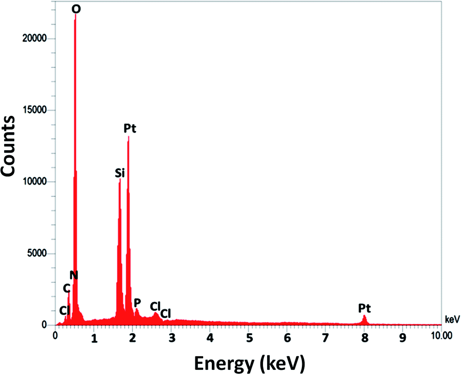
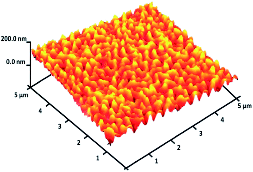
For DFNS, the BET surface area, BJH pore diameter, and total pore volume were obtained as 421 m2 g−1, 9.89 nm, and 1.34 cm3 g−1, respectively, while the values for DFNS/Pt (II) NPs were reduced to 348 m2 g−1, 7.01 nm and 1.11 cm3 g−1, respectively. The nitrogen sorption evaluation of DFNS/Pt(II) NPs additionally emphasized a uniform and ordered mesostructure with a reduction in pore volume, pore diameter, and surface area compared to that for pristine DFNS. The related pore volumes considerably decreased due to the functionalization using Pt-NHC-Si. This can be attributed to enhanced loading with the sensing probe that can occupy a large volume of the silica spheres (Table 1). As indicated in Fig. 3, the EDAX spectra provide clear evidence for chemical evaluation. O, Si, Cl, Pt, P, N, and C are demonstrated to be present in the DFNS/Pt(II) NPs. The level of roughness in these NPs was determined by analysing the samples with atomic force microscopy (AFM). The topographic scheme can be seen in Fig. 4. Fig. 4 shows that the more heighted region indicated by brighter yellowish white color increases by reducing T/W, proposing the enhancement in the level of roughness of the catalyst.
Table 1 Structural parameters of DFNS and DFNS/Pt(II) NPs determined from nitrogen sorption experiments
| Catalysts |
SBET (m2 g−1) |
Va (cm3 g−1) |
DBJH (nm) |
| DFNS |
421 |
1.34 |
9.89 |
| DFNS/Pt(II) |
348 |
1.11 |
7.01 |
 |
| | Fig. 3 The EDX spectra of DFNS/Pt(II) NPs. | |
 |
| | Fig. 4 Three-dimensional AFM image of DFNS/Pt(II) NPs. | |
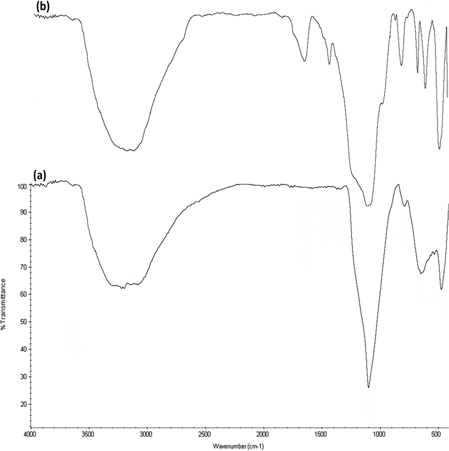
FTIR spectra (Fig. 5) prove the existence of organic groups in (a) the nanoparticles of DFNS along with (b) DFNS/Pt(II). The broad absorption peaks at 3389 cm−1 and 1101 cm−1 are attributed to OH and Si–O–Si asymmetric stretching, respectively, for DFNS/Pt(II). Fig. 5a shows two peaks at 802 cm−1 and 470 cm−1, corresponding to Si–O–Si symmetrical bending and stretching. The above-mentioned peaks also demonstrated the linkage of platinum(II) complexes on DFNS. The DFNS/Pt(II) composite shows bands at around 493, 802, and 1191 cm−1. A wide and powerful absorption band observed in the range of 3000–3500 cm−1 is related to the stretching vibrations of –OH.
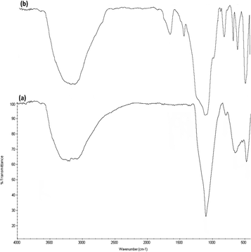 |
| | Fig. 5 FTIR spectra of (a) DFNS NPs and (b) DFNS/Pt(II) NPs. | |
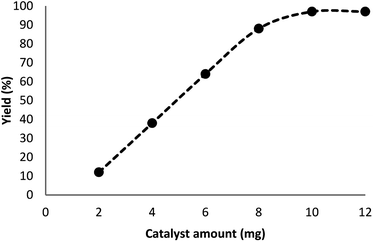
In our system, for the synthesis of cyclic carbonates catalyzed using DFNS/Pt(II) NPs, the conditions of the reaction are optimized with respect to olefin and CO2. The influence of different parameters like solvents and time on the model reaction can be observed from Table 2. Various solvents were utilized to study their effect on the synthesis of cyclic carbonates. Our outcomes proved that with the polar protic solvents like ethanol, methanol, isopropanol, and water, no product could be obtained. Polar aprotic solvents like EtOAc, DMSO, and DMF indicated mild efficiency for cross-coupling. In the present paper, our results proved that solvents are less efficient compared to common heating at solvent-free conditions. The efficiency of the cross-coupling reaction for carbonylation is higher in less polar solvents like toluene and/or anisole. The reaction was performed under optimum conditions in the presence of DFNS/Pt(II) nanoparticles (10 mg) for investigating the reaction progress. Note that the effect of reaction time was analyzed by GC. It was determined that excellent product yields were achieved after 5 h. The influence of distinct factors was analyzed for DFNS/Pt(II) NPs for the model reaction. Fig. 6 shows the effect of the amount of the catalyst, like other factors, on the yield. In addition, in the absence of the catalyst, low yields of the product of the cycloaddition reaction were obtained. The cyclic carbonate products demonstrated mild yields with the weighed quantities of DFNS/Pt(II) NPs equal to 2–8 mg. For the model reaction, the optimum value of DFNS/Pt(II) NPs was determined to be 10 mg.
Table 2 Synthesis of cyclic carbonates by DFNS/Pt(II) NPs in different solventsa
| Entry |
Solvent |
Time (h) |
Yieldb (%) |
| Reaction conditions: appropriate CO2 (3.0 MPa), olefin (10 mmol), DFNS/Pt(II) NPs (10 mg), TBHP (20 mmol), and solvent (10 mL), under reflux or at 100 °C. Isolated yields. |
| 1 |
H2O |
10 |
— |
| 2 |
i-PrOH |
10 |
— |
| 3 |
EtOH |
10 |
— |
| 4 |
MeOH |
10 |
— |
| 5 |
n-Hexane |
10 |
— |
| 6 |
Dioxane |
10 |
— |
| 7 |
DMF |
10 |
35 |
| 8 |
THF |
10 |
38 |
| 9 |
CHCl3 |
10 |
33 |
| 10 |
CH2Cl2 |
10 |
40 |
| 11 |
DMSO |
10 |
37 |
| 12 |
CH3CN |
10 |
29 |
| 13 |
EtOAc |
10 |
46 |
| 14 |
Toluene |
10 |
48 |
| 15 |
Anisole |
10 |
50 |
| 16 |
Solvent-free |
10 |
97 |
| 17 |
Solvent-free |
7 |
97 |
| 18 |
Solvent-free |
5 |
97 |
| 19 |
Solvent-free |
3 |
84 |
 |
| | Fig. 6 Effect of the increasing amount of DFNS/Pt(II) NPs on the yield of cyclic carbonate. | |
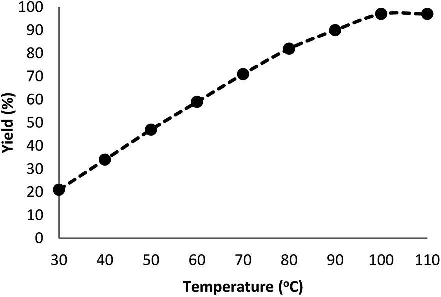
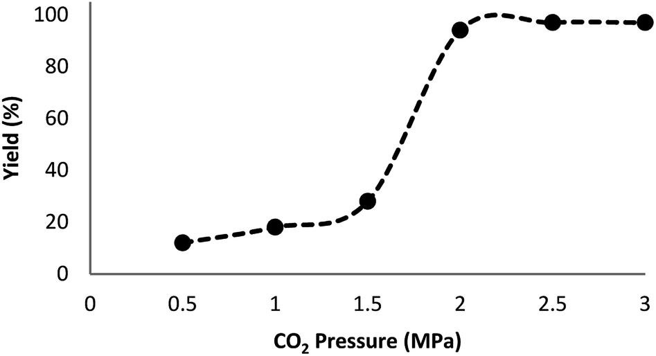
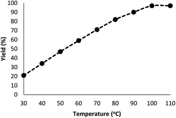
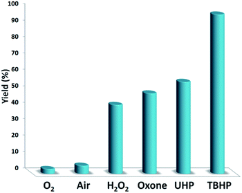
Fig. 7 indicates the effect of temperature on the yield of the reaction. As observed, under 3.0 MPa CO2 pressure at 80 °C within 5 h, the cyclic carbonate production enhances to around 97%. Nevertheless, a further increase in temperature caused slight reduction in the yield of the product because of the production of small amounts of specific by-products like olefin isomers. Hence, the most appropriate temperature in the case of the parallel reactions of CO2 and olefin was found to be about 100 °C. The pressure of CO2 had a considerable influence on the parallel reaction. Fig. 8 shows that the reaction rate is enhanced rapidly under pressures between 1.5 and 2.0 MPa. By taking previous works into consideration, it was found that enhancing the reaction pressure to 2.0 MPa was desirable for the cyclic production of carbonate. Hence, 2.0 MPa pressure of CO2 was detected as a special condition. During the first step of the reaction, the temperature of 80 °C for 4 h (10 mol%) was applied. Different oxidants were also utilized to enhance the yield of the product. The reaction yield was extremely sensitive to the base. To be precise, catalyst basicity is not the only parameter in determining activity. The highest yield was obtained by TBHP as an oxidant based on the results reported in Fig. 9.
 |
| | Fig. 7 Effect of temperature on the yield of cyclic carbonate. | |
 |
| | Fig. 8 Effect of CO2 pressure on the synthesis of cyclic carbonate. | |
 |
| | Fig. 9 The screening of the oxidant nature. | |
To further study the performance of the catalyst, various control measurements were obtained and the achieved results are demonstrated in Table 3. In the first step, a standard reaction performed utilizing DFNS indicated that no product was produced after the reaction time of 5 hours (refer to Table 3, entry 1). DFNS could not exhibit any catalytic activity at mild reaction conditions. In order to enhance the yield, the Pt(II) complex was added due to these disappointing outcomes. These results indicated that the reaction cycle was particularly catalyzed by using the Pt(II) complex. It should be noted that there is no considerable variation in the reaction yields when the reaction is performed in the presence of the Pt(II) complex (refer to Table 3, entries 3 and 5). The activity of the Pt(II) complex was also analyzed by changing the amount of Pt(II). The highest efficiency was achieved with 1.0 mol (%) of Pt(II), as can be observed in Table 3, entries 2–4. In addition, the Pt(II) complex could not be recovered and reused for the next runs. DFNS was utilized for preventing the dispersion of the Pt(II) complex and its easy separation.
Table 3 Influence of different catalysts for the cycloaddition of CO2a
| Entry |
Catalyst |
Catalyst loading |
Yieldb (%) |
| Reaction conditions: appropriate CO2 (2.0 MPa), aniline (1.0 mmol), and TBHP (20 mmol), under 100 °C. Isolated yield. |
| 1 |
DFNS |
10.0 mg |
— |
| 2 |
DFNS/Pt(II) |
10.0 mg (2.0 mol (%) of Pt(II)) |
97 |
| 3 |
DFNS/Pt(II) |
10.0 mg (1.0 mol (%) of Pt(II)) |
97 |
| 4 |
DFNS/Pt(II) |
10.0 mg (0.5 mol (%) of Pt(II)) |
73 |
| 5 |
Pt(II) complex |
10.0 mg |
95 |
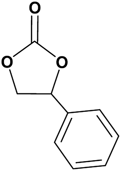
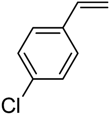
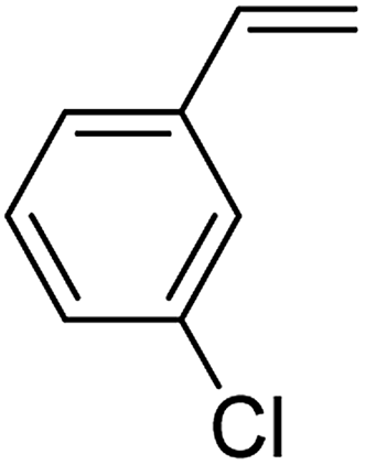
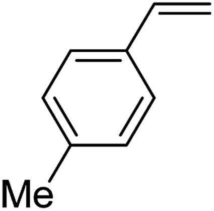
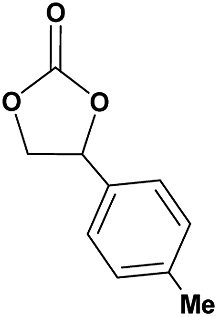
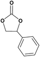
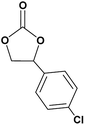
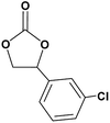
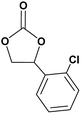
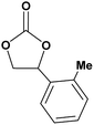
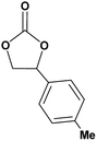
In this novel one-pot approach, in order to synthesize cyclic carbonates, distinct olefins were studied for the investigation of the substrate scope (refer to Table 4). For all the substrates shown in Table 4, the catalyst is active. In addition, aryl olefins bearing a para-chloro group were determined as excellent substrates, affording near-quantitative products. Moreover, aryl olefins and also ortho-chloro or meta groups were detected as excellent substrates. In contrast, an electron-donating group like methyl on the aryl group reduced the product yield.
Table 4 Cycloaddition of CO2 with terminal olefinsa
| Entry |
Olefins |
Products |
Yield (%) |
| Reaction conditions: appropriate CO2 (2.0 MPa), aniline (1.0 mmol), catalyst (10 mg), and TBHP (20 mmol), under 100 °C. |
| 1 |
 |
 |
97 |
| 2 |
 |
 |
93 |
| 3 |
 |
 |
95 |
| 4 |
 |
 |
90 |
| 5 |
 |
 |
96 |
| 6 |
 |
 |
98 |
The comparison of the catalytic activity of DFNS/Pt(II) with that of other recent catalysts used for the cycloaddition of CO2 can be seen in Table 5. The results showed that our catalyst system had the highest yield of the product for the same reaction time although a catalytic amount of a base was required, which confirmed that our catalyst was more active.
Table 5 Comparison of the catalytic efficiency of DFNS/Pt(II) NPs with that of various catalystsa
| Entry |
Catalyst |
Experimental conditions |
Average yield (%) |
| Reaction conditions: pyrrolidine in different temperatures, times, and solvents. |
| 1 |
[Ru(TPP)(O)2] |
DCM as solvent, 30 °C, 48 h |
53 (ref. 41) |
| 2 |
Manganese(III)-complex |
MeCN as solvent, 100 °C, 6 h |
32 (ref. 42) |
| 3 |
Co(acac)2-QPB@MCS |
MeCN as solvent, 100 °C, 10 h |
77 (ref. 43) |
| 4 |
[ZnW12O40]6−− |
Solvent-free, 50 °C, 96 h |
82 (ref. 44) |
| 5 |
Ti-MMM-E |
Solvent-free, 70 °C, 48 h |
49 (ref. 45) |
| 6 |
Fe(III)@MOF1 |
DCM as solvent, 50 °C, 24–48 h |
69 (ref. 46) |
| 7 |
NBS/DBU |
H2O as solvent, 60 °C, 3–6 h |
70 (ref. 47) |
| 8 |
[CnCmIm][HCO3] |
TBHP as solvent, 65 °C, 30 h |
63 (ref. 48) |
| 9 |
DFNS/Pt(II) |
Solvent-free, 100 °C, 5 h |
94 |
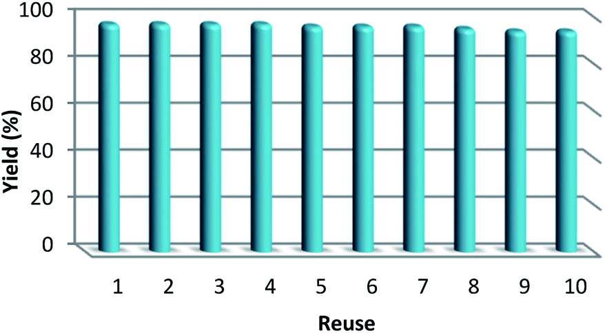
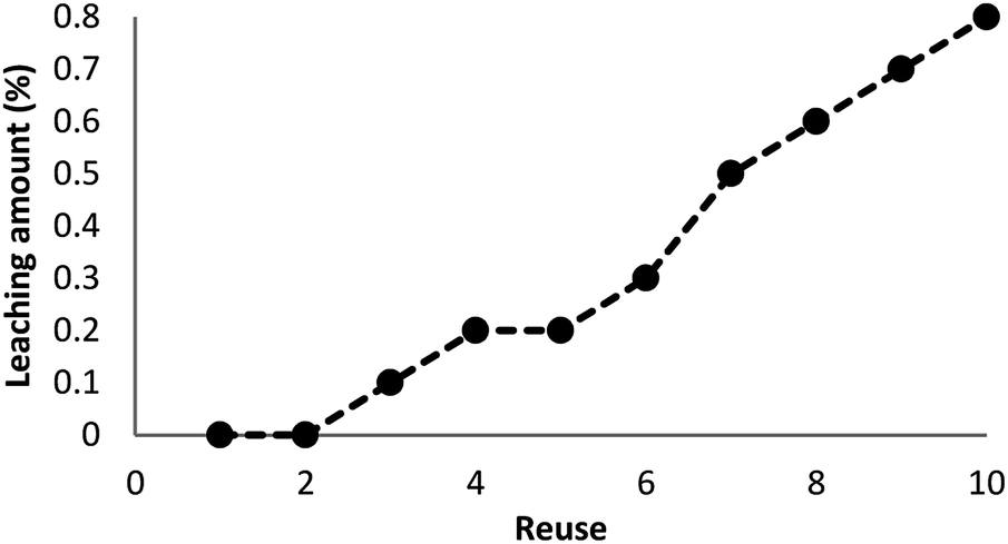
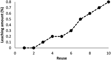
As can be seen in Fig. 10, after 10 runs, the catalyst may be reused. The yield of the cyclic carbonate product obtained in the 10th run was equal to 92% and was only 5% lower than that of the fresh catalyst (97%). Also, the leached metal amount in the solution for cyclic carbonate production for each run was investigated by utilizing ICP. Fig. 11 shows that the catalyst leached very little after 10 runs and after every run, just 0.8% of the metal leached.
 |
| | Fig. 10 The reusability of the catalyst for the synthesis of cyclic carbonate. | |
 |
| | Fig. 11 Recyclability of the catalyst for the synthesis of cyclic carbonate. | |
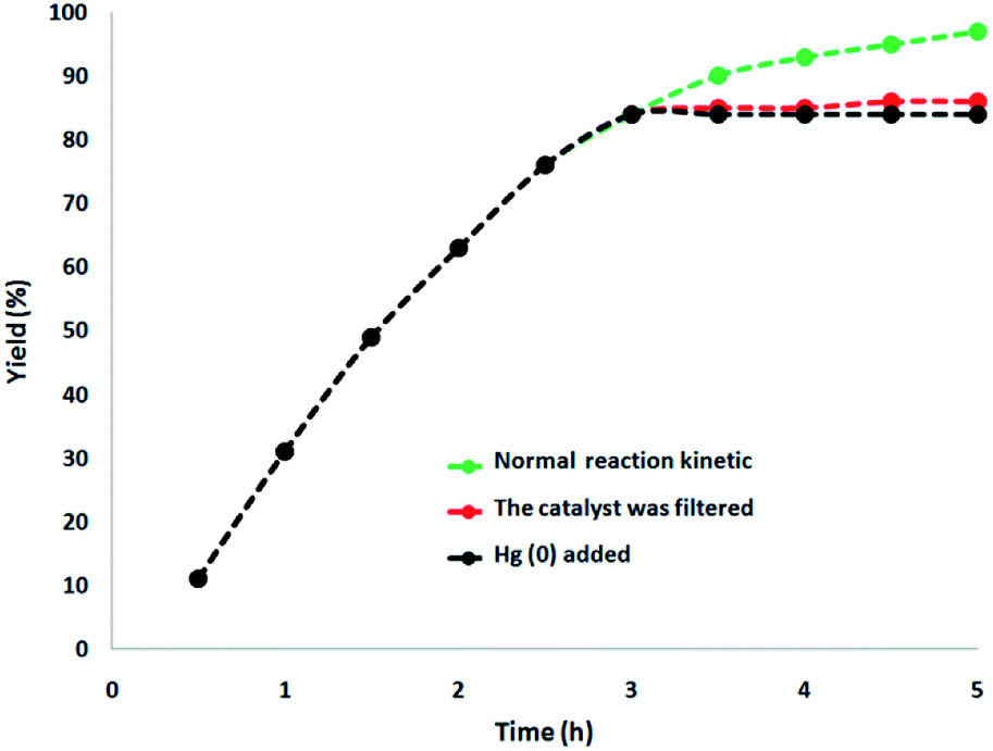
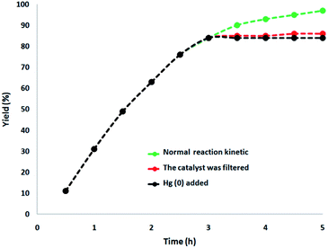
In this paper, a complete investigation of the heterogeneous nature of the catalyst was performed. Initially, for the synthesis of cyclic carbonate, we performed the hot filtration experiment at mild conditions and demonstrated that in situ, after reaching about 84%, the catalyst was removed after 3 h. In order to tolerate more reaction, the reactants were permissible. The results indicated that the remnants of the free catalyst after the reaction were fairly active after removing the heterogeneous catalyst, and the conversion equal to 86% was obtained after the cyclic carbonate production for 5 h. In the reaction, it was proved that the catalyst acted as a heterogeneous catalyst during the reaction, and only slight leaching occurred. Additionally, mercury poisoning evaluation was performed to prove the heterogeneous nature of the catalyst. Mercury(0) was imbibed as a metal (or utilizing synthesis). Moreover, it significantly deactivated the metal catalyst on the active surface and thus decreased the catalyst activity. Our investigations proved the heterogeneous nature of the catalyst. Under optimal conditions, this examination was performed for the aforementioned reaction model. After 3 h of the reaction, about 300 molar mercury was added to the reaction mixture and stirred. After 5 h of this reaction, due to the poisoning of the catalyst, no additional conversion was determined. As can be seen in Fig. 12, with the addition of Hg(0), the kinetics image of the reaction is clear. The negative outcomes created by the total heterogeneity experiments (i.e., hot filtration as well as Hg(0) poisoning) proposed that the solid catalyst is actually no acquirable and heterogeneous metal leaching done onto cyclic carbonate production.
 |
| | Fig. 12 Reaction kinetics, Hg(0) poisoning, and hot filtration studies for the synthesis of cyclic carbonate. | |
Conclusions
In this work, we synthesized the nanoparticles of DFNS/Pt(II) and the obtained catalyst was evaluated by BET, SEM, EDX, TGA, TEM, ICP, and FTIR analyses. In this regard, for the production of cyclic carbonates using the synthesized DFNS/Pt(II) NPs, a low-cost, non-toxic, and novel stable catalytic system was developed. The synthesized nanocomposite was heterogeneous and possessed the simplicity of the separation of the catalyst from the reaction mixture. For this reason, its catalytic activity does not vary in the reaction and the selectivity is maintained for 10 continuous runs. It is important to note that this nanocomposite does not need reactivation, which can mitigate economic and environmental problems. In addition, mercury poisoning along with hot filtration experiments affirmed negligible metal leaching and also the heterogeneous nature of the catalyst.
Conflicts of interest
There are no conflicts to declare.
Notes and references
- R. Zevenhoven, S. Eloneva and S. Teir, Catal. Today, 2006, 115, 73–79 CrossRef CAS.
- T. Sakakura, J. Choi and H. Yasuda, Chem. Rev., 2007, 107, 2365–2387 CrossRef CAS PubMed.
- M. Aresta and A. Dibenedetto, Dalton Trans., 2007, 2975–2992 RSC.
- L. N. He, J. Q. Wang and J. L. Wang, Pure Appl. Chem., 2009, 81, 2069–2080 CAS.
- T. Sakakura and K. Kohno, Chem. Commun., 2009, 1312–1330 RSC.
- M. M. Halmann and M. Steinberg, Greenhouse Gas Carbon Dioxide Mitigation: Science and Technology, Lewis Publishers, Boca Raton, Florida, 1999 Search PubMed.
- D. Bakker and A. Watson, Nature, 2001, 410, 765–766 CrossRef CAS PubMed.
- C. Song, Catal. Today, 2006, 115, 2–32 CrossRef CAS.
- X. B. Lu and D. J. Darensbourg, Chem. Soc. Rev., 2012, 41, 1462–1484 RSC.
- Q. W. Song, Z. H. Zhou and L. N. He, Green Chem., 2017, 19, 3707–3728 RSC.
- D. Xiang, X. Liu, J. Sun, F. S. Xiao and J. Sun, Catal. Today, 2009, 148, 383–388 CrossRef CAS.
- M. Aresta and E. Quaranta, J. Mol. Catal., 1987, 41, 355–359 CrossRef CAS.
- M. Aresta, A. Dibenedetto and I. Tommasi, Appl. Organomet. Chem., 2000, 14, 799–802 CrossRef CAS.
- D. Bai and H. Jing, Green Chem., 2010, 12, 39–41 RSC.
- J. M. Sun, S. Fujita, B. M. Bhanage and M. Arai, Catal. Today, 2004, 93–95, 383–388 CrossRef CAS.
- J. M. Sun, S. Fujita, B. M. Bhanage and M. Arai, Catal. Commun., 2004, 5, 83–87 CrossRef CAS.
- S. Fukuoka, M. Kawamura, K. Komiya, M. Tojo, H. Hachiya, K. Hasegawa, M. Aminaka, H. Okamoto, I. Fukawa and S. Konno, Green Chem., 2003, 5, 497–507 RSC.
- G. W. Coates and D. R. Moore, Angew. Chem., Int. Ed., 2004, 43, 6618–6639 CrossRef CAS PubMed.
- M. North, R. Pasquale and C. Young, Green Chem., 2010, 12, 1514–1539 RSC.
- B. Song, Y. Zhou, H. M. Yang, J. H. Liao, L. M. Yang, X. B. Yang and E. Ganz, J. Am. Chem. Soc., 2019, 141, 3630–3640 CrossRef CAS PubMed.
- L. M. Yang, V. Bačić, I. A. Popov, A. I. Boldyrev, T. Heine, T. Frauenheim and E. Ganz, J. Am. Chem. Soc., 2015, 137, 2757–2762 CrossRef CAS PubMed.
- J. H. Liu, L. M. Yang and E. Ganz, ACS Sustainable Chem. Eng., 2018, 6, 15494–15502 CrossRef CAS.
- J. H. Liu, L. M. Yang and E. Ganz, J. Mater. Chem. A, 2019, 7, 3805–3814 RSC.
- J. H. Liu, L. M. Yang and E. Ganz, J. Mater. Chem. A, 2019, 7, 11944–11952 RSC.
- J. H. Liu, L. M. Yang and E. Ganz, RSC Adv., 2019, 9, 27710–27719 RSC.
- Y. Yoo, G. D. Park and Y. C. Kang, Energy Environ. Mater., 2019, 2, 193–200 CrossRef.
- L. Xu, L. M. Yang and E. Ganz, Theor. Chem. Acc., 2018, 137, 98 Search PubMed.
- Y. Liu, L. M. Yang and E. Ganz, Condens. Matter, 2019, 4, 65 Search PubMed.
- H. Huo, X. Shen, C. Wang, L. Zhang, P. Rose, L. A. Chen, K. Harms, M. Marsch, G. Hilt and E. Meggers, Nature, 2014, 515, 100–103 CrossRef CAS PubMed.
- D. M. Roundhill, H. B. Gray and C. M. Che, Acc. Chem. Res., 1989, 22, 55–61 CrossRef CAS.
- R. McGuire Jr, M. C. McGuire and D. R. McMillin, Coord. Chem. Rev., 2010, 254, 2574–2583 CrossRef.
- J. J. Zhong, Q. Y. Meng, G. X. Wang, Q. Liu, B. Chen, K. Feng, C. H. Tung and L. Z. Wu, Chem.–Eur. J., 2013, 19, 6443–6450 CrossRef CAS PubMed.
- W. J. Choi, S. Choi, K. Ohkubo, S. Fukuzumi, E. J. Cho and Y. You, Chem. Sci., 2015, 6, 1454–1464 RSC.
- P. K. Chow, G. Cheng, G. S. M. Tong, W. P. To, W. L. Kwong, K. H. Low, C. C. Kwok, C. Ma and C. M. Che, Angew. Chem., Int. Ed., 2015, 54, 2084–2089 CrossRef CAS PubMed.
- F. Julia and P. GonzálezHerrero, J. Am. Chem. Soc., 2016, 138, 5276–5282 CrossRef CAS PubMed.
- H. R. Zhang, D. Q. Chen, Y. P. Han, Y. F. Qiu, D. P. Jin and X. Y. Liu, Chem. Commun., 2016, 52, 11827–11830 RSC.
- S. M. Sadeghzadeh, RSC Adv., 2016, 6, 75973–75980 RSC.
- S. M. Sadeghzadeh, R. Zhiani, M. Khoobi and S. Emrani, Microporous Mesoporous Mater., 2018, 257, 147–153 CrossRef CAS.
- S. M. Sadeghzadeh, R. Zhiani and S. Emrani, Appl. Organomet. Chem., 2018, 32, e3941 CrossRef.
- S. M. Sadeghzadeh, R. Zhiani and S. Emrani, RSC Adv., 2017, 7, 24885–24894 RSC.
- D. Bai and H. Jing, Green Chem., 2010, 12, 39–41 RSC.
- P. Ramidi, C. M. Felton, B. P. Subedi, H. Zhou, Z. R. Tian, Y. Gartia, B. S. Pierce and A. Ghosh, J. CO2 Util., 2015, 9, 48–57 CrossRef CAS.
- S. Kumar, N. Singhal, R. K. Singh, P. Gupta, R. Singh and S. L. Jain, Dalton Trans., 2015, 44, 11860–11866 RSC.
- Q. Han, B. Qi, W. Ren, C. He, J. Niu and C. Duan, Nat. Commun., 2015, 6, 10007 CrossRef PubMed.
- N. V. Maksimchuk, I. D. Ivanchikova, A. B. Ayupov and O. A. Kholdeeva, Appl. Catal., B, 2016, 181, 363–370 CrossRef CAS.
- N. Sharma, S. S. Dhankhar, S. Kumar, T. D. Kumar and C. M. Nagaraja, Chem.–Eur. J., 2018, 24, 16662–16669 CrossRef CAS PubMed.
- N. Eghbali and C.-J. Li, Green Chem., 2007, 9, 213–215 RSC.
- J. Liu, G. Yang, Y. Liu, D. Wu, X. Hu and Z. Zhang, Green Chem., 2019, 21, 3834–3838 RSC.
|
| This journal is © The Royal Society of Chemistry 2020 |
Click here to see how this site uses Cookies. View our privacy policy here. 
 Open Access Article
 This Open Access Article is licensed under a Creative Commons Attribution-Non Commercial 3.0 Unported Licence
 *b,
Alireza Motavalizadehkakhky
*b,
Alireza Motavalizadehkakhky