 Open Access Article
Creative Commons Attribution 3.0 Unported Licence
Epitaxial synthesis of Ni–MoS2/Ti3C2Tx MXene heterostructures for hydrodesulfurization†
Mari Vinoba *,
R. Navvamani and
Hanadi Al-Sheeha
Petroleum Research Center, Kuwait Institute for Scientific Research, Kuwait. E-mail: vmari@kisr.edu.kw; vinoba76@gmail.com
First published on 26th March 2020
Abstract
Hierarchical structures of 2D layered Ti3C2Tx MXene hold potential for a range of applications. In this study, catalysts comprising few-layered MoS2 with Ti3C2Tx have been formulated for hydrodesulfurization (HDS). The support Ti3C2Tx was derived from MAX phases (Ti3AlC2) via a liquid-phase exfoliation process, while MoS2 was obtained from synthesized aqueous ammonium tetrathiomolybdate (ATM). Furthermore, a series of catalysts with different architectures was synthesized by confinement of ATM and/or the promoter Ni in Ti3C2Tx at different mole ratios, through a thermal conversion process. The synthesized MoS2/Ti3C2Tx and Ni–MoS2/Ti3C2Tx catalysts were characterized using X-ray diffraction (XRD), Brunauer–Emmett–Teller (BET), scanning electron microscopy coupled with energy dispersive X-ray spectroscopy (SEM-EDS), high-resolution transmission electron microscopy (HRTEM), and temperature-programmed reduction (TPR) measurements. The number of MoS2 layers formed on the Ti3C2Tx support was calculated using Raman spectroscopy. The heterostructured few-layered MoS2/Ti3C2Tx catalysts were applied in sulfur removal efficiency experiments involving thiophene. The active MoS2 sites confined by the Ti3C2Tx enhanced hydrogen activation by proton saturation, and the electron charge stabilized the sulfur atom to facilitate hydrogenation reactions, leading to predominant formation of C4 hydrocarbons. The Ni–MoS2/Ti3C2Tx showed the best activity at a promoter molar ratio of 0.3 when compared to the other catalysts. In particular, it is evident from the results that ATM and Ti3C2Tx are potential materials for the in situ fabrication of hierarchical few-layered MoS2/Ti3C2Tx catalysts for enhancing hydrodesulfurization activity in clean fuel production.
Introduction
The current socio-economic climate demands control over production costs, innovative technologies, zero pollution to life-giving sources, and “no waste” management in petroleum refineries. Many factors affect the goals of petroleum refineries, and one of these is the effect of sulfur emitted from automotive fuels to the environment; thus environmental protection agencies have imposed stringent regulations on sulfur levels in transportation fuels.1,2 Over recent years, many conventional supported and unsupported NiMo and CoMo-sulfide catalysts have been employed in the hydrodesulfurization (HDS) reaction.3,4 The supported catalysts show more stability, offer enhanced dispersion of active metal sites on the surface, and are more durable than unsupported catalysts. The prominent activity of hydrotreating catalysts depends on the potential of the active sites, and the structure and textural characteristics of the supports.5–7 Generally, alumina is used as a support as it is economical and possesses unique physicochemical properties. However, the conventional sulfidation of Mo-oxide on alumina with H2S treatment occurs at a high temperature, which may lead to the formation of a mixture of Mo-sulfides/oxides, and the inhibition of HDS activity due to strong metal–alumina interactions.8–10 Furthermore, promoted hydrotreating catalysts show enhanced HDS activity due to promoter atoms which are dispersed on the MoS2 edges of the square pyramidal structure in the same plane as the Mo atoms.11,12 It is reported that the morphology of promoter–Mo–sulfur catalysts with supports is characterized either by a highly dispersed single-layer structure that strongly interacts with the support and has low sulfur coordination with Mo and the promoter (Type-I) or by a less dispersed few-layered structure that weakly interacts with the support due to complete sulfidation and has higher sulfur coordination to Mo and the promoter (Type-II). Due to the structural properties, it has been reported in previous studies that the Type-II structure reveals higher HDS activity than the Type-I structure.13,14 Notably, a few reports have described the use of ammonium thiometallates as precursors for the preparation of active metal-sulfide HDS catalysts due to their unique electronic structures and chemical reactivity.15,16 Currently, the thermal conversion of ammonium thiomolybdate at a low temperature is used to produce uniformly active MoS2 dispersed on supported HDS catalysts; this could provide a more economical method than conventional sulfidation of molybdenum oxides. Moreover, the thiomolybdate precursor contains sulfur bonded to Mo in a tetrahedral coordination, which undergoes a topotactic reaction during the thermal conversion; as a result, the c-axis of sulfide is retained in the precursor.17In recent years, metal carbides have played a significant role in the formulation of new generation catalysts with novel support systems that can overcome the inhibition of HDS efficiency due to strong metal–support interactions. This hybrid system composed of a support and active metals enhances the removal of sulfur through the breaking of the ring S–C bonds in thiophene derivatives.18,19 In this regard, transition metal carbides and nitrides that possess significantly altered physical and chemical properties have been recognized as encouraging support materials for crude oil hydroprocessing due to their excellent performance and stability in HDS processes.7,20 Transition metal carbides have attracted attention as prospective catalysts for use in the HDS process as they exhibit hydrogenating properties similar to those of noble metals,21 and at the same time, they are sulfur-tolerant.22 Currently, however, researchers are giving more attention to the new family of two-dimensional (2D) transition metal carbides and nitrides (MXenes) (where M refers to early transition metals (groups 13 and 14) and X corresponds to carbon and/or nitrogen) because of their unique structure, mechanical, optical and electronic properties, large specific surface areas, surface hydrophilicity, and tunable compositions.23 MXenes (Mn+1XnTx) (where Tx denotes surface terminated functional groups (–F, –OH, and –O)) are derived from MAX phases (Mn+1AXn) (where A stands for mostly IIIA or IVA group elements) by selective etching of the A layer. The ordered MXenes comprise few atoms that have n layers of sandwiched Ti–C–Ti sheets. MXene-based hybrid materials play a vital role in a wide range of applications such as energy storage,24 hydrogen storage,25 catalysis,26 sensing,27 water purification,28 and gas separation29 due to the attached surface anion functional groups, which provide hydrophilic surfaces and enhance the dispersion of the catalysts.
Based on the above, the MXene Ti3C2Tx was derived by etching the Al-layer from a MAX compound Ti3AlC2. A few-layered MoS2 catalyst was developed by combining the active metal and promoter on the MXene support (Ni–Mo–S/Ti3C2Tx). It was investigated for thiophene HDS at a low hydrogen pressure and reaction temperature. Synthesized ammonium thiomolybdate (ATM) was used as a precursor for the preparation of the MoS2 catalyst. The few-layered MoS2 was derived by controlled calcination in an inert medium in a rotary furnace.
Experimental
Preparation of Ti3C2Tx MXene and ATM solution
Ti3AlC2 powder was dispersed slowly in 30% HF solution in a ratio of 1![[thin space (1/6-em)]](https://www.rsc.org/images/entities/char_2009.gif) :
:![[thin space (1/6-em)]](https://www.rsc.org/images/entities/char_2009.gif) 10 (Ti3AlC2
10 (Ti3AlC2![[thin space (1/6-em)]](https://www.rsc.org/images/entities/char_2009.gif) :
:![[thin space (1/6-em)]](https://www.rsc.org/images/entities/char_2009.gif) HF) (Caution: exothermic reaction) with continuous stirring at room temperature for 48 h. This exfoliated the MXene layers by etching the aluminum. The de-aluminated product MXene (Ti3C2Tx) was washed in water and centrifuged several times until the pH reached neutral. Then it was dried at 60 °C for 12 h.30 A stock solution of ATM was prepared by dissolving ammonium heptamolybdate (15.8 mmol) in a mixture of ammonium hydroxide and water.31 The mixture was purged with 10% hydrogen sulfide (H2S/Ar) at 100 mL min−1 for sulfidation at room temperature for 2 h. The temperature was gradually increased to 60 °C with continuous H2S purging until a dark red stock solution was obtained, and this was used as a precursor for MoS2.
HF) (Caution: exothermic reaction) with continuous stirring at room temperature for 48 h. This exfoliated the MXene layers by etching the aluminum. The de-aluminated product MXene (Ti3C2Tx) was washed in water and centrifuged several times until the pH reached neutral. Then it was dried at 60 °C for 12 h.30 A stock solution of ATM was prepared by dissolving ammonium heptamolybdate (15.8 mmol) in a mixture of ammonium hydroxide and water.31 The mixture was purged with 10% hydrogen sulfide (H2S/Ar) at 100 mL min−1 for sulfidation at room temperature for 2 h. The temperature was gradually increased to 60 °C with continuous H2S purging until a dark red stock solution was obtained, and this was used as a precursor for MoS2.
Formulation of the MoS2/Ti3C2Tx MXene catalysts
The incipient wetness impregnation technique was used to prepare two sets of Ti3C2Tx supported target catalysts. One set (termed AMA) was prepared with active MoS2 on Ti3C2Tx, and the other (termed NAMA) was prepared using a Ni promoter with MoS2 on Ti3C2Tx. A series of AMA catalysts were formulated at different ratios of Mo (6, 9, and 12 wt%) by dispersion of the ATM stock solution in the Ti3C2Tx support. These materials were dried and calcined in the rotary furnace under N2 and are denoted as AMA-1, AMA-2, and AMA-3, respectively. The NAMA catalysts were prepared by a stepwise impregnation method. First, ATM solutions (6, 9, and 12 wt% Mo) were impregnated on MXene, as above, and then the samples were impregnated with nickel nitrate. The Ni/(Ni + Mo) ratios for the samples with 6, 9 and 12 wt% Mo were maintained at 0.39, 0.30, and 0.24, respectively. Subsequently, the materials were calcined in an inert medium to give the NAMA catalysts denoted as NAMA-1, NAMA-2, and NAMA-3, respectively. The above-synthesized series of AMA and NAMA catalysts were next treated with 10% H2S (balanced H2) in a reactor at 375 °C for 4 h, and then the temperature was reduced to 350 °C for the thiophene HDS reactions; the corresponding catalysts are denoted as S-AMA and S-NAMA, respectively. All the synthesized materials were characterized and investigated for thiophene HDS activity.Catalytic properties of the MXene-based catalysts
The HDS activity of each synthesized catalyst was assessed in a fixed glass reactor associated with a thiophene saturator system. Hydrogen was bubbled through thiophene to attain an equilibrium between liquid thiophene and its vapor, and then the produced vent gas mixture (H2 + thiophene) was used as a feed.32 The thiophene concentration in the reactor inlet was quantified from its vapor pressure using the Antoine eqn (1); the molar fraction of thiophene + hydrogen is given by eqn (2).
ln![[thin space (1/6-em)]](https://www.rsc.org/images/entities/char_2009.gif) Psat (mm Hg) = A − B/(C + Tsat) Psat (mm Hg) = A − B/(C + Tsat)
| (1) |
| Xthiophene = Psat/P | (2) |
The desired amount of catalyst was placed in the glass reactor and purged with hydrogen-containing thiophene vapor at 50 mL min−1 at 350 °C. The reactor outlet was connected to an online gas chromatograph (GC) for the quantification of C1–C4 hydrocarbon products and unreacted thiophene. The GC was calibrated with Agilent refinery gas mixture P/N 5190-0519.31 The data were recorded at periodic intervals to evaluate the conversion rate and product selectivity. The molar flow of thiophene into the reactor (3) and HDS conversion rate (4) were calculated as follows:
| Fthiophene = Psat × V/RTsat | (3) |
| Conversion rate (ν) = Fthiophene × α/m | (4) |
Results and discussion
Characterization of the catalysts
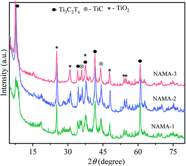
The XRD patterns of the pristine MAX phase (Ti3AlC2), and MXene (Ti3C2Tx) are shown in Fig. S1.† Ti3AlC2 displayed characteristic intense peaks at 2θ = 9.54°, 19.17°, 33.99°, 38.99° and 40.89° corresponding to the planes (002), (004), (101), (104) and (105), respectively. All the 2θ values agreed with those in JCPDS no. 52-0875, confirming the purity of Ti3AlC2.34,35 In the MXene pattern, the most intense peak of Ti3AlC2 located at 38.99° (104) was completely absent due to the HF-etching process that had removed the entire atomic aluminum layer. Also, the Al-layer exfoliated MXene exhibited shifts in two peaks toward lower angles, from 9.54° and 19.17° to 9.10° (002) and 18.50° (004). At the same time, two new peaks emerged at 2θ = 27.94° (008), and 60.78° (110),25,36 which confirmed the transformation of Ti3AlC2 to Ti3C2Tx MXene.The XRD patterns of the AMA (Fig. S2†) and NAMA (Fig. 1) catalysts revealed no individual MoS2 peaks (JCPDS 03-065-0160) due to the formation of nanocrystalline MoS2 on Ti3C2Tx.37 Furthermore, the (002) peaks of AMA-1, AMA-2, AMA-3, NAMA-1, NAMA-2, and NAMA-3 catalysts were downshifted in comparison to that of Ti3C2Tx (9.10°) to ∼7.4°–8.3°. These shifts towards lower 2θ values confirmed the enlarged d-spacing of Ti3C2Tx due to the effective intercalation of MoS2 between the Ti3C2Tx layers in the prepared catalysts. In addition, the diffraction peaks of Ti3C2Tx were retained at their original 2θ positions of 37.6° and 60.78° (002); this indicated the persistence of Ti3C2Tx in the AMA and NAMA catalysts.38 The XRD patterns of the NAMA catalysts exhibited new peaks corresponding to TiC and TiO2 which could be attributed to the minor conversion of Ti3C2Tx to TiC and TiO2 in the presence of the promoter salt during the calcination, but these impurities were relatively very low in the AMA catalysts.
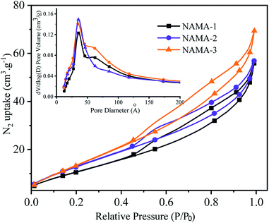
The N2 adsorption–desorption isotherms of the AMA (Fig. S3†) and NAMA (Fig. 2) catalysts show type H3 hysteresis. The specific surface areas of Ti3AlC2 and Ti3C2Tx calculated using the Brunauer–Emmett–Teller (BET) method were found to be 4.2 and 13.5 m2 g−1, respectively. All of the prepared catalysts showed increasing specific surface areas when the Mo loading was increased from 6 to 12%. For example, the BET surface areas of AMA-1, AMA-2, AMA-3, were 34.5, 42.7, and 47.3 m2 g−1, respectively, and the same trend was observed for NAMA-1, NAMA-2, and NAMA-3 which had surface areas of 45.1, 55.8 and 62.8 m2 g−1, respectively. The higher surface areas of the catalysts compared to the support (Ti3C2Tx) were most likely due to the intercalation of MoS2 between the Ti3C2Tx interlayers and its anchoring on the surfaces along with the partial delamination of the Ti3C2Tx layers. In addition, the NAMA catalysts had higher surface areas than the AMA type catalysts due to the improved crystallinity of the nickel promoter as well as the MoS2 between the Ti3C2Tx interlayers. The pore size distributions indicate that the pores of the AMA and NAMA catalysts were in the mesoporous range (20–500 Å), and results show a decreasing trend from 50 to 40 Å with an increase in Mo loading from 6 to 12 wt%. Thus, the better textural properties of the AMA and NAMA catalysts should be beneficial for enhancing catalyst contact area, and facilitating the access of the reactant to the active MoS2 sites on the catalytic surfaces.
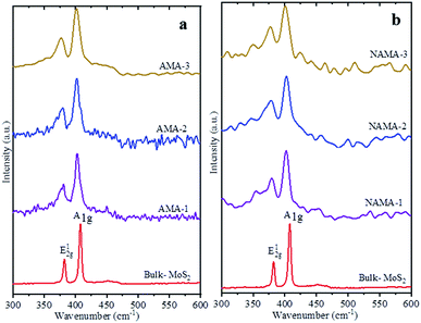
Raman spectra of the few-layered MoS2/MXene catalysts exhibited two characteristic MoS2 vibration modes, as shown in Fig. 3. The frequency displacement between the in-plane and out-of-plane Mo–S phonon modes, corresponding to the E12g vibration, softened (red-shifted), while the A1g vibration stiffened (blue-shifted) in the catalysts.38,39 These two modes are thickness-dependent and indicate the number of layers.40 Typically, the difference in vibration modes of monolayer, few-layer, and bulk crystal MoS2 are 18, 19–24, and >25 cm−1, respectively. The few-layered MoS2 catalysts (AMA and NAMA) were successfully derived from the thermal conversion of ATM, and displayed active modes at ∼400 cm−1 (A1g) and ∼378 cm−1 (E12g); the asymmetric stretching peak at 477 cm−1, and the symmetric vibration at 456 cm−1 of the Mo![[double bond, length as m-dash]](https://www.rsc.org/images/entities/char_e001.gif) S bond in tetrahedral [MoS4]2− (ref. 31) were not detected. The frequency differences between the vibration modes for AMA-1, AMA-2 and AMA-3 were 22.0, 22.5, and 22.9 cm−1, respectively, while NANA-1, NAMA-2 and NAMA-3 had differences of 22.2, 22.5, and 23.1 cm−1, respectively. In contrast, the frequency difference between the E12g and A1g modes for bulk MoS2 was 25.5 cm−1. Thus, the Raman spectroscopy results for the catalysts illustrated differences between the two vibration modes of ∼22.5 cm−1, which indicated the successful formation of few-layered MoS2 on MXene.
S bond in tetrahedral [MoS4]2− (ref. 31) were not detected. The frequency differences between the vibration modes for AMA-1, AMA-2 and AMA-3 were 22.0, 22.5, and 22.9 cm−1, respectively, while NANA-1, NAMA-2 and NAMA-3 had differences of 22.2, 22.5, and 23.1 cm−1, respectively. In contrast, the frequency difference between the E12g and A1g modes for bulk MoS2 was 25.5 cm−1. Thus, the Raman spectroscopy results for the catalysts illustrated differences between the two vibration modes of ∼22.5 cm−1, which indicated the successful formation of few-layered MoS2 on MXene.
The XPS technique was used to investigate the surface electronic states of the available elements in the NAMA-2 catalyst and their terminal groups. The XPS survey spectrum revealed Ni, Mo, S, Ti, C, O, and F elements (Fig. 4a) and so corresponding high-resolution XPS spectra were obtained for Ni 2p, Mo 3d, S 2p, Ti 2p, C 1s, O 1s, and F 1s (Fig. 4b). The photoemission of the Ti 2p region in the Ni-promoted MoS2/Ti3C2Tx (NAMA-2) catalyst was deconvoluted and the peaks were fitted, as shown in Fig. 4b. The Ti 2p spectrum showed three peaks corresponding to O or OH terminated groups placed at binding energies of 454.9, 456.0, and 457.6 eV, and corresponding to Ti–C, Ti2+–C and Ti4+–C, respectively.38,41
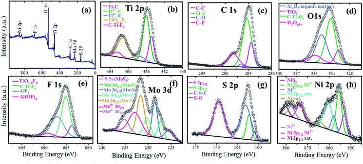 | ||
| Fig. 4 XPS spectra of the NAMA-2 catalyst: full survey spectrum (a), and core level spectra of Ti 2p (b), C 1s (c), O 1s (d), F 1s (e), Mo 3d (f), S 2p (g), and Ni 2p (h). | ||
The C 1s spectrum of the NAMA-2 catalyst was deconvoluted to four peaks, with the major peak at +284.7 eV attributed to adventitious carbon (C–C) caused by material exposure to the atmosphere. The other peaks at 283.2, 285.8, and 287.4 eV corresponded to Ti–C bonds, surface C–O bonds, and C–F groups, respectively.42,43 The O 1s profile for the NAMA-2 catalyst was deconvoluted to four peaks located at 529.6, 531.2, 532.8, and 533.8 eV and assigned to TiO2, C–Ti–Ox, Al2O3, and H2O(ads). The binding energies of some atoms and groups overlapped with many other peaks due to surface organic contamination. The peak value of C–Ti–O (531.2 eV) was close to that for O atoms near to vacancies in TiO2 (531.5 eV). The strongly adsorbed water molecules on the surface, and OH groups at bridging sites of titania appeared at the same binding energy of 533.8 eV. The F 1s spectrum was well fitted43 to four peaks, of which the main peak for C–Ti–Fx was located at 685.1 eV, and the peaks for TiO2−xFx, AlFx, and Al(OF)x appeared at 683.8, 687.0 and 689.1 eV, respectively.
The Mo 3d region displayed seven peaks, as shown in Fig. 4f. The two peaks for Mo–S bonds located at 228.9 and 231.9 eV corresponded to Mo4+ 3d5/2 and Mo4+ 3d3/2, respectively.39,41 Furthermore, a peak was observed at a lower binding energy (225.3 eV) which could be ascribed to S 2s of MoS2. The peaks of Mo–C bonds appeared at 227.7 and 231.8 eV, corresponding to Mo 3d5/2 and Mo 3d3/2, respectively. The higher oxidation state Mo6+ was also noticed and could be attributed to the partial oxidation of the Mo edges in MoS2 from the Mo4+ to Mo6+ state (MoO3 and MoO42−) when exposed to the air. The peaks of Mo6+ located at 232.8 and 235.2 eV were ascribed to Mo6+ 3d5/2 and Mo6+ 3d3/2. The S 2p3/2 and S 2p1/2 peaks in the S 2p spectrum at 161.5 and 162.9 eV, respectively, corresponded to a doublet of S2− species in MoS2 (Fig. 4g). The peak at 163.4 eV, ascribed to C–S–C bonds, was due to the strong intercalation of MoS2 into the Ti3C2Tx support. Another peak was observed at a high binding energy (169.4 eV), which coincided with the S–O bond, and might be due to the partial oxidation of the S edges in MoS2 by exposure to the atmosphere. The Ni 2p spectrum of the NAMA catalyst (Fig. 4h) showed two sets of doublets from Ni 2p3/2 (NiMoS phase) and Ni 2p1/2 at 855.4 and 873.2 eV, respectively, as well as satellite (Sat.) peaks at 860.7 and 880.0 eV, which were ascribed to the Ni2+ valence state.43 The other two peaks at 857.6 and 873.8 eV corresponded to Ni3+ (Ni2O3). In the ATM decomposition process, MoS42− converts to MoS2 and evolves H2S, which in turn causes slight sulfidation of NiO to NiSx, giving a peak located at 853.0 eV, and another small satellite peak at 864.0 eV. Also, the deconvolution of the Ni 2p spectrum indicated the presence of nickel oxide in the catalyst.
The SEM image of the NAMA-2 catalyst revealed the surface morphology and homogeneous intercalation of the promoter with the MoS2 nanosheets in the Ti3C2Tx support, giving an accordion-like structure (Fig. 5a). The EDS spectrum of NAMA-2 confirmed the presence of elements Ti, Mo, S, Ni, and C, and firmly indicated the existence of NiO, MoS2, and Ti3C2Tx (Fig. 5b). The distribution of Ni, Mo, S, Ti, C, and O elements in NAMA-2 (NiMoS2/Ti3C2Tx) was confirmed by elemental mapping analysis (Fig. 5c), which also confirmed the uniform distribution of promoter and MoS2 nanosheets on the surface and in between the layers of MXene. Further confirmation of the MoS2 nanosheets in the AMA-2 and NAMA-2 catalysts was given by the high-resolution transmission electron microscopy (HRTEM) images, as shown in Fig. 5d and e. The few monolayers of active MoS2 formed a hierarchical structure and the layer-to-layer spacing on the MXene was found from the TEM images;42 during the synthesis of the catalysts, 2D MoS2 formed as layer-structured crystallite stacks or slabs. The average number of layers per slab and slab length per stack were determined from the HRTEM morphology.44,45 The AMA-2 (MoS2/MXene) catalysts displayed a higher slab number of about 4.2 layers, and length of 6.4 nm compared to NAMA-2 (Ni–MoS2/MXene) which showed 3.4 layers and a slab length of 3.7 nm. This significant morphology difference between the NAMA-2 and AMA-2 catalysts might be due to the intercalation of layered MoS2 into MXene by the in situ thermal conversion process. Thus, the intercalation of 2D MoS2 stacks between the MXene slabs could be associated with the enhanced HDS activity of the NAMA catalysts. Moreover, the data from the Raman spectroscopy supported the formation of few-layered MoS2, and indicated about 2–3 layers.
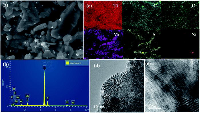 | ||
| Fig. 5 The surface morphology and elemental distribution of the NAMA-2 catalyst: SEM image (a), EDS spectrum (b), and elemental mapping (c). HRTEM images of AMA-2 (d) and NAMA-2 (e). | ||
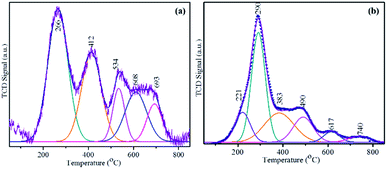
The H2-consumption of the prepared MoS2-based catalysts at a range of temperatures was obtained by temperature-programmed reduction (TPR) (Fig. 6). The heterostructured MoS2/Ti3C2Tx (AMA-2) or NiMoS2/Ti3C2Tx (NAMA-2) was placed in a quartz cell and pretreated at 150 °C in an Ar environment. A reducing gas containing 10% H2 in Ar was introduced into the sample quartz tube at a constant flow rate over the pretreated catalyst with a constant heating ramp of 10 °C min−1 up to 800 °C. The reduction of MoS2 on the Ti3C2Tx support was recorded based on H2 consumption signals by a thermal conductivity detector. The reduction peaks of labile sulfur moieties on the surface of the MoS2 supported catalysts (AMA and NAMA) were observed between around 200–800 °C. The AMA-2 signals were deconvoluted to five peaks located at 266, 412, 537, 608, and 693 °C, indicating sulfur dimers in the MoS2 layers. The edge sulfur atoms connected either with one or two Mo atoms, corresponding to hydrogen consumption signals at 266 and 412 °C, and another sulfur atom strongly bonded with Mo was evident in the range of 500–700 °C. The reduction of the NAMA-2 catalyst showed lower temperature peaks at 221, 290, 383, 490, and 617 °C, and Mo deeply intercalated in the support was reduced at 740 °C. The appearance of these reduction peaks at lower temperatures for the NAMA catalyst could be ascribed to the different reduction states of Mo due to the promoter Ni2+ placed next to Mo4+ edge ions and coordinated with S2− ions, which reduced the strong interaction of Mo with the support;46 this was also confirmed by XPS data (Fig. 4). The H2-TPR profiles of AMA and NAMA in the low-temperature region between around 250–300 °C indicated reduction either by excess sulfur, or by sulfur weakly bonded to the support surface.
Furthermore, the weakly attached sulfur atoms easily consumed H2 on the surface of MoS2 to form H2S, in a continuous process. Hence, these processes generated sulfur vacancies in the transition sulfide, in turn, enhancing catalytic activity. Also, as supported by DFT theory,47 physisorbed H2 could split into separate atoms that adsorbed on adjacent sulfur dimers present in the catalyst, forming two adjacent S–Mo–SH surface groups. Then, an H atom was transferred from one S–Mo–SH to form SH–Mo–SH groups. The chemisorbed sulfur led to the desorption of H2S and the other sulfur atom associated with the same Mo edge. Thus, the NAMA-2 catalyst TPR curve indicated different reduction states: Mo6+ to Mo4+, Mo4+ to Mo0, and Ni2+ to Ni0.48
Hydrodesulfurization activity on the MoS2/Ti3C2Tx and NiMoS2/Ti3C2Tx catalysts
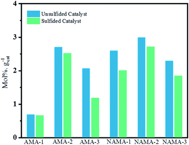
The few-layered MoS2 decorated on Ti3C2Tx was formulated with or without promoter (Ni) by impregnation with aqueous ATM alone, or with ATM and then the nickel salt, and subsequent calcination in an inert medium. The Mo loading varied, with samples prepared at 6, 9, and 12 wt% on Ti3C2Tx. These were denoted AMA-1, AMA-2, and AMA-3, respectively in the absence of promoter. The NiMoS2/Ti3C2Tx catalysts were intercalated by dispersion of promoter in ATM/Ti3C2Tx before calcination, with molar ratios of Ni/(Ni + Mo) of 0.39, 0.30, and 0.24 for the 6, 9, and 12 wt% Mo loadings, denoted NAMA-1, NAMA-2, and NAMA-3, respectively. The sulfur removal activity of each catalyst was investigated by using thiophene. Also, the above-mentioned catalysts were sulfided using H2S (to give S-AMA and S-NAMA), and their HDS activities were compared with those of the parent catalysts (AMA and NAMA). Typically, HDS activity was studied by passing saturated thiophene vapor over a catalyst loaded in a fixed-bed reactor, and the flow of thiophene concentration was controlled through a saturator system maintained at 5 °C. The amount of thiophene vapor from the saturator was calculated as 3.75 mol% using the Antoine eqn (1). The reaction was carried out at 350 °C, and the reactor outlet was connected to an online refinery gas analyzer for quantifying the desulfurized products and unreacted thiophene.31 The thiophene HDS reaction over AMA and NAMA catalysts showed the formation of significant amounts of C4 hydrocarbons (butane and butenes) and considerable amounts of C1–C3 hydrocarbons.The HDS of thiophene was carried out in triplicate over the AMA and NAMA catalysts and the rate of thiophene conversion was determined by taking the average value for each catalyst. Fig. 7 shows the HDS rates of the AMA-1, AMA-2, and AMA-3 catalysts, which were 1.2, 2.27, and 1.9 mmol h−1 g−1, respectively, while the conversion rates of the Ni-based NAMA-1, NAMA-2, and NAMA-3 catalysts were 3.5, 4.3, and 3.6 mmol h−1 g−1, respectively. It has previously been reported that traditional Ni–MoS2/Al2O3 exhibited HDS activity of about 2.5 mmol h−1 g−1.49 Thus, in comparison with the reported alumina catalysts, Ni–MoS2 on Ti3C2Tx showed higher HDS rates, which might be due to the synergistic effect of the 2D MoS2 in 2D Ti3C2Tx with the Ni promoter. Fig. 7 reveals that the HDS rates of the AMA and NAMA catalysts increased with increasing Mo loading up to 9 wt%, but upon a further increase in Mo loading, the activity decreased, which might be due to the nature of MoS2 intercalated between the MXene layers. The 9 wt% Mo showed higher conversion rates compared to the other two concentrations, which might be due to the metal–support Ti3C2Tx interactions, which also play a substantial role in the conversion rates; even when the Mo concentration was increased from 6 to 12% wt, a maximum conversion rate cut-off was achieved at 9 wt% Mo.50 However, the NAMA catalysts showed higher conversion rates than the AMA catalysts due to the synergic effect between the Ni particles sited at the surface of the S-layers, and the layer edges of active MoS2 sites which dominated on the surface of C–Ti–O. Further, the Raman spectra results illustrate that the frequency difference between theE12g and A1g modes in NAMA-3 was nearly 23 cm−1; the increase in the frequency difference could be attributed to the formation of close-packed multilayered MoS2. Thus, the formation of close-packed multilayered MoS2 with higher Mo loading might result in the lower catalytic activity of AMA-3, and NAMA-3.
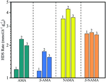 | ||
| Fig. 7 The comparison of the HDS activity of AMA and NAMA catalysts, and the conventional H2S-treated AMA and NAMA catalysts. | ||
In addition, the HDS of thiophene was investigated with H2S/H2-treated S-AMA and S-NAMA catalysts. The AMA and NAMA catalysts exhibited about 20% higher catalytic activities than the H2S/H2-treated S-AMA and S-NAMA catalysts. When compared with a similar study of H2S-treated Co–MoS2/alumina catalysts derived from ATM,51 the activity of NAMA-2 was about 7-fold higher than that of the H2S-treated Co–MoS2/alumina catalysts, due to the synergistic effect of Ni and MoS2 between the Ti3C2Tx slabs. Nevertheless, the decrease in HDS activity for the H2S/H2-treated S-AMA and S-NAMA catalysts might be due to inhibition of edge active MoS2.
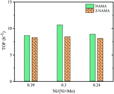
The turnover frequency (TOF) for the HDS of thiophene on Ni–MoS2/MXene was calculated from the ratio between the HDS activity of each NAMA catalyst (mol g−1 h−1) and the amount of Ni present in that NAMA catalyst (mol g−1).52 Fig. 8 shows the TOF as a function of the Ni/(Ni + Mo) ratio for the NAMA and S-NAMA catalysts. The highest TOF value was achieved with a Ni/(Ni + Mo) ratio of 0.30 (NAMA-2) which exceeded the values for NAMA-3 (low Ni content) and NAMA-1 (high Ni content). This confirmed that NAMA-2 was more intrinsically active compared to NAMA-1 and NAMA-3 due to the sintering of the active phase.
A number of products were obtained through the HDS of thiophene that were formed through various intermediates by hydrogenation of unsaturated carbon bonds and direct S removal from C–S bonds.47 The MoS2-based catalysts undergo parallel HDS reactions: the hydrogenation (C![[double bond, length as m-dash]](https://www.rsc.org/images/entities/char_e001.gif) C bond) involves the π-electrons of the S-ring compound adsorbed on the MoS2 layer, and direct S-removal (C–S bond) involves the exposed Mo ion and S vacancy site of chemisorbed S-atoms of thiophene via hydrogen transfer followed by sulfur elimination. These pathways involve different intermediates (dihydrothiophene, tetrahydrothiophene, and butadiene) and generate different products such as butenes (1-butene, cis-2-butene, trans-2-butene), butanes (n-butane, i-butane), and C1–C3 hydrocarbons (methane, ethane, ethene, propane, propene).50 The activities of the AMA and NAMA catalysts depended on the weakly bonded sulfur at the surface of the few-layered MoS2 for the generation of H2S, which created sulfur vacancies that reduced the energy barrier and favored the hydrogenation reaction, enhancing the catalytic conversion rates.
C bond) involves the π-electrons of the S-ring compound adsorbed on the MoS2 layer, and direct S-removal (C–S bond) involves the exposed Mo ion and S vacancy site of chemisorbed S-atoms of thiophene via hydrogen transfer followed by sulfur elimination. These pathways involve different intermediates (dihydrothiophene, tetrahydrothiophene, and butadiene) and generate different products such as butenes (1-butene, cis-2-butene, trans-2-butene), butanes (n-butane, i-butane), and C1–C3 hydrocarbons (methane, ethane, ethene, propane, propene).50 The activities of the AMA and NAMA catalysts depended on the weakly bonded sulfur at the surface of the few-layered MoS2 for the generation of H2S, which created sulfur vacancies that reduced the energy barrier and favored the hydrogenation reaction, enhancing the catalytic conversion rates.
Fig. 9 shows the average thiophene conversion by the synthesized (AMA and NAMA) and sulfided (S-AMA and S-NAMA) catalysts in terms of mol% per gram of catalyst at a particular time (5 h). The synthesized few-layered MoS2/Ti3C2Tx catalysts revealed higher conversion than the H2S-sulfided catalysts because of the saturation of the active sites with surface carbon. The AMA catalysts displayed an appreciable thiophene conversion due to the presence of corner MoS2 that helped to cleave C–S bonds, and edge MoS2 that enabled hydrogenation of thiophene.7,53 However, the Ni-promoted NAMA catalysts were more active for the dissociation of hydrogen molecules and their association with the evenly dispersed MoS2 on the support which strengthened the MoS2 hydrogen capacity. Furthermore, MoS2 peaks were not noticed in the XRD patterns of the NAMA catalysts, which suggests that the nanocrystalline MoS2 and Ni were highly dispersed to form Ni–Mo–S structures. In other words, the thermal conversion of intercalated ATM and promoter precursor on Ti3C2Tx in an inert medium favored the formation of an active Ni–Mo–S phase, and in turn, this decreased the formation of NiSx and NiOx, as confirmed by the XPS spectra. Thus, it is clear that the formation of the active Ni–Mo–S phase in the NAMA catalysts favored the high conversion of thiophene.
Fig. 10 shows the product distributions obtained on the AMA and NAMA catalysts and the corresponding sulfided catalysts (S-AMA and S-NAMA). The results reveal a declining trend in the formation of butenes and increasing proportion of butanes upon increasing Mo loading on the AMA catalysts, which favors the hydrogenation of thiophene; the conversion of low carbon products (C1–C3) remained the same at about 3–5% after completion of the HDS reaction. However, this change was not observed on the S-AMA catalysts due to the hidden edge MoS2 sites and so the distribution of butenes, butanes, and C1–C3 hydrocarbons corresponded to about ∼92%, ∼4%, and ∼4%, respectively. On the other hand, the NAMA and S-NAMA catalysts favored butenes (∼95% formation), while the formation of butanes and C1–C3 hydrocarbons slightly diminished over S-NAMA compared to those on NAMA catalysts. The sulfidation process might convert the active Ni promoter to inactive NiSx on the surface of the S-NAMA catalysts, which could decrease the hydrogenation of thiophene, resulting in the lower C1–C3 and butane contents.6,7 Overall, it was observed that the NAMA catalysts gave about 98% of C4 (butenes and butanes) and about 2% of C1–C3 hydrocarbons. Thus, the aqueous ATM and 2D MXene (titanium carbide) offer a new opportunity for the formulation of a new generation of catalysts. Moreover, using ATM as the Mo precursor provides a better in situ approach than a conventional hazardous H2S sulfidation process.
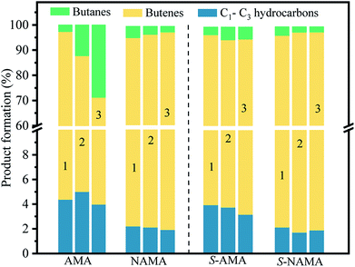 | ||
| Fig. 10 The distribution of HDS products on the parent AMA and NAMA catalysts, and the sulfided S-AMA, and S-NAMA catalysts. | ||
Conclusions
Few-layered MoS2 with and without Ni-promoted Ti3C2Tx (AMA and NAMA) catalysts were successfully prepared from the precursor ATM ((NH4)2MoS4) which was obtained in aqueous form by purging H2S through ammonium heptamolybdate. The AMA and NAMA catalysts were sulfided using H2S, to produce S-AMA and S-NAMA catalysts. The absence of MoS2 peaks in the XRD patterns of the AMA catalysts indicated the formation of highly dispersed nanocrystalline MoS2 on Ti3C2Tx. The intercalation of MoS2 and promoter between the layers of Ti3C2Tx and the number of MoS2 layers formed were confirmed from the textural properties of the catalysts and the active A1g and E12g Raman spectroscopy modes. HRTEM images and scanning electron microscopy coupled with energy dispersive X-ray spectroscopy (SEM-EDS) mapping revealed the catalyst surface morphology and elemental distribution. The electronic states of the elements on the surface of Ti3C2Tx that catalyzed the thiophene HDS were established by XPS analysis. The kinetic parameters were established from the conversion rates, and the formation of C1–C3, and C4 hydrocarbon products was quantified with GC. The overall reaction rate for HDS was higher for the NAMA than for the AMA catalysts due to the enhancement in rate provided by the promoter Ni. Furthermore, the prepared AMA and NAMA catalysts showed higher HDS rates than the corresponding sulfided catalysts because the H2S-sulfidation led to the poisoning of active MoS2 sites. The product distribution showed higher C4 (butane and butene) formation than C1–C3 product formation on the layered MoS2-MXene catalysts. The NAMA-2 catalyst with the 0.30 molar ratio of Ni/(Ni + Mo) exhibited the highest HDS rate and showed significant selectivity for n-butane and butenes. XRD and XPS data indicated that the active Ni–Mo–S structure formed on Ti3C2Tx for thiophene HDS through the hydrogenation and hydrogenolysis of C–S bonds. In summary, the epitaxial synthesis of HDS catalysts from ATM and 2D MXene provides an alternative route to conventional metal oxide sulfidation by H2S. Thus, the Ni-promoted few-layered MoS2/Ti3C2Tx catalyst is a potential candidate for achieving an enhanced HDS rate in the clean fuel process.Conflicts of interest
There are no conflicts to declare.Acknowledgements
This work was supported through the Petroleum Research Center funded by the Kuwait Institute for Scientific Research (KISR).References
- E. B. Fox, Z. W. Liu and Z. T. Liu, Energy Fuels, 2013, 27, 6335–6338 CrossRef CAS.
- P. Sikarwar, V. Gosu and V. Subbaramaiah, Rev. Chem. Eng., 2019, 35, 669–705 CAS.
- A. Stanislaus, A. Marafi and M. S. Rana, Catal. Today, 2010, 153, 1–68 CrossRef CAS.
- A. Tanimu and K. Alhooshani, Energy Fuels, 2019, 33, 2810–2838 CrossRef CAS.
- M. Breysse, P. Afanasiev, C. Geantet and M. Vrinat, Catal. Today, 2003, 86, 5–16 CrossRef CAS.
- E. Furimsky, Appl. Catal., A, 2003, 240, 1–28 CrossRef CAS.
- J. Jeon, Y. Park, S. Choi, J. Lee, S. S. Lim, B. H. Lee, Y. J. Song, J. H. Cho, Y. H. Jang and S. Lee, ACS Nano, 2018, 12, 338–346 CrossRef CAS PubMed.
- B. Hinnemann, J. K. Nørskov and H. Topsøe, J. Phys. Chem. B, 2005, 109, 2245–2253 CrossRef CAS PubMed.
- Y. Okamoto, Catal. Today, 1997, 39, 45–59 CrossRef CAS.
- R. R. Chianelli, G. Berhault and B. Torres, Catal. Today, 2009, 147, 275–286 CrossRef CAS.
- H. Topsøe, B. S. Clausen and F. E. Massoth, in Catalysis, Springer, 1996, pp. 1–269 Search PubMed.
- J. V. Lauritsen, S. Helveg, E. Laegsgaard, I. Stensgaard, B. S. Clausen, H. Topsoe and E. Besenbacher, J. Catal., 2001, 197, 1–5 CrossRef CAS.
- S. M. A. M. Bouwens, F. B. M. Vanzon, M. P. Vandijk, A. M. Vanderkraan, V. H. J. Debeer, J. A. R. Vanveen and D. C. Koningsberger, J. Catal., 1994, 146, 375–393 CrossRef CAS.
- A. I. Dugulan, J. A. R. van Veen and E. J. M. Hensen, Appl. Catal., B, 2013, 142, 178–186 CrossRef.
- Y. Aray and J. Rodriguez, J. Mol. Catal. A: Chem., 2007, 265, 32–41 CrossRef CAS.
- G. Alonso, G. Berhault and R. R. Chianelli, Inorg. Chim. Acta, 2001, 316, 105–109 CrossRef CAS.
- K. K. Liu, W. J. Zhang, Y. H. Lee, Y. C. Lin, M. T. Chang, C. Su, C. S. Chang, H. Li, Y. M. Shi, H. Zhang, C. S. Lai and L. J. Li, Nano Lett., 2012, 12, 1538–1544 CrossRef CAS PubMed.
- M. A. Al-Daous, Catal. Commun., 2015, 72, 180–184 CrossRef CAS.
- L. Yang, X. Z. Wang, Y. Liu, Z. F. Yu, J. J. Liang, B. B. Chen, C. Shi, S. Tian, X. Li and J. S. Qiu, Appl. Catal., B, 2017, 200, 211–221 CrossRef CAS.
- E. Puello-Polo, M. Ayala-G and J. L. Brito, Catal. Commun., 2014, 53, 9–14 CrossRef CAS.
- R. B. Levy and M. Boudart, Science, 1973, 181, 547–549 CrossRef CAS PubMed.
- R. V. Mom, J. N. Louwen, J. W. M. Frenken and I. M. N. Groot, Nat. Commun., 2019, 10, 2546 CrossRef PubMed.
- M. Naguib, V. N. Mochalin, M. W. Barsoum and Y. Gogotsi, Adv. Mater., 2014, 26, 992–1005 CrossRef CAS PubMed.
- B. Anasori, M. R. Lukatskaya and Y. Gogotsi, Nat. Rev. Mater., 2017, 2, 16098 CrossRef CAS.
- Y. Liu, H. Du, X. Zhang, Y. Yang, M. Gao and H. Pan, Chem. Commun., 2016, 52, 705–708 RSC.
- N. Li, X. Z. Chen, W. J. Ong, D. R. MacFarlane, X. J. Zhao, A. K. Cheetham and C. H. Sun, ACS Nano, 2017, 11, 10825–10833 CrossRef CAS PubMed.
- H. Liu, C. Y. Duan, C. H. Yang, W. Q. Shen, F. Wang and Z. F. Zhu, Sens. Actuators, B, 2015, 218, 60–66 CrossRef CAS.
- Y. L. Ying, Y. Liu, X. Y. Wang, Y. Y. Mao, W. Cao, P. Hu and X. S. Peng, ACS Appl. Mater. Interfaces, 2015, 7, 1795–1803 CrossRef CAS PubMed.
- L. Ding, Y. Y. Wei, L. B. Li, T. Zhang, H. H. Wang, J. Xue, L. X. Ding, S. Q. Wang, J. Caro and Y. Gogotsi, Nat. Commun., 2018, 9, 155 CrossRef PubMed.
- M. Alhabeb, K. Maleski, B. Anasori, P. Lelyukh, L. Clark, S. Sin and Y. Gogotsi, Chem. Mater., 2017, 29, 7633–7644 CrossRef CAS.
- M. Vinoba, R. Navvamani and H. Al-Sheeha, SN Appl. Sci., 2019, 1, 340 CrossRef.
- P. Rayo, A. Rodriguez-Hernandez, P. Torres-Mancera, J. A. D. Munoz, J. Ancheyta and R. G. de Leon, Catal. Today, 2018, 305, 2–12 CrossRef CAS.
- B. S. Guo, J. Bai, Y. H. Li, S. Q. Xia and P. S. Ma, Fluid Phase Equilib., 2013, 353, 87–92 CrossRef CAS.
- M. Naguib, M. Kurtoglu, V. Presser, J. Lu, J. J. Niu, M. Heon, L. Hultman, Y. Gogotsi and M. W. Barsoum, Adv. Mater., 2011, 23, 4248–4253 CrossRef CAS PubMed.
- N. V. Tzenov and M. W. Barsoum, J. Am. Ceram. Soc., 2000, 83, 825–832 CrossRef CAS.
- J. F. Zhu, Y. Tang, C. H. Yang, F. Wang and M. J. Cao, J. Electrochem. Soc., 2016, 163, A785–A791 CrossRef CAS.
- B. Schönfeld, J. J. Huang and S. C. Moss, Acta Crystallogr., Sect. B: Struct. Sci., 1983, 39, 404–407 CrossRef.
- N. H. Attanayake, S. C. Abeyweera, A. C. Thenuwara, B. Anasori, Y. Gogotsi, Y. G. Sun and D. R. Strongin, J. Mater. Chem. A, 2018, 6, 16882–16889 RSC.
- J. Kibsgaard, Z. B. Chen, B. N. Reinecke and T. F. Jaramillo, Nat. Mater., 2012, 11, 963–969 CrossRef CAS PubMed.
- C. Lee, H. Yan, L. E. Brus, T. F. Heinz, J. Hone and S. Ryu, ACS Nano, 2010, 4, 2695–2700 CrossRef CAS PubMed.
- J. P. Liu, Y. Z. Liu, D. Y. Xu, Y. Z. Zhu, W. C. Peng, Y. Li, F. B. Zhang and X. B. Fan, Appl. Catal., B, 2019, 241, 89–94 CrossRef CAS.
- C. J. Shen, L. B. Wang, A. G. Zhou, H. Zhang, Z. H. Chen, Q. K. Hu and G. Qin, J. Electrochem. Soc., 2017, 164, A2654–A2659 CrossRef CAS.
- N. X. Hao, Y. Wei, J. L. Wang, Z. W. Wang, Z. H. Zhu, S. L. Zhao, M. Han and X. Huang, RSC Adv., 2018, 8, 20576–20584 RSC.
- A. López-Benítez, A. Guevara-Lara and G. Berhault, ACS Catal., 2019, 9, 6711–6727 CrossRef.
- J. Liang, M. Wu, P. Wei, J. Zhao, H. Huang, C. Li, Y. Lu, Y. Liu and C. Liu, J. Catal., 2018, 358, 155–167 CrossRef CAS.
- P. Castillo-Villalon, J. Ramirez and J. A. Vargas-Luciano, J. Catal., 2014, 320, 127–136 CrossRef CAS.
- C. Guo, T. Zhang, M. Niu, S. F. Cao, S. X. Wei, Z. J. Wang, W. Y. Guo, X. Q. Lu and C. M. L. Wu, Mol. Catal., 2019, 463, 67–76 CrossRef CAS.
- W. K. Lai, W. J. Song, L. Q. Pang, Z. F. Wu, N. Zheng, J. J. Li, J. B. Zheng, X. D. Yi and W. P. Fang, J. Catal., 2013, 303, 80–91 CrossRef CAS.
- Y. Okamoto, K. Ochiai, M. Kawano and T. Kubota, J. Catal., 2004, 222, 143–151 CrossRef CAS.
- M. J. Girgis and B. C. Gates, Ind. Eng. Chem. Res., 1991, 30, 2021–2058 CrossRef CAS.
- A. Nogueira, R. Znaiguia, D. Uzio, P. Afanasiev and G. Berhault, Appl. Catal., A, 2012, 429–430, 92–105 CrossRef CAS.
- Y. Okamoto, A. Kato, Usman, N. Rinaldi, T. Fujikawa, H. Koshika, I. Hiromitsu and T. Kubota, J. Catal., 2009, 265, 216–228 CrossRef CAS.
- G. Berhault, A. Mehta, A. C. Pavel, J. Yang, L. Rendon, M. J. Yácaman, L. C. Araiza, A. D. Moller and R. R. Chianelli, J. Catal., 2001, 198, 9–19 CrossRef CAS.
Footnote |
| † Electronic supplementary information (ESI) available: Details of the materials and their characterization; XRD patterns for MAX, MXene and catalysts; and BET characterization of catalysts. See DOI: 10.1039/d0ra01158d |
| This journal is © The Royal Society of Chemistry 2020 |

