 Open Access Article
A visible-light-responsive TaON/CdS photocatalytic film with a ZnS passivation layer for highly extraordinary NO2 photodegradation†
Dandan Yan‡
,
Tingting Wei‡,
Wencheng Fang,
Zhanbin Jin,
Fengyan Li *,
Zhinan Xia and
Lin Xu
 *
*
Key Laboratory of Polyoxometalate Science of Ministry of Education, Department of Chemistry, Northeast Normal University, Changchun, Jilin 130024, P. R. China. E-mail: lify525@nenu.edu.cn; linxu@nenu.edu.cn; Fax: +86-0431-85099765; Tel: +86-0431-85098760
First published on 3rd September 2020
Abstract
Recently, TaON has become a promising photoelectrode material in the photocatalytic field owing to its suitable band gap and superior charge carrier transfer ability. In this work, we prepared a TaON/CdS photocatalytic film using a CdS nanoparticle-modified TaON film by the successive ionic layer adsorption and reaction (SILAR) method. For the first time, the ZnS nanoparticles were deposited on the TaON/CdS film using the same method. We found that pure TaON had a nanoporous morphology, thus resulting in high specific surface area and better gas adsorption capacity. Furthermore, the TaON/CdS/ZnS film displayed a highly efficient NO2 photodegradation rate under visible light irradiation owing to its stronger visible light response, photocorrosion preventive capacity, and the high separation efficiency of photo-induced electrons and holes. Interestingly, the promising TaON/CdS/ZnS film also possessed remarkable recyclability for NO2 degradation. Therefore, we suggest that the TaON/CdS/ZnS photocatalytic film might be used for the photocatalytic degradation of other pollutants or in other applications. We also put forward the feasible NO2 photocatalytic degradation mechanism for the TaON/CdS/ZnS film. From the schematic diagram, we could further obtain the photo-generated carrier transport process and NO2 photodegradation principle in detail over the ternary photocatalytic film. Moreover, the trapping experiment demonstrates that ·O2− and h+ all play significant roles in NO2 degradation under visible light irradiation.
Introduction
In recent years, NOx, attributed to the rapid development of urbanization and the popularity of vehicles, have become some of the key atmospheric pollutants, resulting in very rigorous environmental damage such as photochemical haze pollution and acid rain.1 NOx can lead to environmental pollution and respiratory diseases in humans, and also greatly facilitate the conversion of SO2 into sulfate, thus leading to the formation of severe haze.2 Particularly, as an irritating and highly toxic gas, NO2 can cause more serious harm to human health such as a decrease in immunity and the degradation of lung tissue, even at very low concentrations.3 Therefore, the effective elimination of NO2 is extremely necessary and important, which has also attracted a lot of attention. For example, all kinds of NO2 gas sensors, possessing the advantageous features of real-time monitoring, miniaturization, good recoverability and operating at room temperature, have been investigated in order to effectively detect NO2 and thus remove it.4,5 Until now, many different techniques have been developed for NO2 elimination, for example, the NO2 adsorption and reduction method over zeolite and activated carbon, the NO2 storage method and the catalytic removal technology of NO2 involving photocatalysis and selective catalytic reduction.6–8 Photocatalysis has become one of the most significant technologies for NO2 removal owing to the efficiency and the effective use of solar energy. And many semiconductor materials and their composite materials have served as photocatalysts, such as TiO2, acrylic-silicon/nano-TiO2 films, TiO2/rubber, concrete pavement containing TiO2, g-C3N4, SnO2 quantum dots anchored on g-C3N4, Mn3O4/γ-Al2O3, etc.9–19 However, because these photocatalysts present relatively low NO2 degradation rates or poor stability, exploring better photocatalytic materials for NO2 degradation has become necessary and meaningful.In the past few years, TaON has gradually become one of the most promising and highly regarded photocatalytic materials due to its suitable bandgap (about 2.5 eV) and positions of the valence band and conduction band, and its environmentally friendly features.20,21 Being yellow, yellow-green and orange-yellow in color, TaON can absorb visible light, thus turning into a relatively new and interesting photocatalyst.22,23 As such, TaON used to be a quite important and popular photocatalyst for solar water splitting (water splitting into H2 and O2).24–28 Nevertheless, further extensive applications of pure TaON material are limited, to some extent benefiting from its recombination losses of photogenerated electron and hole pairs, self-oxidative deactivation, low carrier mobility and poor stability.29,30 The construction of heterogeneous materials could well facilitate electron transportation and charge separation, thus improving the photoelectrochemical performance, e.g., SnO2/SnS2, SnO2/C, MoS2/C, etc., as previously reported.31–33 Accordingly, some researchers have worked out some composite materials and heterojunctions of TaON to overcome these drawbacks to further modify and enhance the photocatalytic performance.34–36 Recently, apart from the photocatalytic decomposition of water, the TaON material family has also been used for the photocatalytic degradation of pollutants and has served as the counter electrode for dye-sensitized solar cells.37,38 To date, using TaON photocatalysts to eliminate NO2 has not been investigated and we have found that TaON could be a good photocatalyst for NO2 photodegradation due to its nanoporous morphology and effective response to visible light.
Plenty of other semiconductors have been used to modify TaON material in order to further strengthen its photoelectrochemical performance. Among them, CdS, possessing a relatively narrow bandgap (approximately 2.4 eV) and a more negative conduction band position leading to its excellent responsiveness to visible light, is one of the most attractive photocatalytic materials.39,40 Various methods, such as chemical bath deposition (CBD), successive ionic layer adsorption and reaction (SILAR) and electrochemical deposition have been investigated to assemble CdS on some semiconductor material film.41–44 Unfortunately, the photocatalysts modified by only CdS hardly presented enhanced photocatalytic activity, which is because CdS is prone to photo-corrosion during photocatalysis, in other words, because S2− is easily oxidized by photo-induced holes.45 Therefore, some useful strategies have been explored to overcome this fatal disadvantage of CdS. Building heterostructures and loading co-catalysts are the widely adopted strategies.46 Employing ZnS as the passivation layer to effectively prevent the photo-corrosion of CdS is the broadest and most effective method. For instance, structures like CdS/ZnS nanoparticle composites, CdS–ZnS core–shell structures and core/shell CdSe/ZnS QDs, etc. have been established to achieve enhanced photostability and photocatalytic ability.47–51 Zhu's group prepared CdS@TaON core–shell composites coupled with graphene oxide nanosheets and Hou's group fabricated MoS2–CdS–TaON hollow composites, which have all achieved efficient photocatalytic hydrogen production.52,53 Zhang's group synthesized ZnS–CdS–TaON nanocomposites through a modified sol–gel method for photocatalytic hydrogen evolution.54 However, the preparation methods of TaON and ZnS–CdS–TaON are cumbersome and result in different morphologies and different photocatalytic properties.
Here, we have successfully prepared such photocatalytic films containing pure TaON, TaON/CdS and TaON/CdS/ZnS films through simple and effective methods (successive ionic layer adsorption and reaction (SILAR) method) to study their photoelectrochemical performances. We have carried out a series of experiments on the photocatalytic degradation of NO2 under visible light irradiation to check the photocatalytic capacities of these fabricated films. We found that photoelectrochemical tests, as well as NO2 degradation measurements, confirmed that TaON/CdS with the ZnS passivation layer exhibited the best charge carrier separation rate, most outstanding photocatalytic activity and excellent stability for NO2 photodegradation. The TaON/CdS/ZnS film exhibited remarkably increased NO2 degradation efficiency as compared to the pure TaON film, which achieved 96.7% in 2 h. Finally, we designed a schematic diagram of possible photocatalytic degradation mechanisms to investigate, in-depth, the reasons for the significant improvement in the photocatalytic performance of the TaON/CdS/ZnS photocatalytic film. The trapping experiment over TaON/CdS/ZnS film was conducted to further study the main active species in NO2 photodegradation.
Experimental
Preparation of TaON films
TaON powder was synthesized as previously reported.55 Typically, 2.0 g of Ta2O5 powder was evenly placed in a porcelain boat and heated at 850 °C for 8 h under flowing ammonia (the ammonia flow rate: 120 mL min−1), and then the TaON films were prepared by the doctor-blade method. TaON, ethylcellulose was mixed with terpineol in the ratio of 1![[thin space (1/6-em)]](https://www.rsc.org/images/entities/char_2009.gif) :
:![[thin space (1/6-em)]](https://www.rsc.org/images/entities/char_2009.gif) 0.5
0.5![[thin space (1/6-em)]](https://www.rsc.org/images/entities/char_2009.gif) :
:![[thin space (1/6-em)]](https://www.rsc.org/images/entities/char_2009.gif) 4 and an appropriate amount of ethanol was also added in an agate mortar. These mixtures were ground for 30 min to become slurries at room temperature. Subsequently, the slurry was scraped onto the conductive surface of a clean FTO with a 1 cm2 effective area, followed by drying at 80 °C, first on a heating plate, and then annealing at 300 °C for 2 h in a muffle furnace to obtain the TaON films.
4 and an appropriate amount of ethanol was also added in an agate mortar. These mixtures were ground for 30 min to become slurries at room temperature. Subsequently, the slurry was scraped onto the conductive surface of a clean FTO with a 1 cm2 effective area, followed by drying at 80 °C, first on a heating plate, and then annealing at 300 °C for 2 h in a muffle furnace to obtain the TaON films.
The deposition of CdS on TaON films
CdS was deposited on the TaON films through the successive ionic layer adsorption and reaction (SILAR) method. Briefly, the TaON film was first immersed in a 0.05 M Cd(NO3)2 aqueous solution for 2 min, followed by rinsing with DI water. Afterwards, the TaON film was dipped into 0.05 M Na2S aqueous solution for 2 min, and then rinsed with DI water. This process is considered as one SILAR cycle. Finally, the TaON/CdS films were formed by duplicating 15 SILAR cycles and annealing at 200 °C for 2 h with a heating rate of 3 °C min−1 in a muffle furnace.The deposition of CdS and ZnS on TaON films
The synthesis method for TaON/CdS/ZnS films is similar to the preparation of TaON/CdS films. Therefore, the TaON/CdS film was dipped into 0.05 M Zn(CH3COO)2 aqueous solution for 2 min, followed by treating with 0.05 M Na2S aqueous solution for 2 min; the film was rinsed with DI water after each soak. On repeating 35 cycles, the film was dried at 100 °C for 1 h on the heating plate to give the TaON/CdS/ZnS film.Characterization of the films
The crystallography of the films was studied by X-ray diffraction (XRD) (D/Max200PC Diffractometer with CuKα1 radiation over a 2θ range from 5° to 80°; the accelerating voltage and applied current were 40 kV and 30 mA, respectively). The film morphology and elemental composition were determined with SEM/EDX (Hitachi SU-800 FE-SEM). For a detailed internal structure, transmission electron microscopy (TEM) and high-resolution transmission electron microscopy (HRTEM) were studied using a JEM-2100F microscope. The determination of the absorbance intensity and the band gaps of the films were measured using UV-vis diffuse reflectance spectra (DRS) (Varian Cary 50 UV-vis spectrophotometer). The oxidation state information of the films was measured by X-ray photoelectron spectroscopy (XPS) (USWHA150 photoelectron spectrometer with Al Kα radiation). Measurements of the photocatalytic performance of the films were determined by photoluminescence (PL) spectra (F-7000 fluorescence spectrophotometer).Photoelectrochemical assessment
Several measurements including amperometry (i–t), electrochemical impedance spectroscopy (EIS) and linear sweep voltammetry (LSV) were performed to check the photoelectrochemical activity of all prepared films. All experiments were carried out on an IVIUM Electrochemical Workstation (Tianjin Brillante Technology Limited) at room temperature. The I-t measurements were taken at the constant bias of 0.3 V. The EIS tests were performed in a frequency range from 0.1 Hz to 1000 kHz at −0.2 V under visible light irradiation. The LSV plots of H2O2 oxidation were investigated in the range of 0.2–2.0 V in 0.5 M Na2SO4 aqueous solution mixed with 5 mM H2O2. All of the tests were conducted in a quartz beaker with a standard three-electrode system, in which the 0.5 M Na2SO4 aqueous solution was made to be the electrolyte, the Ag/AgCl electrode was the reference electrode, a Pt wire served as the counter electrode and the prepared films were used as working electrodes. A 300 W Xe lamp (PLS-SXE300C) coupled with the constant integrated irradiance value (100 mW cm−2) in the wavelength range (λ > 420 nm) was made to be the irradiation source and the effective irradiation area (1.0 × 1.0 cm2) of all films was fixed throughout all measurements.Photocatalytic activity assessment
The assessment of the photocatalytic activity of all the prepared films was conducted via NO2 photodegradation measurement. NO2 is a common gas pollutant whose concentration is determined by a standard method and the approach adopted extensively is called the Saltzman method. NO2 can be absorbed by the absorption liquid and reacts to form a pink azo dye that has an absorbance peak at 540 nm. The absorption liquid was made up of 1 mL DI water and 4 mL color-substrate solution. The color-substrate solution was prepared using the following method: 500 mL of an aqueous solution containing 5 g p-aminobenzenesulfonic acid and 50 mL glacial acetic acid mixed with 50 mL of 1 g L−1 naphthalene ethylenediamine aqueous solution were poured into a 1000 mL volumetric flask. The absorbance is proportional to the NO2 concentration and thus, the rate at which the peak height was reduced during the measurement served as a measure of the photodegradation rate of the NO2 in contact with the photocatalytic films. The tests of photocatalytic activity were conducted using a visible light source with a 300 W Xe lamp and the photocurrent density was 100 mW cm−2. The effective area of irradiation was 1 cm2 for all photocatalytic films.The simple schematic diagram for the NO2 photodegradation system exhibited in Fig. S1† enables us to understand the photocatalytic degradation process. About 800 ppb of NO2 was first infused into a 500 mL quartz reaction vessel containing the photocatalytic films, and the system was kept in the dark for 30 min at room temperature to reach the adsorption–desorption equilibrium. Afterwards, 2.5 mL of gas was sucked from the system and transfused into the absorption liquid, and the absorbance served as the initial concentration (C0). The vessel was then irradiated with visible light for 0.5 h, 1 h, 1.5 h and 2 h, respectively. After irradiation, 2.5 mL gas was taken out and injected into the absorption liquid and the absorbance was used as the final concentration (C). Therefore, (C0 − C)/C0 ×100% was used to calculate the NO2 degradation efficiency.
The cycling experiment of NO2 photodegradation over TaON/CdS/ZnS film was conducted as follows. The ternary composite film was first used for NO2 photodegradation with visible light illumination for 2 h. The film was kept in air for 1 h and then used to again photocatalytically degrade NO2 for 2 h. This procedure was repeated 4 times to determine the recyclability and stability of the TaON/CdS/ZnS photocatalytic film.
Trapping experiment
The trapping experiment was conducted by spin-coating the capturing agent of the active species on the TaON/CdS/ZnS photocatalytic film then photodegrading NO2. In detail, 100 μL of a 6 mmol mL−1 scavenger aqueous solution was dropped onto the TaON/CdS/ZnS film and spin-coated for 30 s at a predetermined speed, which was repeated three times and the film was dried at room temperature. Finally, the TaON/CdS/ZnS photocatalytic film coated with the trapping reagent served to remove NO2 under visible light illumination.Results and discussion
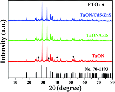
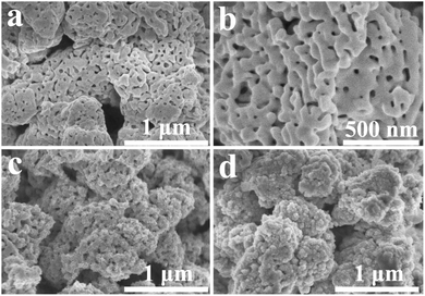
The XRD analysis of TaON, TaON/CdS and TaON/CdS/ZnS films demonstrated the crystal structures and crystal phase. The patterns confirmed that the monoclinic-phase TaON films (JCPDS no. 70-1193)55 were successfully prepared apart from the diffraction peaks of the FTO substrate (Fig. 1). Strong peaks were observed at 29.1°, 32.7° and 35.1°, corresponding to the (−111), (111) and (002) diffraction planes of the monoclinic-phase TaON, respectively. The diffraction peaks of CdS and ZnS for TaON/CdS and TaON/CdS/ZnS films were hardly found, which was due to the very weak diffraction peaks relative to TaON and the successful co-incorporation of CdS and ZnS into TaON films.The SEM morphologies and photographs of TaON, TaON/CdS and TaON/CdS/ZnS films are shown in Fig. 2. The porous microspheres possess a relatively irregular particle profile with a large number of nanopores (Fig. 2a and b). The CdS particles were uniformly deposited on TaON films with plenty of nanopores (Fig. 2c). The nanopores were completely covered after depositing ZnS particles onto the TaON/CdS films (Fig. 2d). The uniform microspheres did not change with the deposition of CdS particles or CdS and ZnS particles. The EDX analyses of pure TaON, TaON/CdS and TaON/CdS/ZnS photocatalysts are exhibited in Fig. S2,† which fully illustrates the presence of all the elements they contained. Fig. S3† shows the corresponding EDX element mappings of TaON/CdS/ZnS films. It was found that all the elements containing Ta, O, N, Cd, Zn and S were distributed uniformly throughout the TaON/CdS/ZnS composite film, which powerfully confirmed the even co-deposition of CdS and ZnS on TaON films.
To further prove the structure of all films, the measurements of N2 adsorption–desorption isotherms and the corresponding PSD were conducted and displayed in Fig. S4.†
The films showed a type IV isotherm with a type H3 hysteresis loop, suggesting the presence of mesopores. Fig. S4† reveals that the BET surface area of TaON was 47.56 m2 g−1, which was bigger as compared to TaON/CdS (6.12 m2 g−1) and TaON/CdS/ZnS (4.93 m2 g−1). This result may be due to the deposition of CdS and ZnS. Table S1† shows that the pore sizes of all films were in the range of 2–50 nm, indicating the mesoporous structure, which resulted in enhanced harvesting of the visible light.56,57 Compared to pure TaON, TaON/CdS and TaON/CdS/ZnS films demonstrated a hierarchical porosity composed of macropores and mesopores, and this interesting porosity facilitated fast mass transport, thus resulting in improved photocatalytic activity.58–60
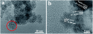
The purpose of TEM performance was to further determine the microstructure of the TaON/CdS/ZnS composite films. As shown in Fig. 3a, the TaON/CdS/ZnS film exhibited an inconspicuous particle profile with a rough surface and lots of small-sized of CdS and ZnS particles were homogeneously dispersed on the TaON surface. To further confirm the existence and the specific locations of CdS and ZnS particles in the composite film, HRTEM analysis was conducted which is illustrated in Fig. 3b. The region with an interplanar spacing of 0.273 nm is consistent with the (111) crystallographic plane of the monoclinic-phase TaON. This observation corresponds to the XRD results. At the interface of CdS and TaON, the HRTEM image showed a lattice fringe spacing of 0.336 nm in accordance with the (111) plane of CdS. The lattice spacing of 0.308 nm was assigned to the (111) plane of ZnS at the edge of the composite film.54 Therefore, the TEM and HRTEM analyses amply demonstrated the co-existence and the position of CdS and ZnS in the TaON/CdS/ZnS film.
Fig. 4 displays the UV-vis absorption spectra to better assess the light-harvesting abilities of the as-fabricated TaON, TaON/CdS and TaON/CdS/ZnS photocatalyst thin films. The characteristic absorption edge at the near-infrared area was observed for pure TaON, probably due to the orange-colored TaON powder, implying that the pure TaON film possesses the excellent ability to absorb visible light. This result was consistent with the charge transfer process from the valence band to the conduction band of the TaON photocatalyst film under visible light irradiation. For the TaON/CdS and TaON/CdS/ZnS films, although the absorption edges at around 650 nm demonstrated a blue shift, the light absorption intensity exhibited obvious enhancement at 400–540 nm as compared to the pure TaON. The TaON/CdS/ZnS film showed a more significant increase than TaON, fully exhibiting the stronger absorption capacity and more excellent photocatalytic activity after depositing CdS nanoparticles on the TaON film and with the ZnS-passivation layers at the same time.
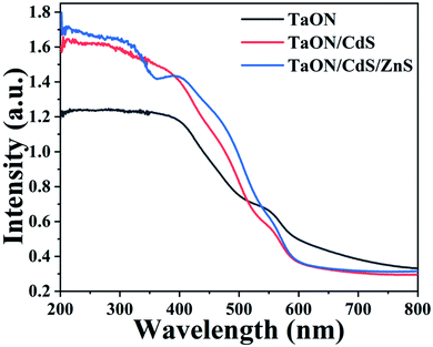 | ||
| Fig. 4 UV-vis absorption spectra of the as-prepared TaON, TaON/CdS and TaON/CdS/ZnS films, respectively. | ||
To verify the specific surface chemical constituents and elemental valencies of the as-synthesized TaON/CdS/ZnS photocatalyst film, XPS spectra were studied and the C (1s) peak at 284.8 eV served as the reference peak to calibrate the XPS spectra. From the XPS survey spectra in Fig. S5,† Ta, O, N, Cd, Zn and S elements were all detected in the prepared composite sample, corresponding to the chemical compositions of TaON/CdS/ZnS. In Fig. 5a, two peaks at 25.7 eV and 27.5 eV were attributed to 4f7/2 and Ta 4f5/2 signals, respectively, consistent with the +5-oxidation state of Ta.61 The binding energy of N 1s was 404.7 eV, indicating the existence of the −3-oxidation state of N (Fig. 5b). Fig. 5c presents the peak at 532.0 eV, assigned to the O 1s, which corresponds to O2−.54 The binding energies of 404.9 eV and 411.7 eV in Fig. 5d were ascribed to Cd 3d5/2 and Cd 3d3/2, which belonged to Cd2+. As shown in Fig. 5e, two symmetric peaks at 1021.6 eV and 1044.7 eV belong to Zn 2p1/2 and Zn 2p3/2, corresponding to the state mainly reported for divalent sulfides. In Fig. 5f, S 2p can be divided into two peaks 2p3/2 and 2p1/2, located at 160.1 eV and 161.5 eV, respectively. This result demonstrated that the Cd–S and Zn–S bonding existed in the TaON/CdS/ZnS photocatalytic film.46
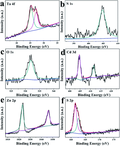 | ||
| Fig. 5 XPS spectra of (a) Ta 4f, (b) N 1s, (c) O 1s, (d) Cd 3d, (e) Zn 2p and (f) S 2p for the TaON/CdS/ZnS composite film. | ||
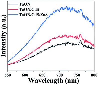
The transfer, separation and trapping of photogenerated charge carriers on the as-fabricated film surfaces were determined via photoluminescence spectroscopy (PL) and the typical photoexcitation wavelength was 400 nm, as exhibited in Fig. 6. TaON, TaON/CdS and TaON/CdS/ZnS films all displayed a luminescence band centered at 710 nm. The photoluminescence efficiencies of TaON/CdS and TaON/CdS/ZnS photocatalysts were both greater than the pure TaON film, especially the TaON/CdS/ZnS photocatalyst film. This may have resulted from the significant reduction in the density of the nonradiative transition recombination sites for photocatalytic composite films, particularly in TaON/CdS/ZnS. Furthermore, pure TaON could serve as effective capture traps for photogenerated carriers due to the reduced Ta species possessing a lower conduction band position than TaON. The low photoluminescence intensity of pure TaON was considered to reflect an increase in the prevalence of nonradiative transitions in the photocatalytic film. The identical trend in the photoluminescence and photocatalytic activity was reported in the TaON and TaON–ZrO2 photocatalysts. As a result, the pure TaON photocatalyst with low photoluminescence intensity exhibited reduced photocatalytic performance as compared to the composite photocatalyst films.62
To further verify the separation rates of the photogenerated electron and hole pairs, the transient photocurrents of the TaON, TaON/CdS and TaON/CdS/ZnS photocatalytic films were conducted under visible light irradiation. As displayed in Fig. 7a, all the films exhibited a quick response to the incident light on–off circulation: in particular, the TaON/CdS/ZnS composite photocatalysts showed greater enhancement in the transient photocurrent as compared to the pure TaON and TaON/CdS films. The improved photocurrent of the TaON/CdS/ZnS photocatalysts distinctly revealed the efficient photo-induced charge separation efficiency. Some spike peaks appeared in the I–t plots of the pure TaON and TaON/CdS photocatalytic films, which were attributed to the slower surface water oxidation reaction kinetics and faster recombination of photogenerated carriers for the TaON and TaON/CdS films. However, benefiting from the ZnS passivation, TaON/CdS/ZnS films presented remarkable photocurrent density along with a very stable photocurrent trend. Therefore, with the CdS nanoparticle deposition and ZnS passivation on TaON films, the TaON/CdS/ZnS films demonstrated the high efficiency of the photogenerated charge separation and transfer, thus leading to excellent photocatalytic capacities. Electrochemical Impedance Spectroscopy (EIS) was carried out to obtain deep insight into the photo-generated carrier transfer and separation performance and the synergistic effect of surface water oxidation kinetics for all photocatalyst films. Fig. 7b shows that TaON/CdS/ZnS films exhibited the smallest arc radius among the plots for all the films, consistent with the transient photocurrent measurements. Table 1 shows that the Rs values, as well as the Rct values of the TaON/CdS/ZnS film, were the smallest among all the photocatalytic films. These results fully illustrated that the TaON/CdS/ZnS photocatalytic films possessed the lowest resistance, thus promoting the efficient separation and transfer of photo-induced charge carriers and resulting in the enormous enhancement of the NO2 photodegradation efficiency.
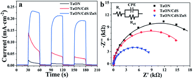 | ||
| Fig. 7 (a) Transient current plots (I–t) and (b) Nyquist plots of TaON, TaON/CdS and TaON/CdS/ZnS films under the irradiation of visible light. | ||
| Photocatalytic film | Rs (Ω) | Rct (Ω) |
|---|---|---|
| TaON | 71.5 | 21![[thin space (1/6-em)]](https://www.rsc.org/images/entities/char_2009.gif) 970 970 |
| TaON/CdS | 61.7 | 17![[thin space (1/6-em)]](https://www.rsc.org/images/entities/char_2009.gif) 650 650 |
| TaON/CdS/ZnS | 52.5 | 9706 |
It was found that the TaON/CdS/ZnS photocatalytic films displayed a higher photocurrent as compared to the pure TaON and TaON/CdS films, which represented the more efficient water oxidation reaction kinetics. The excellent photoelectrocatalytic activity was generally due to the restrained recombination of photo-generated electron and hole pairs. The recombination occurred not only on the surface but also in the bulk of all the films. It is well known that benefiting from the lower reduction potential and faster water oxidation kinetics, H2O2 could be easily oxidized to remove the photo-induced holes.63 Therefore, H2O2 served as the sacrificial reagent of holes in the LSV measurements to demonstrate the photogenerated carrier transfer process. As exhibited in Fig. 8, pure TaON, TaON/CdS and TaON/CdS/ZnS films all showed improved photocurrents with the addition of H2O2 to the Na2SO4 electrolyte. The pure TaON films presented a greater increase than TaON/CdS and TaON/CdS/ZnS films in the presence of H2O2, which distinctly disclosed that H2O2 greatly facilitated the injection of holes into the electrolyte and lightened the surface recombination of pure TaON films. However, TaON/CdS and TaON/CdS/ZnS films displayed relatively small improvements, especially the TaON/CdS/ZnS photocatalyst. This indicated that the TaON/CdS/ZnS composite films possessed the least surface recombination due to the simultaneous deposition of CdS and ZnS onto TaON films, thus leading to the remarkable photoelectrocatalytic performance.
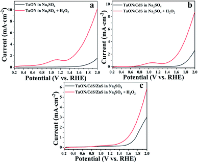 | ||
| Fig. 8 LSV plots of (a) pure TaON film, (b) TaON/CdS film and (c) TaON/CdS/ZnS film tested in 0.5 M Na2SO4 electrolyte in the presence or absence of H2O2 with the irradiation of visible light. | ||
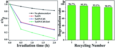
NO2 photocatalytic degradation experiments for all fabricated films aimed to further study the photocatalytic performance for the TaON film with the synergistic effects of CdS deposition and ZnS passivation. The NO2 photodegradation measurements were carried out under visible light irradiation and the effective area was 1 cm2 for all photocatalytic films. As exhibited in Fig. 9a, the concentration of NO2 showed a slight decrease without any photocatalyst after 2 h of visible light irradiation, which may be due to the equilibrium conversion between NO2 and other gases. Pure TaON film presented higher NO2 degradation efficiency reaching about 72.6% after only 2 h of light illumination. However, the NO2 photodegradation rate of the TaON/CdS film was barely improved, indicating the deposition of CdS nanoparticles on the TaON film. From this unusual phenomenon, it can be inferred that the slight enhancement of NO2 degradation for the TaON/CdS film may be due to the intense photo corrosion of CdS itself and the strong oxidizing property of NO2. Nevertheless, benefiting from the ZnS passivation layer at the outermost layer of TaON/CdS, the TaON/CdS/ZnS film exhibited remarkably increased NO2 degradation efficiency as compared to the pure TaON film, which achieved 96.7%. Therefore, this result leads us to conclude that ZnS passivation could greatly prevent the photo corrosion of CdS, thus resulting in the very beneficial photocatalytic performance of the TaON/CdS/ZnS film. The repeated NO2 photodegradation experiment was performed to further determine the recyclability and stability of the TaON/CdS/ZnS photocatalytic film. There was less than 6% reduction of the NO2 degradation efficiency after four degradation cycles, as shown in Fig. 9b. The XRD patterns of the cycled NO2 photodegradation over the TaON/CdS/ZnS film are also exhibited in Fig. S6.† These results demonstrated that ZnS as the passivation layer caused the composite film to exhibit outstanding photocatalytic performance and also excellent durability for NO2 photodegradation under visible light irradiation.
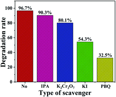
The trapping tests were also conducted to further investigate the active species that played a major role in the degradation of NO2. In the scavenger experiments, K2Cr2O7, KI, isopropyl alcohol (IPA) and p-benzoquinone (PBQ) served as the trapping reagents for the electrons (e−), photo-induced holes (h+), hydroxide radicals (˙OH) and superoxide radicals (˙O2−).64 From Fig. 10, it was observed that the NO2 degradation rates all exhibited varying degrees of decrease. We found that the degradation efficiency displayed an inconspicuous decrease with the addition of IPA, which manifested that ˙OH was not the dominant active species. The addition of K2Cr2O7 resulted in a slight decline in the NO2 removal rate, indicating that e− was an active species. However, after the addition of KI, the fairly obvious decrease of the NO2 degradation rate was noticed, which proved that h+ greatly contributed to the NO2 photocatalytic degradation. Furthermore, the rate presented the most significant reduction in the presence of PBQ, which demonstrated that ˙O2− played the most significant role in the NO2 photodegradation over the TaON/CdS/ZnS film under the illumination of visible light.
From the discussion above, we can conclude that the TaON/CdS/ZnS film exhibited superior photocatalytic activity for NO2 elimination under visible light irradiation. The possible charge carrier transfer mechanisms for the significantly improved photocatalytic performance of the TaON/CdS/ZnS photocatalytic film are illustrated in detail in Fig. 11. The trapping tests suggested that ˙O2− played the most significant role in NO2 photodegradation over the TaON/CdS/ZnS film. The conduction band (CB) position of TaON (−0.3 V) is more positive than the O2/˙O2− (−0.33 V vs. NHE) position, thus the electrons in the CB of TaON cannot reduce O2 to ˙O2−.55,65 Therefore, a direct Z-scheme transfer mechanism could be constructed to explain the enhanced photocatalytic activity for NO2 elimination.66,67 At first, CdS and TaON were excited to produce photoinduced carriers under the irradiation of visible light, and the electrons in the CB of TaON recombined immediately with the photoinduced holes on the VB of CdS, which greatly promoted the effective separation of photogenerated electron–hole pairs. Then, due to the more negative CB position (−0.9 V), the electrons in the CB of CdS were captured by O2 to promote the formation of active species ˙O2− on the photocatalytic film surface, and NO2 molecules reacted with ˙O2−, producing the final degradation products. At the same time, the remaining photogenerated holes in the valence band (VB) of TaON will also be used to remove NO2. There are some zinc vacancies (VZn) and interstitial sulfur vacancies (Is) in the ZnS passivation layer that serve as hole acceptors produced in CdS.68 Therefore, the holes in the VB of CdS partly migrate directly to (VZn) and (Is) in ZnS, which greatly facilitates the effective charge separation and ZnS displays excellent resistance to the reduced photo-corrosion of CdS. Therefore, the proposed mechanism above is probably responsible for the extraordinary photocatalytic degradation of NO2 for TaON/CdS/ZnS film.
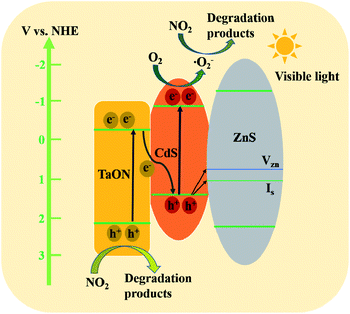 | ||
| Fig. 11 A possible schematic diagram for NO2 photodegradation over the TaON/CdS/ZnS film under the irradiation of visible light. | ||
Conclusions
Orange TaON powder with a large number of nanopores was successfully synthesized by a simple method of heating Ta2O5 powder in an NH3 atmosphere, and the pure TaON film was prepared using the doctor-blade method. The TaON/CdS and TaON/CdS/ZnS photocatalytic films were prepared by the successive ionic layer adsorption and reaction (SILAR) method for the first time. Several sets of photoelectrochemical experiments, such as PL, I–t and EIS, were carried out to investigate the photoelectric performance of all the prepared films, which all powerfully illustrated that the TaON/CdS/ZnS photocatalytic films possessed highly efficient photo-generated charge separation and transfer capacities. We also studied the photocatalytic performance of all the films, and the TaON/CdS/ZnS composite film exhibited the highest NO2 photodegradation efficiency (achieving about 96.7% after only 2 h illumination), which was better than the bare TaON and TaON/CdS films. The repeated NO2 degradation measurements fully demonstrated that the TaON/CdS/ZnS composite film presented extraordinary stability during four cycling tests. In summary, the simple and inexpensive syntheses of orange TaON and composite films with excellent photocatalytic performance have been successfully carried out. This indicates that with CdS deposition and ZnS passivation on TaON film, this architecture has opened up interesting and promising perspectives for their potential application in urban pollutant elimination.Conflicts of interest
There are no conflicts to declare.Acknowledgements
This project is financially supported by the Natural Science Foundation of China (grant no. 21571029 and 21671035).Notes and references
- Y. Shen, H. Bi, T. Li, X. Zhong, X. Chen, A. Fan and D. Wei, Appl. Surf. Sci., 2018, 434, 922–931 CrossRef CAS.
- S. W. Lee, W. Li, Y. Hong, G. Lee and D. S. Yoon, Sens. Actuators, B, 2018, 255, 1788–1804 CrossRef CAS.
- Y. Shen, X. Zhong, J. Zhang, T. Li, S. Zhao, B. Cui, D. Wei, Y. Zhang and K. Wei, Appl. Surf. Sci., 2019, 498, 143873 CrossRef CAS.
- W. Zeng, Y. Liu, J. Mei, C. Tang, K. Luo, S. Li, H. Zhan and Z. He, Sens. Actuators, B, 2019, 301, 127010 CrossRef CAS.
- J. Wang, Y. Shen, X. Li, Y. Xia and C. Yang, Sens. Actuators, B, 2019, 298, 126858 CrossRef CAS.
- X. Zhu, L. Zhang, M. Zhang and C. Ma, Fuel, 2019, 258, 116109 CrossRef CAS.
- Y. Zhang, Y. Yu, W. Shan, Z. Lian and H. He, Catal. Today, 2020, 339, 135–147 CrossRef CAS.
- N. Li, C. N. Maesano, R. Friedrich, E. Medda, S. Brandstetter, M. Kabesch, C. Apfelbacher, M. Melter, B. Seelbach-Göbel, I. Annesi-Maesano and D. Sarigiannis, Environ. Res., 2019, 178, 108629 CrossRef CAS.
- G. Qian, H. Yu, X. Gong and L. Zhao, Constr. Build. Mater., 2019, 218, 53–63 CrossRef CAS.
- G. Xiao, A. Huang, H. Su and T. Tan, Build. Environ., 2013, 65, 215–221 CrossRef.
- W. Liu, S. Wang, J. Zhang and J. Fan, Constr. Build. Mater., 2015, 81, 224–232 CrossRef.
- M. M. Ballari, M. Hunger, G. Hüsken and H. J. H. Brouwers, Appl. Catal., B, 2010, 95, 245–254 CrossRef CAS.
- Y. Zou, Y. Xie, S. Yu, L. Chen, W. Cui, F. Dong and Y. Zhou, Appl. Surf. Sci., 2019, 496, 143630 CrossRef CAS.
- M. M. Ballari, Q. L. Yu and H. J. H. Brouwers, Catal. Today, 2011, 161, 175–180 CrossRef CAS.
- L. Wang, G. Xu, J. Ma, Y. Yu, Q. Ma, K. Liu, C. Zhang and H. He, Environ. Sci. Technol., 2019, 53, 10855–10862 CrossRef CAS.
- F. Guo, M. Li, H. Ren, X. Huang, W. Hou, C. Wang, W. Shi and C. Lu, Appl. Surf. Sci., 2019, 491, 88–94 CrossRef CAS.
- F. Guo, X. Huang, Z. Chen, H. Ren, M. Li and L. Chen, J. Hazard. Mater., 2020, 390, 122158 CrossRef CAS.
- F. Guo, M. Li, H. Ren, X. Huang, K. Shu, W. Shi and C. Lu, Sep. Purif. Technol., 2019, 228, 115770 CrossRef CAS.
- W. Shi, H. Ren, M. Li, K. Shu, Y. Xu, C. Yan and Y. Tang, Chem. Eng. J., 2020, 382, 122876 CrossRef CAS.
- L. Pei, H. Wang, X. Wang, Z. Xu, S. Yan and Z. Zou, Dalton Trans., 2018, 47, 8949–8955 RSC.
- S. S. Gujral, A. N. Simonov, Xi-Ya Fang, M. Higashi, T. Gengenbach, R. Abe and L. Spiccia, Catal. Sci. Technol., 2016, 6, 3745–3757 RSC.
- E. S. Kim, N. Nishimura, G. Magesh, J. Y. Kim, Ji-W. Jang, H. Jun, J. Kubota, K. Domen and J. S. Lee, J. Am. Chem. Soc., 2013, 135, 5375–5383 CrossRef CAS.
- J. J. Bown and A. J. Page, J. Mater. Chem. A, 2019, 7, 13029–13035 RSC.
- G. Sahara, H. Kumagai, K. Maeda, N. Kaeffer, V. Artero, M. Higashi, R. Abe and O. Ishitani, J. Am. Chem. Soc., 2016, 138, 14152–14158 CrossRef CAS.
- W. Chen, M. Chu, L. Gao, L. Mao, J. Yuan and W. Shangguan, Appl. Surf. Sci., 2015, 324, 432–437 CrossRef CAS.
- Y. Liu, Y. Zhou, G. Chen, T. Guo, L. Wang, X. Huang and W. Zeng, Mater. Lett., 2015, 148, 155–158 CrossRef CAS.
- W. Shi, M. Li, X. Huang, H. Ren, C. Yan and F. Guo, Chem. Eng. J., 2020, 382, 122960 CrossRef.
- W. Shi, F. Guo, M. Li, Y. Shi, M. Shi and C. Yan, Appl. Surf. Sci., 2019, 473, 928–933 CrossRef CAS.
- S. S. Gujral, A. N. Simonov, M. Higashi, Xi-Ya Fang, R. Abe and L. Spiccia, ACS Catal., 2016, 6, 3404–3417 CrossRef CAS.
- M. Higashi, K. Domen and R. Abe, J. Am. Chem. Soc., 2012, 134, 6968–6971 CrossRef CAS.
- G. Suo, D. Li, L. Feng, X. Hou, X. Ye, L. Zhang, Q. Yu, Y. Yang and W. Wang, J. Mater. Sci. Technol., 2020, 55, 167–172 CrossRef.
- G. Suo, J. Zhang, D. Li, Q. Yu, M. He, L. Feng, X. Hou, Y. Yang, X. Ye, L. Zhang and W. Wang, J. Colloid Interface Sci., 2020, 566, 427–433 CrossRef CAS.
- D. Li, J. Zhang, S. M. Ahmed, G. Suo, W. Wang, L. Feng, X. Hou, Y. Yang, X. Ye and L. Zhang, J. Colloid Interface Sci., 2020, 574, 174–181 CrossRef CAS.
- H. Wang, Y. Xia, X. Wang, Y. Han, X. Jiao and D. Chen, ACS Appl. Mater. Interfaces, 2019, 11, 33062–33073 CrossRef CAS.
- L. Pei, T. Li, Y. Yuan, T. Yang, J. Zhong, Z. Ji, S. Yan and Z. Zou, Chem. Commun., 2019, 55, 11754–11757 RSC.
- J. Hou, C. Yang, H. Cheng, S. Jiao, O. Takeda and H. Zhu, Energy Environ. Sci., 2014, 7, 3758–3768 RSC.
- Y. Chen, L. Tan, M. Sun, C. Lu, J. Kou and Z. Xu, J. Mater. Sci., 2019, 54, 5321–5330 CrossRef CAS.
- Y. Li, H. Wang, Q. Feng, G. Zhou and Z. Wang, ACS Appl. Mater. Interfaces, 2013, 5, 8217–8224 CrossRef CAS.
- Y. Xie, Z. Yu, G. Liu, X. Ma and H. Cheng, Energy Environ. Sci., 2014, 7, 1895–1901 RSC.
- W. Shi, F. Guo, M. Li, Y. Shi and Y. Tang, Sep. Purif. Technol., 2019, 212, 142–149 CrossRef CAS.
- H. J. Lee, J. Bang, J. Park, S. Kim and S. Park, Chem. Mater., 2010, 22, 5636–5643 CrossRef CAS.
- A. J. Yost, T. K. Ekanayaka, G. Gurung, G. Rimal, S. Horoz, J. Tang, T. Paudel and T. Chien, J. Phys. Chem. C, 2019, 123, 24890–24898 CrossRef CAS.
- S. V. P. Vattikuti, C. Byon, C. V. Reddy and R. V. S. S. N. Ravikumar, RSC Adv., 2015, 5(105), 86675–86684 RSC.
- B. Poornaprakash, U. Chalapathi, P. T. Poojitha, S. V. P. Vattikuti and S.-H. Park, Mater. Sci. Semicond. Process., 2019, 100, 73–78 CrossRef CAS.
- J. Zhang, L. Wang, X. Liu, X. Liu and W. Huang, J. Mater. Chem. A, 2015, 3, 535–541 RSC.
- J. Hou, H. Zhao, F. Huang, L. Chen, Q. Wu, Z. Liu, S. Peng, N. Wang and G. Cao, J. Mater. Chem. A, 2018, 6, 9866–9873 RSC.
- J. Huang, K. L. Mulfort, P. Du and L. X. Chen, J. Am. Chem. Soc., 2012, 134, 16472–16475 CrossRef CAS.
- Q. Zhou, L. Li, Z. Xin, Y. Yu, L. Wang and W. Zhang, J. Alloys Compd., 2020, 813, 152190 CrossRef CAS.
- B. Poornaprakash, U. Chalapathi, S. V. P. Vattikuti, M. C. Sekhar, B. P. Reddy, P. T. Poojitha, M. S. P. Reddy, Y. Suh and S.-H. Park, Ceram. Int., 2019, 45(2), 2289–2294 CrossRef CAS.
- S. V. P. Vattikutin, C. Byonn and S. Jeon, Phys. B, 2016, 502, 103–112 CrossRef.
- B. Poornaprakash, U. Chalapathi, Y. Suh, S. V. P. Vattikuti, M. S. P. Reddy and S.-H. Park, Ceram. Int., 2018, 44(10), 11724–11729 CrossRef CAS.
- J. Hou, Z. Wang, W. Kan, S. Jiao, H. Zhu and R. V. Kumar, J. Mater. Chem., 2012, 22, 7291–7299 RSC.
- Z. Wang, J. Hou, C. Yang, S. Jiao and H. Zhu, Chem. Commun., 2014, 50, 1731–1734 RSC.
- L. An, X. Han, Y. Li, C. Hou, H. Wang and Q. Zhang, J. Sol-Gel Sci. Technol., 2019, 91, 82–91 CrossRef CAS.
- S. Wang, Z. Li, Y. Guan, L. Lu, Z. Shi, P. Weng, S. Yan and Z. Zou, Appl. Catal., B, 2019, 245, 220–226 CrossRef CAS.
- B. Fang, Y. Xing, A. Bonakdarpour, S. Zhang and D. P. Wilkinson, ACS Sustainable Chem. Eng., 2015, 3, 2381–2388 CrossRef CAS.
- B. Fang, A. Bonakdarpour, K. Reilly, Y. Xing, F. Taghipour and D. P. Wilkinson, ACS Appl. Mater. Interfaces, 2014, 6, 15488–15498 CrossRef CAS.
- B. Fang, M. Kim, S. Fan, J. H. Kim, D. P. Wilkinson, J. Ko and J.-S. Yu, J. Mater. Chem., 2011, 21, 8742–8748 RSC.
- J. H. Kim, B. Fang, M. Kim and J.-S. Yu, Catal. Today, 2009, 146, 25–30 CrossRef CAS.
- B. Fang, J. H. Kim, M.-S. Kim and J.-S. Yu, Acc. Chem. Res., 2013, 46, 1397–1406 CrossRef CAS.
- H.-M. Lee, H.-J. Jeong, K.-C. Ok, Y. S. Rim and J.-S. Park, ACS Appl. Mater. Interfaces, 2018, 10, 30541–30547 CrossRef CAS.
- K. Maeda, M. Higashi, D. Lu, R. Abe and K. Domen, J. Am. Chem. Soc., 2010, 132, 5858–5868 CrossRef CAS.
- L. Xi, Q. Zhang, Z. Sun, C. Song and L. Xu, ChemElectroChem, 2018, 5, 2534–2541 CrossRef CAS.
- G. Zhu, M. Hojamberdiev, S. Zhang, S. T. U. Din and W. Yang, Appl. Surf. Sci., 2019, 467–468, 968–978 CrossRef CAS.
- Y. Yu, W. Ouyang, Z. Liao, B. Du and W. Zhang, ACS Appl. Mater. Interfaces, 2014, 6, 8467–8474 CrossRef CAS.
- T. M. Di, Q. L. Xu, W. K. Ho, H. Tang, Q. J. Xiang and J. G. Yu, ChemCatChem, 2019, 11, 1394–1411 CrossRef CAS.
- T. Wei, Z. Jin, F. Li, D. Yan and L. Xu, Photochem. Photobiol. Sci., 2020, 19, 80–87 RSC.
- D. Jiang, Z. Sun, H. Jia, D. Lu and P. Du, J. Mater. Chem. A, 2016, 4, 675–683 RSC.
Footnotes |
| † Electronic supplementary information (ESI) available. See DOI: 10.1039/d0ra01056a |
| ‡ These authors contributed equally to this work. |
| This journal is © The Royal Society of Chemistry 2020 |

