
 Open Access Article
 This Open Access Article is licensed under a Creative Commons Attribution-Non Commercial 3.0 Unported Licence
Microwave-assisted catalytic conversion of glucose to 5-hydroxymethylfurfural using “three dimensional” graphene oxide hybrid catalysts†
Yui Hirano*a,
Jorge N. Beltraminiab,
Atsushi Moria,
Manami Nakamuraa,
Mohammad Razaul Karim cd,
Yang Kima,
Masaaki Nakamuraa and
Shinya Hayami*ae
cd,
Yang Kima,
Masaaki Nakamuraa and
Shinya Hayami*ae
aDepartment of Chemistry, Graduate School of Science and Technology, Kumamoto University, 2-39-1 Kurokami, Chuo-ku, Kumamoto 860-8555, Japan. E-mail: hayami@kumamoto-u.ac.jp
bCentre for Tropical Crops and Bio-Commodities, Queensland University of Technology, Brisbane, 4000, Australia
cChemistry Department, King Abdulaziz University, Jeddah 21589, Saudi Arabia
dDepartment of Chemistry, School of Physical Sciences, Shahjalal University of Science and Technology, Sylhet-3114, Bangladesh
eInstitute of Pulsed Power Science (IPPS), Kumamoto University, 2-39-1 Kurokami, Chuo-ku, Kumamoto 860-8555, Japan
First published on 31st March 2020
Abstract
Hybrids of reduced graphene oxide (rGO) and metal/metal oxide (Pt, NiO/Ni(OH)2, CoO, Fe3O4) nano particle were prepared by reduction of graphene oxide (GO) and metal ion (Pt2+, Ni2+, Co2+, Fe2+) hybrids. The M-rGO hybrids (M = Pt, Ni–, Co and Fe) were justified for the transformation of glucose to 5-hydroxymethylfurfural (5-HMF). High glucose → 5-HMF conversion was yielded depending on the nature of the M-rGO catalyst. The Ni-rGO showed the highest 5-HMF yield. The conversion reaction tuned to the optimized state under a microwave-assisted reaction accomplished by using Ni-rGO. In such case, the conversion rate was 99% with a 5-HMF yield of 75%. In order to improve both the conversion and yield, NiGO-FD was prepared by a freeze-dry method. The NiGO-FD remarkably showed the highest conversion of 99% and 5-HMF yield of 95%. Beside the biomass transformation process, the physico-chemical strategy employed herein for multiplying the catalytic efficiency might be justified for catalyzing similar reactions.
1. Introduction
The current oil price volatility combined with high-level greenhouse gas emissions increases the possibility of an energy crisis amidst soaring global energy consumption that has driven the need to seek alternative energy sources. As such, lignocellulosic biomass is a promising renewable feedstock for both carbon-based energy sources and sustainable chemical production. One of the main challenges in converting lignocellulosic biomass is producing chemicals or fuels at high selectivities and yields at economical costs. This happens because of the recalcitrance of lignocellulosic biomass, thus requiring both physical and chemical pretreatments, which are still one of the most expensive stages of biomass conversion strategy. Typically, two-step processing methods are employed to control the reactivity of lignocellulosics and improve product selectivity.1 These methods first fractionate the lignocellulosics into its main components, cellulose, hemicellulose and lignin, which allows for processing each fraction at different conditions to achieve high yields of target products.2Cellulose accounts for 30–50 wt% of lignocellulosic biomass and is a linear homopolymer made up of anhydro-D-glucopyranose units linked via β-glycosidic bonds.3 Cellulose has a degree of polymerization (DP) up to 15![[thin space (1/6-em)]](https://www.rsc.org/images/entities/char_2009.gif) 000 glucopyranose units4 with a network of intra- and inter-molecular hydrogen bonding. The formation of intramolecular hydrogen bonding within cellulose structure is responsible for its crystallinity, rigidity and chemical inertness.5 Cellulose can be converted into glucose by chemical or enzymatic hydrolysis6,7 and can be used to produce ethanol, platform chemicals, such as levulinic acid (LA) and 5-hydroxymethylfurfural (5-HMF), and liquid fuels.8,9 Amongst the numerous routes of lignocellulosic biomass valorization, catalytic dehydration of cellulose to produce 5-hydroxymethylfurfural (5-HMF) represents an attractive strategy.10,11 This is because of the versatility of using 5-HMF as an important platform molecule to synthesize an array of intermediate chemicals, from which a diverse range of biofuels as well as commodity and fine chemicals can be generated as shown in Scheme 1. For example, 5-HMF can be selectively oxidized to furan-2,5-dicarboxylic acid (FDCA) which may be used as a replacement for terephthalic acid in the production of polyethyleneterephthalate.12 Alternatively, 5-HMF can be reduced to 2,5-bis(hydroxymethyl)furan (BHMF) and 2,5-bis(hydroxymethyl)tetrahydrofuran (BHMTF) wherein both can serve as alcohol components in the production of polyesters, providing completely biomass-derived polymers when combined with FDCA.13 5-HMF may also be rehydrated to levulinic acid from which gamma valerolactone can be produced, which can be utilized as a solvent and fuel additives.14 Another important derivative of 5-HMF is 2,5-dimethylfuran (DMF) and 2-methylfuran (2-MF), and both are potential liquid transportation fuels.15 Moreover, 5-HMF can also serve as a precursor in the synthesis of liquid alkanes for use as diesel fuel.16
000 glucopyranose units4 with a network of intra- and inter-molecular hydrogen bonding. The formation of intramolecular hydrogen bonding within cellulose structure is responsible for its crystallinity, rigidity and chemical inertness.5 Cellulose can be converted into glucose by chemical or enzymatic hydrolysis6,7 and can be used to produce ethanol, platform chemicals, such as levulinic acid (LA) and 5-hydroxymethylfurfural (5-HMF), and liquid fuels.8,9 Amongst the numerous routes of lignocellulosic biomass valorization, catalytic dehydration of cellulose to produce 5-hydroxymethylfurfural (5-HMF) represents an attractive strategy.10,11 This is because of the versatility of using 5-HMF as an important platform molecule to synthesize an array of intermediate chemicals, from which a diverse range of biofuels as well as commodity and fine chemicals can be generated as shown in Scheme 1. For example, 5-HMF can be selectively oxidized to furan-2,5-dicarboxylic acid (FDCA) which may be used as a replacement for terephthalic acid in the production of polyethyleneterephthalate.12 Alternatively, 5-HMF can be reduced to 2,5-bis(hydroxymethyl)furan (BHMF) and 2,5-bis(hydroxymethyl)tetrahydrofuran (BHMTF) wherein both can serve as alcohol components in the production of polyesters, providing completely biomass-derived polymers when combined with FDCA.13 5-HMF may also be rehydrated to levulinic acid from which gamma valerolactone can be produced, which can be utilized as a solvent and fuel additives.14 Another important derivative of 5-HMF is 2,5-dimethylfuran (DMF) and 2-methylfuran (2-MF), and both are potential liquid transportation fuels.15 Moreover, 5-HMF can also serve as a precursor in the synthesis of liquid alkanes for use as diesel fuel.16
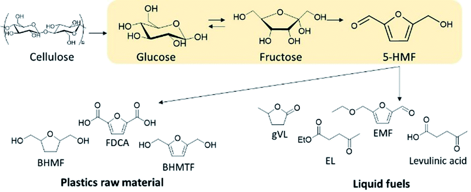 | ||
| Scheme 1 5-HMF production and its utilization routes for biochemicals and fuels. | ||
5-HMF is preferentially obtained by acid-catalyzed dehydration of C6 carbohydrates, such as fructose and glucose using a variety of homogeneous and heterogenous catalysts.17,18 However, because the synthesis efficiency of 5-HMF is poor with low selectivity and yield, it is crucial to develop a low-cost and highly efficient synthesis method. Over the years different heterogeneous catalysts such as metal-supported mesoporous zeolites, oxides, zeolites, ion exchange resins were extensively investigated to improve 5-HMF conversion and selectivity.19–22 From the results, it was clearly concluded that if a carbohydrate (cellulose, glucose, starch) was used as feed, a balance is needed between the Lewis and Brønsted acid sites to isomerize glucose to fructose and dehydrate fructose to 5-HMF respectively.23,24 It is also well known that the support plays a critical role in the catalytic performance of a heterogeneous catalyst.25
As a new member of the carbon family, the outstanding properties of graphene make it an ideal candidate to support catalyst and metal precursors.26,27 Graphene is a two-dimensional crystal that can be considered as a building block for carbon materials of different structures. Graphene has been known for long time since graphite is formed by a combination of graphenes with van der Waals forces. However, details of the properties were unclear until late years, because an isolation procedure of graphene from graphite was not well developed for long time.28 As such, recently, graphene has attracted comprehensive research interest because of its extraordinary thermal, mechanical, electronic, and optical properties.29 Metal supported graphene nanocomposites are a newly group of catalysts subject to current research.30 The inherent properties of graphene can be enhanced by using it as a support for metal nanoparticles. The large contact area provided by the planar structure of graphene sheets can act as a wonderful support for trapping guest metal particles.31 Moreover, graphene sheets have the unique ability to promote fast electron-transfer kinetics for a wide range of electroactive species. In addition, the oxygen functional group on the graphene oxide (GO) surface can be deoxygenated by heat, light, hydrazine, and it becomes reduced type graphene oxide (rGO), where its many defect structure has a high electron conductivity property. Furthermore, since rGO has a two-dimensional structure, it can not only provide surface area by doping a metal but also is useful as a reaction field, and it is expected that it can be used as a catalyst with higher activity than the conventional commercial catalyst.32 Thus, metal-supported graphene oxide (M-GO) composite materials have been widely used in different applications because of their high surface area, stability under ambient conditions, and faster electron-transport mechanism. Enhanced catalytic activities of several metal such as Pd, Pt, Ni, Au, Ru supported on rGO have been reported recently.33,34
Hence, in this work we focused on the effect of the synthesis techniques of M-rGO (Pt, Ni, Co and Fe) for the microwave-assisted catalytic decomposition of carbohydrates to 5-HMF, where the effect of reaction conditions, amount of catalyst used, effect of solvent, were also evaluated.
2. Experimental section
2.1. Materials
The synthesis of M-rGO and on graphene oxide freeze-dried (MGO-FD) are illustrated in Fig. S1.† In short, a metal chloride solution containing the prescribed amount of metal was added into the GO dispersion as both linkages among graphene sheets and metal precursors. As depicted in Scheme 2, during the synthesis of M-rGO after reduction at 120 °C with hydrazine solution under mild reaction conditions, a gel-like structure could be formed between metal and rGO as a result of connecting rGO sheets with metal ions.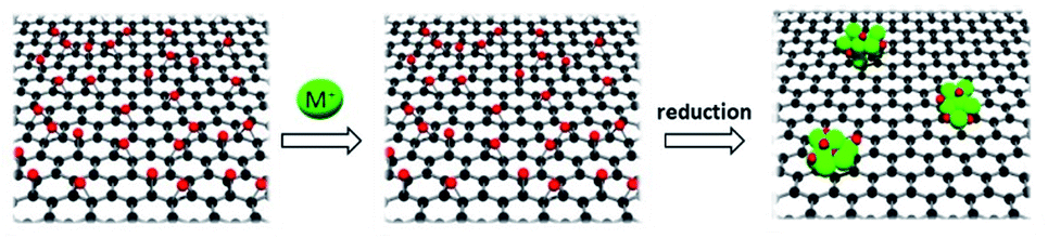 | ||
| Scheme 2 Synthetic strategy for M-rGO. | ||
2.2. Synthesis of graphene oxide
Graphene oxide was prepared by the modified Hummers' method (Scheme 1).35 1 g of graphite powder (95%) and 1 g of NaNO3 were mixed in a 500 mL round-bottom flask placed into an ice bath. 50 mL of conc. H2SO4 was added to it and the mixture was stirred for 30 min at 0 °C. Afterward, 7 g KMnO4 was added and the mixture was then stirred for 40 min at 35 °C. As such, 50 mL of distilled water was slowly added, and the mixture was stirred for another 30 min at 90 °C. The reaction was stopped by adding 100 mL of distilled water followed by 3 mL of 30% H2O2 solution. The mixture was cooled at room temperature. After cooling, the product was centrifuged at 3000 rpm to remove the supernatant liquid. The remaining solid mixture was washed with distilled water and centrifuged at 3000 rpm to remove the supernatant liquid 3 times. The obtained solution was added into a 500 mL Erlenmeyer flask and sonicated in an ultrasound bath for 2 h. This dispersion was centrifuged at 8000 rpm for 1 h to remove the impurities. This supernatant liquid was called graphene oxide (GO) dispersion.2.3. Synthesis of M-rGO hybrids
A 100 mL GO solution was mixed with 100 mg of metal chloride solutions (NiCl2, CoCl2, FeCl2) to prepare M-GO solution. To this M-GO solution, 10 mL hydrazine was added, and the mixture was refluxed for 3 days at 120 °C. After filtering the powder thus obtained was the M-rGO solution.2.4. Synthesis of NiGO-FD
100 mL GO solution (1 g L−1) was mixed with 100 mg nickel chloride (NiCl2). Obtained Ni-GO solution was freeze-dried by placing the solution in a freeze-drying flask rotated in a bath, with cooling facilities using dry ice. Afterward, the temperature was raised to remove any physico-chemical interactions that were formed between the water molecules and the frozen materials, and the resulted solid material was grounded to produce a NiGO-FD catalyst.2.5. Catalytic activity with procedure and product analysis
Instead of conventional heating methods, we employed microwave-assisted reactions. The heat transferring process in conventional heating is directly related to the diffusion of heat from the surface to bulk is comparatively slow and less effective. In contrast, microwave heating confirms some advantages including short reaction time, high selectivity and high yields. The microwaves lead to the vibration and rotational motion of polar molecules and can generate uniform heat in a very short time. The microwave heating tools that we employed were well equipped to control the W, Hz, time and temperature. When the power of the microwave was modulated in the range of 200 to 800 W, the yield for glucose generation was 2.5 to 4.5 wt%. The high glucose yield observed at 800 W could be likely due to the sudden uneven energy distribution and high-temperature gradient known as “hotspots” or thermal runaway. Thus, low MW power was utilized in the succeeding experiments to minimize this occurrence. An optimized reaction temperature of 200 °C was preferred based on the previous report.36 The microwave-assisted catalytic conversion of cellulose, glucose and fructose was carried out using microwave reaction vials. In a typical experimental run, 100 mg glucose, 4 mL solvent and 5 mg catalysts were charged into 10 mL reactor. After being sealed with a cap, the reactor containing the mixture was mounted in a microwave reactor apparatus (Biotage Initiator+) and heated at a specified reaction time under magnetic stirring. Time zero of the reaction was defined as the time when the reactor reached its set point temperature. Reactions were performed in triplicate to asses the reproducibility of results.The liquid samples were collected after reaction and the concentration of the product species were quantified using Agilent Technologies HPLC with a ZORBAX Eclipse Plus C18 as the analytical column and both RID (refractive index) and RID (UV-Vis) detectors. The HPLC was operated under the following conditions: oven temperature, 50 °C, mobile phase, 5 mM H2SO4; flow rate, 0.6 mL min−1; injection volume, 5 μL. The concentrations of glucose and 5-HMF were quantified through the external standard method and calibration curves of commercially available standard substrates.

3. Results and discussion
3.1. Characterization of M-rGO hybrid catalysts
The synthesis of M-rGO and on graphene oxide freeze-dried (MGO-FD) are illustrated in Fig. S1.† In short, a metal chloride solution containing the prescribed amount of metal was added into the GO dispersion as both linkages among graphene sheets and metal precursors. As depicted in Scheme 2, during the synthesis of M-rGO after reduction at 120 °C with hydrazine solution under mild reaction conditions, a gel-like structure could be formed between metal and rGO as a result of connecting rGO sheets with metal ions.On the other hand, another batch of GO was impregnated with nickel chloride solution as chosen metal and was subjected to freeze-dried conditions. With the freeze-dried technique, the 3D GO with uniform pore structure and larger surface area can be obtained.
FTIR spectra of the parent GO, NiGO-FD and Ni-rGO are shown in Fig. S2 and S3.† On NiGO-FD a strong adsorption band at around 3420 cm−1 was detected that corresponds to a hydrogen-bonded O–H stretching vibration, with a very weak same signal found for the case of Ni-rGO parent material. The band at 1048 cm−1 corresponds to C–O stretching vibration from C–O–C on the NiGO-FD and Ni-rGO respectively. Besides, a band at 1635 cm−1 of the C![[double bond, length as m-dash]](https://www.rsc.org/images/entities/char_e001.gif) C stretching vibration from the benzene ring skeleton of graphene, totally disappears in the case of Ni-rGO catalyst. As such, it is proved that GO was successfully modified by the use of the freeze-dried technique as confirmed also by Raman and SEM. analysis. The Raman spectra for GO, NiGO-FD and Ni-rGO catalysts illustrated in Fig. S4 and S5† also confirmed the findings from FTIR spectra. It is known that two of the most intense D band and G band Raman features can be ascribed to the characteristic peaks of graphene materials.35 The D/G intensity ratio of the NiGO-FD is 0.9, while on the Ni-rGO the corresponding ratio increases to 1.43. The freeze-dried of GO facilitates the restoration of sp2 carbon sites and the intensity of graphitic domains are smaller in size that the ones in Ni-rGO sample. The increase in D/G on Ni-rGO is consistent with the results reported by Chen et al.37 when studied GO reduction.
C stretching vibration from the benzene ring skeleton of graphene, totally disappears in the case of Ni-rGO catalyst. As such, it is proved that GO was successfully modified by the use of the freeze-dried technique as confirmed also by Raman and SEM. analysis. The Raman spectra for GO, NiGO-FD and Ni-rGO catalysts illustrated in Fig. S4 and S5† also confirmed the findings from FTIR spectra. It is known that two of the most intense D band and G band Raman features can be ascribed to the characteristic peaks of graphene materials.35 The D/G intensity ratio of the NiGO-FD is 0.9, while on the Ni-rGO the corresponding ratio increases to 1.43. The freeze-dried of GO facilitates the restoration of sp2 carbon sites and the intensity of graphitic domains are smaller in size that the ones in Ni-rGO sample. The increase in D/G on Ni-rGO is consistent with the results reported by Chen et al.37 when studied GO reduction.
Fig. 1a and b shows the SEM images of the Ni-rGO and NiGO-FD samples respectively. While the as-synthesized Ni-rGO exhibits the presence of GO nanosheets stack tightly due to strong π–π interaction between the Ni metal nanoparticles and GO nanosheets. The spherical metal precursors grow on GO with an average diameter of 100–250 nm. Fig. 1a reveals the presence of larger (≈250 nm) and smaller (≈100 nm) particles by ∼17% and 36% respectively. Particles having the intermediate sized were counted to be present by 47%. The NiGO-FD sample, confirmed the existence of a 3D structure revealing the presence of pores which are supposed to be created by the in situ self-assembly of graphene during the freeze-dried process. As observed by other researchers,38,39 it is assumed that the Ni metal nanoparticles could combine with the graphene oxide sheets to allows the formation of a 3D GO structure. These findings were confirmed by the BET surface area data where the total surface area of the NiGO-FD sample is greatly larger than that of the Ni-rGO, as a result of the formation of a 3D structure. On the other hand, Fig. 1c and d show TEM images of Ni-rGO and NiGO-FD individually. Fig. 1c indicates that the Ni-rGO is composed of folded single-layer nanosheets, whereas Fig. 1d reveals the folding and overlapping of the graphene sheets due to the freeze-drying process. In Fig. 1e and f, the selected EDX mapping from SEM confirmed the atomic percentage of Ni on the rGO surface in a well distributed area.
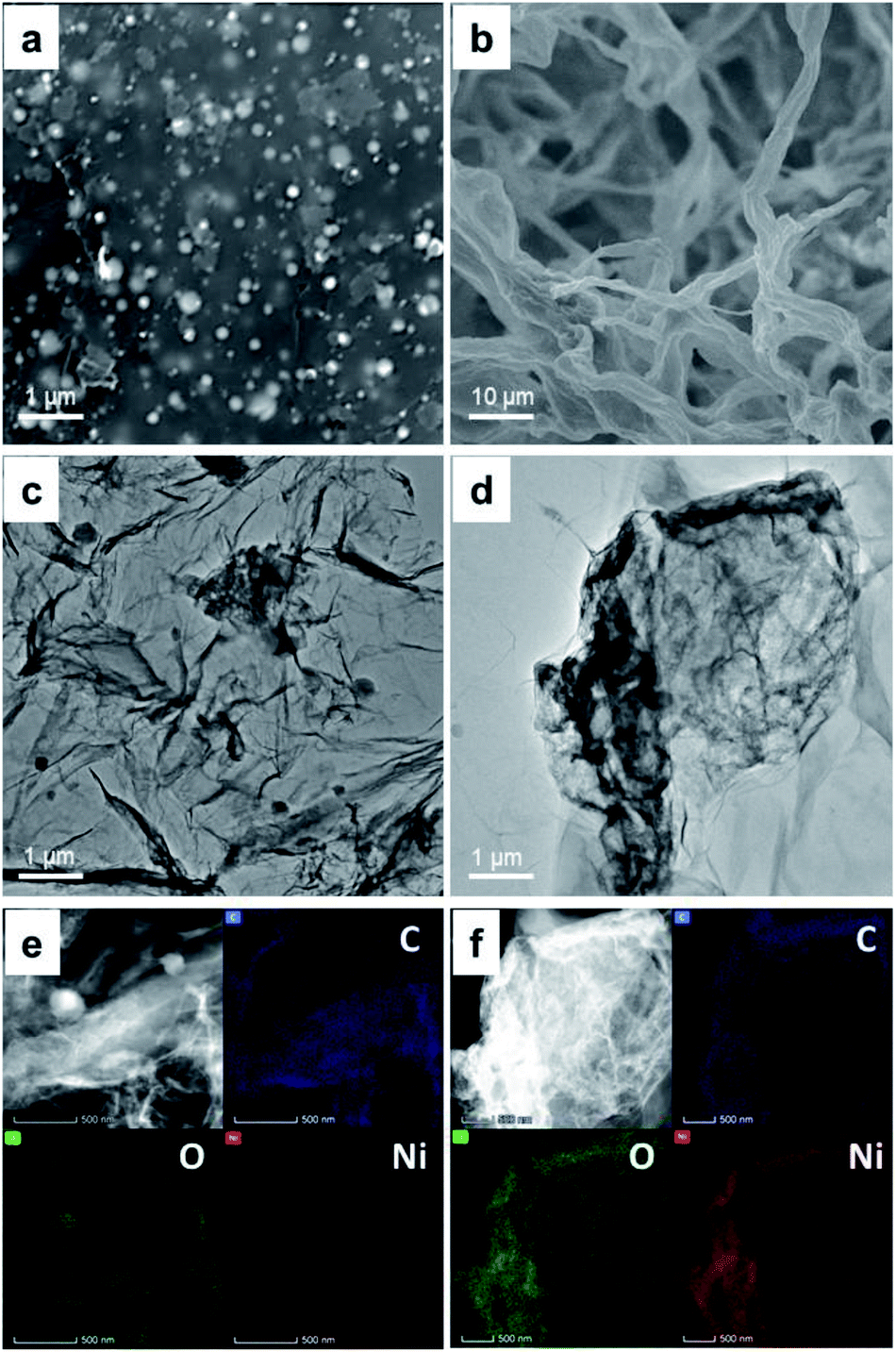 | ||
| Fig. 1 Surface morphology of Ni-rGO and NiGO-FD. SEM image of fresh metal Ni-GO (a) and NiGO-FD (b). HRTEM image of Ni-rGO (c) and NiGO-FD (d). EDX mapping of Ni-rGO (e) and NiGO-FD (f). | ||
The variation of elemental composition and functional groups were analyzed via XPS. As shown in Fig. S6 and S7,† on the C 1s spectra of the GO, NirGO and NiGO-FD seven different carbon entities: CC, C–H, C–C, C–OH, C–O–C, CO and OC–O can be clearly identified. In the case of Ni-rGO, the peaks of functional groups containing oxygen completely disappears or decreases and the peak intensity for CC dramatically increases, in agreement with Raman results that shows an increase in D/G, demonstrating that the GO reduction took place after treatment with hydrazine. On the other hand, on GONi-FD, the presence of carboxylic acid groups on GO is confirmed by the high intensity of CO functional group in agreement with FTIR results shown in Fig. S2.†
Then the presence and composition of the Ni on the GO samples was determined by XRD and XPS analysis and confirmed by TEM and TEM-EDX evaluation. It was found that XPS spectrum of the Ni 2p for NirGo and NiGO-FD samples (Fig. S8†) exhibit the characteristic peaks at 871.7 eV and 854.2 eV respectively that are assigned to Ni 2p1/2 and Ni 2p3/2.
These results clearly showed the presence of elemental state nickel in the structure of the composite GO catalysts after reduction and freeze-dried respectively. XRD patterns of the NirGO and NiGO-FD exhibited in Fig. S9 and S10† show a peak of GO at reflection (002) at 2θ = 25.4°, similar to previous reports.40,41 The reflection GO peak in the case of NiGO-FD is broader with the peak at 2θ = 23.3° which can suggest that there is a disordered stacking among the graphene sheets due to the formation of a 3D structure where the presence of Ni is also confirmed. The presence of Ni species was also confirmed by XRD analysis due to the formation of Ni-rGO as a consequence of reduction of NiO nanoparticles in the GO. The peaks at 44.49° (111) and 51.8° (200) 2θ (JCPDS no. 01-071-3740) along with the peak previously described at 25.4° for RGO layers confirmed the formation of reduced Ni-rGO. The XRD data is well supported by TEM and SEM observation (Fig. 1), where the presence of Ni nanoparticles decorated rGO sheets can be observed.
3.2. Catalytic properties of 2D M-GO materials
Metal supported on rGO and GO freeze-dried catalysts are potential candidates for the conversion of glucose into 5-HMF as they proved to be chemically stable and with a high functionalized surface area.42 We can hypothesize that due to the metal loaded and the formation of different oxygen functional groups on the graphene oxide surface as shown by XPS and XRD analysis, the hydrolysis of glucose to fructose and then the dehydration to 5-HMF can be facilitated by the combination of Lewis and Brønsted acid sites on the graphene oxide treated surface by reduction or by the freeze-dried technique. Initially, metal-supported rGO reduced by hydrazine treatment were studied for the conversion of glucose to 5-HMF using water as the reaction medium. The microwave reaction was performed at 200 °C temperature during 30 minutes with a catalyst loading of 5 mg for 100 mg of glucose in 4 mL of water as the solvent. Four hybrids were chosen. The performance of Pt-rGO, Ni-rGO, Co-rGO and Fe-rGO were compared with a blank control, a GO and rGO samples respectively. As can be seen in Fig. 2 under identical reaction conditions the addition of a metal to the GO influenced the catalytic activity, where all catalysts have increased glucose conversion and were more active toward producing 5-HMF than GO and rGO alone except for Pt. Table 1 clearly shows that the yield increases in the following order: Ni-rGO > Co-rGO > Fe-rGO > blank > Pt-rGO > rGO > GO.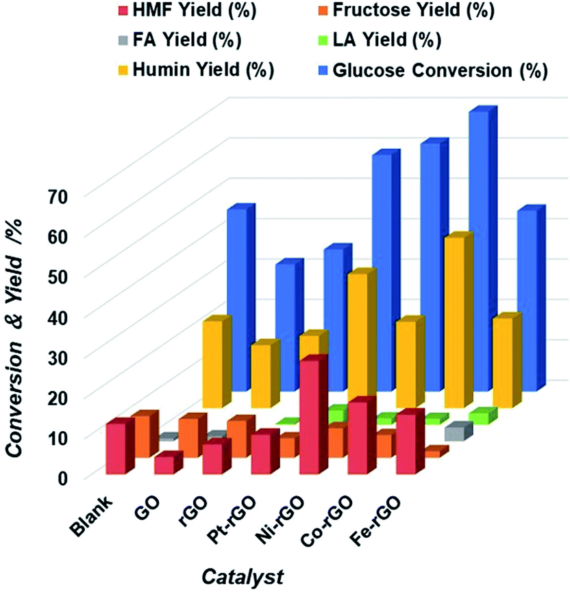 | ||
| Fig. 2 Extent of Glucose conversion and yield of 5-HMF and other products due to the catalytic action of M-rGO, blank, GO and rGO catalysts. | ||
| Catalyst | Glucose conversion (%) | HMF yield (%) | Fructose yield (%) | FA yield (%) | LA yield (%) | Humin yield (%) |
|---|---|---|---|---|---|---|
| Blank | 45.1 | 12.5 | 10.3 | 0.7 | 0.1 | 21.5 |
| GO | 31.5 | 4.3 | 9.6 | 1.2 | 0.8 | 15.6 |
| rGO | 35.2 | 7.4 | 9.1 | 0.6 | 0.2 | 17.9 |
| Pt-rGO | 58.6 | 9.8 | 4.8 | 7.3 | 3.5 | 33.2 |
| Ni-rGO | 61.4 | 28.1 | 7.3 | 3.1 | 1.5 | 21.4 |
| Co-rGO | 69.3 | 17.8 | 5.6 | 2.3 | 1.4 | 42.2 |
Somehow surprisingly, the 5-HMF yield obtained during the blank experiment was higher than those obtained for GO, rGO and Pt-rGO. This occurrence may be interpreted in relation to the metal and support properties of catalysts. rGO possesses a moderate concentration of acid sites that can dehydrate fructose, an initial product of glucose isomerization, into 5-HMF.
Hence, the concentration of fructose observed on Ni-rGO was lower when compared to Pt and Co on rGO respectively (Table 1). More so, with the presence of Co and Fe on rGO, 5-HMF rehydrates to produce levulinic acid that may also react with glucose or other reactive intermediates to form unwanted humin compounds. The high hydrogenolytic activity of Pt on rGO was confirmed by the presence of an increased yield of side furanic compounds, where the lowest 5-HMF yield of all metal rGO supported catalysts were found. Therefore, there is an upward trend of both the yield of levulinic acid and glucose conversion as shown in Table 1.
Regardless of the type of metal added to rGO, it is important to note that fructose conversion to 5-HMF occurred relatively faster in comparison to glucose isomerization. This indicates that glucose proceeds via fructose to produce 5-HMF. The mutual interaction of the pure metal and rGO provided a moderate acid concentration suitable for the glucose-to-5-HMF reaction. This cooperative interaction has been reported in literature, wherein glucose is isomerized to fructose with subsequent dehydration of fructose to 5-HMF.43,44 Fig. 2 and Table S1† also showed the individual metal rGO activity toward glucose conversion to 5-HMF. This preliminary experimental result encouraged us to investigate further how to optimize the 5-HMF yield and glucose conversion.
Next, we examined the role of the reaction medium on the formation rate of 5-HMF. Ni-rGO catalyst was chosen as showed the larger 5-HMF yield in water of all catalysts tested (Fig. 2). Initially, single water-lean aqueous medium was considered but the yield of 5-HMF found to be still relatively low. Therefore, tetrahydrofuran (THF) was chosen as a co-solvent and added to water in different ratios. It is known that THF lacks hydroxyl groups and has the potential to suppress side reactions.45 The addition of THF promoted a two solvent phases system; a reactive aqueous phase and an extractive organic phase. This allowed in situ extraction of 5-HMF from the aqueous phase into the organic phase, thereby preventing undesired side reactions from 5-HMF decomposition. Moreover, the continuous extraction shifts the reaction equilibrium to produce more 5-HMF. Fig. 3 clearly demonstrates the beneficial effect of adding THF, which results in 5-HMF yield increase up to about 70% at a near-complete glucose conversion. Not only does THF enable good partitioning of 5-HMF into the organic phase, but we also consider that the water reactive phase was modified by THF thereby minimizing degradation of 5-HMF into humins. The outcome of 5-HMF production using water–THF biphasic reaction system is promising and provides a step further towards achieving an efficient reaction medium for scaling-up.
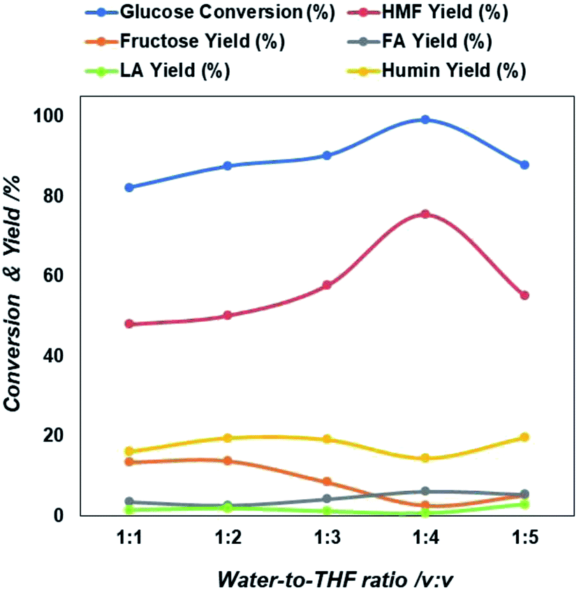 | ||
| Fig. 3 Extent of glucose conversion and yield of 5-HMF and other products due to the variation in solvent composition in terms of water to THF ration. | ||
As shown in Fig. 3, the 5-HMF yield increases from 22% to 67% when the water/THF ratio rises from 1:1 to 1:4 implying that the biphasic system worked successfully and prevented the 5-HMF decomposition in the organic phase. On the other hand, the ratio increases to 1:5, then 5-HMF yield and glucose conversion started to decrease. It is important to note that simultaneously levulinic acid and other compounds increases (Table S2†). In addition, it was observed that the water phase solution product colour changed from light yellow to brown, an indication that also an amount of byproducts principally humin compounds were formed. The decrease of 5-HMF yield with increasing the THF concentration in two phase solution may be due to a decreased transfer rate from the reacting water phase to the extracting THF phase due to formation of thicker layer partition, that favors also the simultaneous formation of intermediate compounds and other reactive intermediates via condensation, polymerization of glucose in the aqueous phase.46
3.3. Influence of 2D to 3D structural shifts on catalytic activities
Then, NiGO-FD catalyst synthesized by a freeze-dried technique was tested for the glucose conversion to 5-HMF using the biphasic water:THF = 1:4 and same reaction conditions as per the case of Ni-rGO catalyst where a glucose conversion of 100% and 5-HMF yield of 75% were achieved. As can be seen from results in Fig. 4 NiGO-FD proved to be substantially more active than Ni-rGO, with practically 99% glucose conversion and 5-HMF yield close to 95%. However, it is interesting to note in comparison GO-FD support have same catalytic behavior than rGO support.
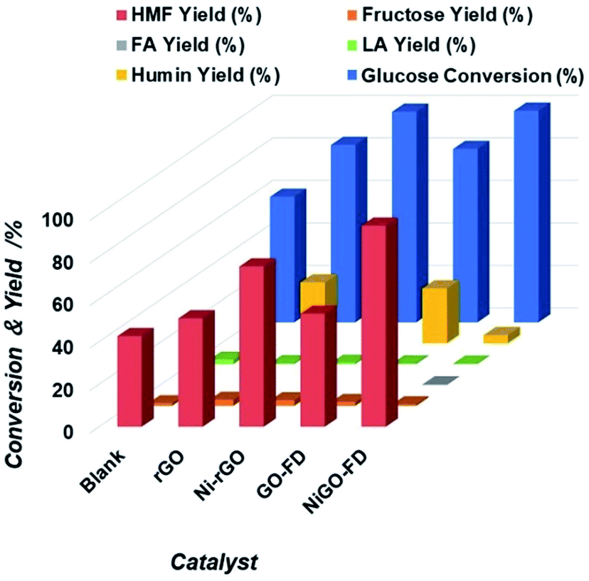 | ||
| Fig. 4 Extent of glucose conversion and yield of 5-HMF and other products due to the catalytic action of blank, rGO Ni-rGO, GO-FD and NiGO-FD catalysts. | ||
As a result, the sharp catalytic conversion of glucose and 5-HMF yield differences obtained when applying a freeze dried technique can be explained based on the properties and characterization of the NiGO-FD catalyst. As explained before, the large surface area and porosity found on the freeze-dried GO combined with the oxygen containing surface groups had an impact on its catalytic activity. These groups linked to Ni metal and Ni oxide might participate in the dehydration of fructose to 5-HMF, while the large surface area of GO freeze-dried may promote the conversion of glucose by increasing contact areas between reactants.42,43 As can be seen when comparing with Ni-rGO catalyst, mainly the reaction selectivity and yield were considerably lower than those under freeze dried treatment, as the GO reduced catalyst contains a lesser amount of oxygen groups on it surface as shown in Fig. 4 Furthermore this study, there are also several reports in the literature of how the surface of functionalized carbon materials play an important role in catalytic reactions, such as alcohol dehydration,44 isomerization.45 Then, due to its high 5-HMF catalytic yield (95%), NiGO-FD catalyst was chosen for the optimization reaction studies. For the study the biphasic water:THF system were used, but the reaction time, reaction temperature, catalyst loading and glucose concentration were changed in order to find the optimal reaction conditions for the conversion of glucose into 5-HMF. Fig. S11 and Table S1† show that the zeta potential for NiGO-FD measured at pH 3, 5, 7 and 9 were found to be −21.75, −22.79, −23.34 and −19.38 mV, respectively. The charge is optimized at a pH of 7, whereas it tends to the zero point at both the higher and lower pH value. No clear intersection at zero point is observed. The surface acidity of the materials-GO hybrid (20 wt%) in mmol unit (Table S2†) followed the trend as NiGO-FD (9.62) > Ni-rGO (2.68) > Co-rGO (2.47) > Fe-rGO (1.5) > Pt-rGO (1.39) > rGO (1.28).
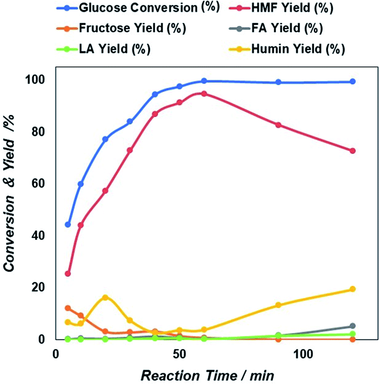 | ||
| Fig. 5 Reaction time dependent glucose conversion and yield of 5-HMF and other products due to the catalytic action of NiGO-FD catalysts. | ||
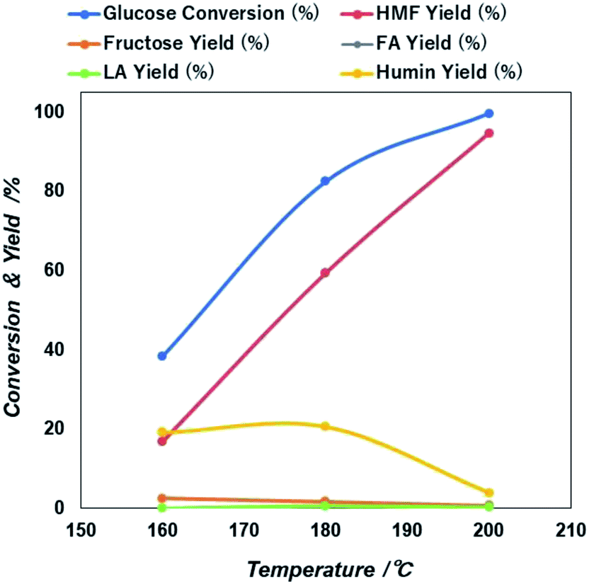 | ||
| Fig. 6 Reaction temperature dependent glucose conversion and yield of 5-HMF and other products due to the catalytic action of NiGO-FD catalysts. | ||
Then after increasing temperature to 180 °C there exists a sharp increase in both glucose conversion and 5-HMF yield that reach the maximum at 200 °C. This is an indication that longer time will be needed at a lower temperature, if would like to reach similar glucose conversion at higher temperature. However, as found previously47,48 because 5-HMF is more reactive at high temperature, a prolonged increase in the reaction temperature beyond 200 °C, can result in the decline of 5-HMF yield. Based on these results, an optimized microwave condition for this reaction was 60 minutes of reaction time at 200 °C. At these optimized conditions, we investigated also the effect of initial glucose concentration.
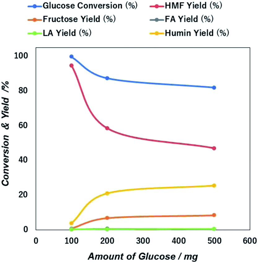 | ||
| Fig. 7 Initial concentration dependent glucose conversion and yield of 5-HMF and other products due to the catalytic action of NiGO-FD catalysts. | ||
The sharp loss of 5-HMF yield as a higher initial amount of glucose in the feed may be due to the propensity self-polymerization of 5-HMF or cross-polymerization between glucose, 5-HMF and other intermediates that will occur easily at a higher initial glucose concentrations, giving rise to the formation of brown-black soluble polymers and insoluble humin compounds in the aqueous phase.49,50
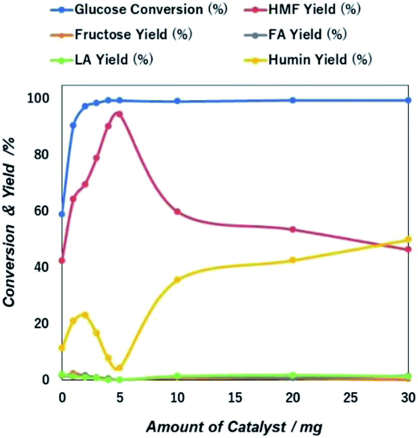 | ||
| Fig. 8 Catalyst mass dependent glucose conversion and yield of 5-HMF and other products due to the catalytic action of NiGO-FD catalysts. | ||
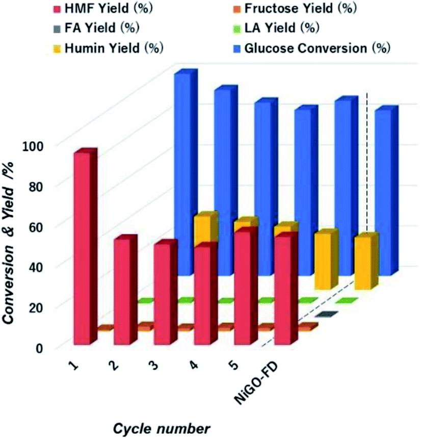 | ||
| Fig. 9 Extent of glucose conversion and yield of 5-HMF and other products with respect to cycle number during to the catalytic action of NiGO-FD catalysts. | ||
However, 5-HMF yield sharply declined over the first cycle runs from 95% to 55% and keeping constant that value for all remaining cycles. We visually observed a change in colour of the reaction solution from white to dark brown after first cycle. The likely cause of this is the formation and then deposition of humin compounds on the catalyst surface causing deactivation of the active sites after first cycle that caused the drop of 5-HMF yield as confirmed by. We hypothesized that the humins deposited on NiGO-FD catalyst surface is most likely affecting the dehydration step catalyzed by Brønsted acid from the functionalized organic oxygen groups. 5-HMF is reported to have stronger adsorption affinity onto Brønsted acid site.52 Afterwards, adsorbed 5-HMF on the surface of the recycled catalyst undergoes condensation reaction to humins, consistent with the catalyst colour change. The strongly adsorbed 5-HMF on the GO surface can also cause blockage of active sites as well as block catalyst pores that can undergo further rehydration reaction to organic acids. This is evidenced by the slightly increased yields of fructose and levulinic acid as experimentally detected. To test this hypothesis, we will be regenerating the catalyst in future experiments by removing any trace of humin compounds deposited on the catalyst surface before subsequent reaction runs, as catalyst deactivation by humin deposition is reversible by regeneration.
3.4. Comparison reported with catalytic systems
The competitive reported values for the conversion of glucose into 5-HMF is presented in Table 2. A glucose conversion of 100% and 5-HMF yield of 75% that we achieved by using NiGO-FD is competitively higher than some reported values. The benchmark values for both the conversion of glucose and 5-HMF yield as 100% were achieved by using P-VI-O/P-SO3H-154 catalyst in THF/DMSO system. However present work represents the possibility of obtaining non-expensive metal nanoparticle scaffolding GO-based catalysts.| Catalyst | Solvent | T (°C) | T (h) | Conversion (%) | 5-HMF yield (%) | Ref. |
|---|---|---|---|---|---|---|
| SnPO | EMIMBr | 120 | 3 | 94.1 | 58.3 | 53 |
| Sn-beta/HCl | Water | 140 | 2 | 72.0 | 11.0 | 54 |
| γ-Al2O3 | Water/MlBK/CaCl2 | 175 | 0.25 | 96.0 | 52.0 | 55 |
| TiO2–ZrO2/Amberlyst70 | THF/water | 175 | 3 | 99.9 | 85.9 | 56 |
| CrCl3·6H2O | TEAC | 130 | 0.16 | 95.0 | 71.5 | 57 |
| P-VI-O/P-SO3H-154 | THF/DMSO | 100 | 10 | 100 | 95.4 | 58 |
4. Conclusions
We demonstrated the conversion of glucose to 5-HMF in the water-THF biphasic system catalyzed by Ni nanoparticles supported on GO NP synthesized by freeze-dried method. Modification of GO was achieved creating a 3D structure with large surface area interconnected pores. Nickel metal was successfully incorporated into the GO surface as confirmed by XPS, XRD and microscopy analysis. Furthermore, active catalytic sites with Lewis and Brønsted type functionalities were created on the GO surface as a result of the presence of oxygen functional groups as confirmed by XPS that was highly effective for the catalytic conversion of glucose to 5-HMF in comparison with classical Ni-rGO structures. We also studied the effects of temperature, time, amount of catalyst weight and glucose substrate concentration. In general, all these parameters influence catalytic performance and yield of 5-HMF. Under optimized reaction conditions, remarkable high 5-HMF yield of ca. 95% and 100% glucose conversion was achieved in a biphasic water–THF system. Under comparable microwave reaction conditions, 5-HMF yield of 55% and 45% was attained at glucose concentrations of 200 mg and 500 mg, respectively. Lastly, catalyst stability under the given reaction conditions afforded recycling for multiple reactions runs but at reduced 5-HMF yield due to the formation of a high concentration of humin products.Conflicts of interest
There are no conflicts to declare.Acknowledgements
This work was supported by KAKENHI Grant-in-Aid for Scientific Research (A) JP17H01200. The authors acknowledge the support of the Kumamoto University and Queensland University of Technology (QUT) for the preparation of this work. J. N. Beltramini also acknowledge the financial support of JSSP Fellowship (No. L18519).Notes and references
- D. M. Alonso, S. G. Wettstein and J. A. Dumesic, Green Chem., 2013, 15, 584–595 RSC
.
- S. G. Wettstein, D. M. Alonso, E. I. Gürbüz and J. A. Dumesic, Curr. Opin. Chem. Eng., 2012, 1, 218–224 CrossRef CAS
- C. E. Wyman, B. E. Dale, R. T. Elander, M. Holtzapple, M. R. Ladisch and Y. Lee, Bioresour. Technol., 2005, 96, 1959–1966 CrossRef CAS PubMed
- R. Bodirlau, I. Spiridon and C. A. Teaca, BioResources, 2007, 2, 41–57 Search PubMed
- T. Kondo, J. Polym. Sci., Part B: Polym. Phys., 1997, 35, 717–723 CrossRef CAS
- R. Rinaldi and F. Schüth, ChemSusChem, 2009, 2, 1096–1107 CrossRef CAS PubMed
- M. Galbe and G. Zacchi, in Biofuels, Springer, 2007, pp. 41–65 Search PubMed
- J. C. Serrano-Ruiz, R. Luque and A. Sepulveda-Escribano, Chem. Soc. Rev., 2011, 40, 5266–5281 RSC
- D. M. Alonso, J. Q. Bond and J. A. Dumesic, Green Chem., 2010, 12, 1493–1513 RSC
- T. Wang, M. W. Nolte and B. H. Shanks, Green Chem., 2014, 16, 548–572 RSC
- B. Saha and M. M. Abu-Omar, Green Chem., 2014, 16, 24–38 RSC
- A. Gandini, A. J. Silvestre, C. P. Neto, A. F. Sousa and M. Gomes, J. Polym. Sci., Part A: Polym. Chem., 2009, 47, 295–298 CrossRef CAS
- B. Kamm, Angew. Chem., Int. Ed., 2007, 46, 5056–5058 CrossRef CAS PubMed
- Á. Bereczky, K. Lukács, M. Farkas and S. Dóbé, Nat. Resour., 2014, 2014(5), 177–191 Search PubMed
- R. Daniel, G. Tian, H. Xu, M. L. Wyszynski, X. Wu and Z. Huang, Fuel, 2011, 90, 449–458 CrossRef CAS
- J. O. Metzger, Angew. Chem., Int. Ed., 2006, 45, 696–698 CrossRef CAS PubMed
- Y. Román-Leshkov, J. N. Chheda and J. A. Dumesic, Science, 2006, 312, 1933–1937 CrossRef PubMed
- M. Mascal and E. B. Nikitin, Green Chem., 2010, 12, 370–373 RSC
- J. N. Chheda, Y. Román-Leshkov and J. A. Dumesic, Green Chem., 2007, 9, 342–350 RSC
- M. Mascal and E. B. Nikitin, ChemSusChem, 2009, 2, 859–886 CrossRef CAS PubMed
- G. Yang, C. Wang, G. Lyu, L. A. Lucia and J. Chen, BioResources, 2015, 10, 5863–5875 CAS
- L. Hu, Z. Wu, J. Xu, Y. Sun, L. Lin and S. Liu, Chem. Eng. J., 2014, 244, 137–144 CrossRef CAS
- L. Atanda, S. Mukundan, A. Shrotri and Q. Ma andJ Beltramini, ChemCatChem, 2015, 7, 781–790 CrossRef CAS
- L. Atanda, A. Shrtri, S. Mukundan, Q. Ma, M. Kunarova and J. Beltramini, ChemSusChem, 2015, 8, 2907–2916 CrossRef CAS PubMed
- G. R. Jenness and J. R. Schmidt, ACS Catal., 2013, 12, 2881–2890 CrossRef
- M. R. Karim, H. Shinoda, M. Nakai, K. Hatakeyama, H. Kamihata, T. Matsui, T. Taniguchi, M. Koinuma, K. Kuroiwa, M. Kurmoo, Y. Matsumoto and S. Hayami, Adv. Funct. Mater., 2013, 23, 323–332 CrossRef CAS
- H. Ohmagari, M. R. Karim, Y. Shudo, S. Ida, R. Ohtani and S. Hayami, MRS Adv., 2018, 3, 2847–2854 CrossRef CAS
- P. Johari and V. B. Shenoy, ACS Nano, 2011, 5, 7640 CrossRef CAS PubMed
- A. L. Han, S. Jin, H. L. Cen, H. X. Ji, Z. J. Sun and P. W. Du, Mater. Chem., 2015, 3, 1941–1946 RSC
- D. R. Dreyer, H. P. Jia and C. W. Bielawski, Angew. Chem., Int. Ed., 2010, 49, 6813–6820 CAS
- Y. Murashima, M. R. Karim, R. Furue, T. Matsui, H. Takehira, K. Wakata, K. Toda, R. Ohtani, M. Nakamura and S. Hayami, Inorg. Chem. Front., 2016, 3, 842–848 RSC
- H. M. A. Hassan, V. Abdelsayed, A. E. R. S. Khder, K. M. AbouZeid, J. Terner, M. S. El-Shall, S. I. Al-Reayes and A. A. El-Azhari, J. Mater. Chem., 2009, 19, 3832–3837 RSC
- A. R. Siamaki, A. E. R. S. Khder, V. Abdelsayed, M. S. El-Shall and B. F. Gupton, J. Catal., 2011, 279, 1–11 CrossRef CAS
- J. Wang, X. B. Zhang, Z. L. Wang, L. M. Wang and Y. Zhang, Energy Environ. Sci., 2012, 5, 6885–6888 RSC
- M. R. Karim, K. Hatakeyama, T. Matsui, H. Takehira, T. Taniguchi, M. Koinuma, Y. Matsumoto, T. Akutagawa, T. Nakamura, S. Noro, T. Yamada, H. Kitagawa and S. Hayami, J. Am. Chem. Soc., 2013, 135, 8097–8100 CrossRef CAS PubMed
- E. G. Mission, A. T. Quitain, M. Sasaki and T. Kida, Green Chem., 2017, 16, 19 Search PubMed
- L. Chen and X. Zhang-Run, RSC Adv., 2016, 6, 56278–56286 RSC
- K. Bhowmik, A. Mukherjee, M. Kr Mishra and G. De, Langmuir, 2014, 30, 3209–3216 CrossRef CAS PubMed
- Y. Choi, H. S. Bae, E. Seo, S. Jang, K. H. Park and B. S. Kim, J. Mater. Chem., 2011, 21, 15431–15436 RSC
- J. H. Li, Y. Li, H. Meng, S. Y. Xie, B. W. Zhang, L. F. Li, H. J. Ma, J. Y. Zhang and M. Yu, J. Mater. Chem. A, 2014, 2, 2934–2940 RSC
- B. Li, H. Cao, C. Y. Park, J. G. Choi and W. C. Oh, J. Korean Ceram. Soc., 2011, 48, 147–151 CrossRef
- H. Ham, T. V. Khai, N. H. Park, D. S. So, J. Lee, H. G. Na, Y. J. Kwon, H. Y. Cho and H. W. Kim, Nanotechnology, 2014, 25, 235601–235608 CrossRef PubMed
- J. J. Bozell and G. R. Petersen, Green Chem., 2010, 12, 539–554 RSC
- J. N. Chheda, Y. Roman-Leshkov and J. A. Dumesic, Green Chem., 2007, 9, 342–350 RSC
- L. Atanda, A. Shrotri, S. Mukundan, Q. Ma, M. Konarova and J. Beltramini, ChemSusChem, 2015, 8, 2907–2916 CrossRef CAS PubMed
- Y. Li and W. Shen, Chem. Soc. Rev., 2011, 10, 1543–1574 Search PubMed
- J. Bedia, J. M. Rosas, J. Martinez, J. Rodriguez-Mirasol and T. Cordero, Carbon, 2009, 47, 286–294 CrossRef CAS
- J. Han, J. Duan, P. Chen, H. Lou, X. Zheng and H. Hong, Green Chem., 2011, 13, 2561–2568 RSC
- J. Gong, M. J. Katz and F. M. Kerton, RSC Adv., 2018, 8, 31618–31627 RSC
- X. Qi, M. Watanabe, T. M. Aida and J. R. L. Smith, Green Chem., 2009, 11, 1327–1331 RSC
- L. Atanda, A. Silahua, S. Mukundan, A. Shrotri, G. T. Torres and J. Beltramini, RSC Adv., 2015, 98, 80346–80352 RSC
- Y. Qu, Q. Wei, H. Li, P. Oleskowicz-Popiel and C. Huang, Bioresour. Technol., 2014, 162, 358–364 CrossRef CAS PubMed
- Q. Hou, M. Zhen, L. Liu, Y. Chen, F. Huang, S. Zhang, W. Li and M. Ju, Appl. Catal., B, 2018, 224, 183–193 CrossRef CAS
- E. Nikolla, Y. Román-Leshkov, M. Moliner and M. E. Davis, ACS Catal., 2011, 1, 408–410 CrossRef CAS
- C. García-Sancho, I. Fúnez-Núñez, R. Moreno-Tost, J. Santamaría-González, E. Pérez-Inestrosa, J. L. G. Fierro and P. Maireles-Torres, Appl. Catal., B, 2017, 206, 617–625 CrossRef
- L. Atanda, A. Silahua, S. Mukundan, A. Shrotri, G. T. Torres and J. Beltramini, RSC Adv., 2015, 98, 80346–80352 RSC
- L. Hu, Y. Sun and L. Lin, Ind. Eng. Chem. Res., 2012, 51, 1099–1104 CrossRef CAS
- L. Wang, H. Wang, F. Liu, A. Zheng, Q. Sun, J. Lewis, L. Zhu, X. Meng and F. S. Xiao, ChemSusChem, 2014, 7, 402–406 CrossRef CAS PubMed
Footnote |
| † Electronic supplementary information (ESI) available. See DOI: 10.1039/d0ra01009j |
| This journal is © The Royal Society of Chemistry 2020 |