
 Open Access Article
 This Open Access Article is licensed under a Creative Commons Attribution-Non Commercial 3.0 Unported Licence
Fabrication of metal-free PTET-T-COOH/g-C3N4 heterostructure for enhancing photocatalytic activity
Linlin Liuabc,
Xingyue Songd,
Xiangxin Kongbc,
Qian Duan *a and
Enwei Zhu*bc
*a and
Enwei Zhu*bc
aSchool of Materials Science and Engineering, Changchun University of Science and Technology, Changchun 130022, P. R. China. E-mail: duanqian88@hotmail.com
bKey Laboratory of Functional Materials Physics and Chemistry of the Ministry of Education, Jilin Normal University, Changchun 130103, P. R. China
cKey Laboratory of Preparation and Application of Environmental Friendly Materials, Jilin Normal University, Ministry of Education, Changchun 130103, P. R. China
dSchool of Environmental Science and Engineering, Jilin Normal University, Siping 136000, P. R. China
First published on 3rd March 2020
Abstract
In this research work, we successfully fabricated a range of PTET-T-COOH/g-C3N4 heterostructures via a simple method. The as-prepared PTET-T-COOH/g-C3N4 heterostructures show enhanced photocatalytic degradation activity as compared to pure g-C3N4. For the photocatalytic degradation of RhB, the optimal PTET-T-COOH/g-C3N4-1% heterostructure is nearly 3.83 times that of the pure g-C3N4. The enhancement of photocatalytic performance is ascribed to three aspects: one is the strong interaction between PTET-T-COOH and g-C3N4; the second is the larger surface area of the PTET-T-COOH/g-C3N4 heterostructure compared to that of pure g-C3N4; the third is the effectively improved transferability of photogenerated carriers. In addition, the whole photocatalytic reaction mechanism over the PTET-T-COOH/g-C3N4 heterostructure is provided. This work may offer a hopeful method to synthesize any other heterostructure with high stability and superior photocatalytic activity.
1. Introduction
In recent years, with the rapid growth of the population and continuous economic development, peoples' living standards continue to improve, and daily life and production activities continue to expand. However, when waste discharged into the environment exceeds the purification capacity of the environment itself, water pollution will be increasingly intensified.1–8 Recently, the world is responding to the policy of sustainable and environmental protection; the treatment of environmental pollution, especially water pollution, is an urgent problem to be solved.9–15 So far, there are many methods including physical adsorption, chemical and biology treatment which research personnel are focusing on and planning to apply them into the practical application. Nevertheless, these approaches cannot completely satisfy the demands such as failing to completely remove the organic pollutants as well as putting them into practical application.16–20 Therefore, it is necessary to develop a promising technology which can both completely remove the organic pollutants and put the technology into practical application.Semiconductor photocatalysis, as a promising research method of dealing with water pollution, has the advantages of economic, efficient, mild reaction conditions and no secondary pollution, etc21–23. Whereas, the high efficiency of photocatalysis depends on a good photocatalyst semiconductor formation. For example, TiO2, as a star semiconductor, is widely applied into the photocatalytic research field. Yet, the practical application of TiO2 is limited because of its wide band gap which can hardly absorb the visible light, thus prohibiting the photocatalytic activity.24–26 Hence, searching for a good photocatalyst with superior activity and high stability is important for the photocatalytic practical application.
Graphite like carbon nitride (g-C3N4) can produce strong photocatalytic oxidation or reduction activity under visible light irradiation.27 Meanwhile, as metal-free semiconductor, g-C3N4 has the merits of high chemical and thermal stability, wide source of raw materials and low cost, etc28. However, due to its band gap energy (2.7 eV), the utilization of solar energy is little and the practical application is also restricted as a result of its low photogenerated electron–hole transferability.29 To overcome these drawbacks, a lot of researchers have paid much attention to improve the photocatalytic performance. Coupling with other semiconductors forming the heterostructure is a common mean to deal with these drawbacks, such as WO3/g-C3N4 (ref. 30) Bi12GeO20/g-C3N4 (ref. 31) MoS2/g-C3N4 (ref. 32) g-C3N4/Ag2CrO4 (ref. 33) and Ag3PO4/g-C3N4 (ref. 34) etc. These formed heterostructures can greatly improve the separation and transfer of photogenerated carriers, thus enhancing the photocatalytic performance. However, these formed heterostructures still have some shortcomings which cannot completely meet the practical demands.
Conjugated polymer poly[(thiophene-ethylene-thiophene)-thiophene-3-carboxylic acid] (PTET-T-COOH) whose band gap energy is 1.8 eV is regarded as a promising semiconductor which can absorb visible light and have good electron transfer ability. Compared with any other polymers, PTET-T-COOH is easy to be synthesized and has better chemical stability.
Herein, in this research work, we successfully constructed different mass ratios of PTET-T-COOH/g-C3N4 heterostructures. Meanwhile, the as-prepared PTET-T-COOH/g-C3N4 heterostructures were tested by the photocatalytic degradation of RhB. The as-prepared PTET-T-COOH/g-C3N4 heterostructure can not only hampered significantly recombination of electron–hole pairs but also provide the larger surface area which offers more radicals active sites and reaction sites compared to the pure g-C3N4. On the side, the improved charge separation and transfer as well as the surface area are evaluated by the photocurrent tests, PL test, electrochemical tests and BET test, respectively. Furthermore, the proper mechanism of PTET-T-COOH/g-C3N4 heterostructure for the photocatalytic ability of RhB is discussed as follows.
2. Experimental
2.1 Synthesis of conjugated polymer poly[(thiophene-ethylene-thiophene)-thiophene-3-carboxylic acid] (PTET-T-COOH)
The PTET-T-COOH conjugated polymer was synthesized via mixture of 934 mg (E)-1,2-bis(5-(trimethylstannyl)thiophen-2-yl)ethane and 1.1 mg 2,5-dibromothiophene-3-carboxylic acid powder were put into a Schlenk tube, which was purged with nitrogen for 30 min to remove O2. The mixture was dissolved in anhydrous anaerobic toluene (200 mL) and stirred at 110 °C for three days with Pd(PPh3)4 (60 mg). The mixture was precipitated from a methanol solution. The polymer was purified with hexane and methanol for 24 h in Soxhlet extraction.2.2 Preparation of PTET-T-COOH/g-C3N4-x% photocatalysts
The PTET-T-COOH/g-C3N4-x% heterojunctions were synthesized as follows: 300 mg g-C3N4 and a certain content conjugated polymer PTET-T-COOH were facile stirring in anhydrous THF solution at room temperature for 120 min, away from light. After mix thoroughly, the product was concentrated by rotary evaporation and dried under vacuum oven for three days. The heterojunctions with different polymer from 0.5 wt% to 15 wt% were prepared similarly by this method. In addition, the PTET-T-COOH/g-C3N4 containing 0.5, 0.7, 1, 5, 15 wt% PTET-T-COOH were marked as PTET-T-COOH/g-C3N4-0.5%, PTET-T-COOH/g-C3N4-0.7%, PTET-T-COOH/g-C3N4-1%, PTET-T-COOH/g-C3N4-5%, PTET-T-COOH/g-C3N4-15%, respectively. In addition, pure g-C3N4 is prepared according to the previous research works.352.3 Characterization of the as-prepared photocatalyst
The basic phase structure was recorded on Fourier transform infrared spectra (FT-IR, Nicolet Is50) using KBr pellet technique. X-ray powder diffraction (XRD) were analyzed in the range of 10–80° (2-theta) with Cu-Kα radiation of wavelength λ = 1.5406 Å at 40 kV and 200 mA. X-ray photoelectron spectra (XPS) were obtained by a Thermo Scientific RIGAKUZSX PrimusII system. The scanning electronic microscopy (SEM) and transmission electron microscopy (TEM) of as-prepared samples were characterized on a JEOL 7800F emission scanning electron microscope and a FEI Tenai G2 F20 transmission electron microscopy. UV-vis diffuse reflection spectra (DRS) with BaSO4 as the background were performed with a PerkinElmer Lambda 900 spectrometer. The Brunauer–Emmett–Teller (BET) specific surface areas of samples were obtained by a Nova l000 analyzer. PL (steady-state and time-resolved) spectra were evaluated using a continuous 450 W Xe lamp/Xe flash tube-equipped spectrofluorometer (Horiba Jobin Yvon Fluorolog-3), respectively.2.4 Photocatalytic activity evaluation
The photocatalytic performances of the photocatalysts were appraised under visible light irradiation, which was CEL-HXUV300 300 W Xe lamp with a cut-off filter (λ > 420 nm). The target degradation was Rhodamine B (RhB). The experimental process were implemented as follows: 20 mg of the catalyst and the organic pollutants aqueous solution (100 mL, 10 mg L−1) were dispersed in a 500 mL beaker which was surrounded by circulated water to keep the temperature under 20 °C. The suspension was stirred for 30 min in darkness to achieve adsorption–desorption equilibrium between the samples and the organic pollutant. After irradiation, 4 mL of the solution was sampled every 20 min and centrifuged to separate the catalyst and degradation solution. Then the supernatant liquid was determined using a UV-vis spectrophotometer (UV-5800PC, Shanghai Metash Instruments Co., Ltd). Besides, the reusability and stability of the samples were evaluated from recycling photocatalytic degradation reactions. In order to detect the reactive species generated in the degradation process, a trapping experiment was used with isopropanol (IPA), 1, 4-benzoquinone (BQ), and ethylene diamine tetraacetic acid (EDTA) as the scavengers for trapping hydroxyl radicals (˙OH), superoxide radicals (˙O2−), and holes (h+), respectively. The method was identical with the above photocatalytic method.2.5 Photoelectrochemical measurement
The electrochemical cyclic voltammetry (Cv), the photocurrent and electrochemical impedance spectroscopy (EIS) tests were obtained on a PGSTAT302/FRA2/ECN/ECD/BIPOT electrochemical workstation. The ITO (1.0 cm × 2.0 cm) glass, Pt plate and Ag/AgCl were the working electrodes, the counter electrode and reference electrode, respectively. The electrolyte of Cv was 0.1 mol L−1 TB4PF6 CH3CN solution and a scan rate was 50 mV s−1. The electrolyte of photocurrent and EIS was 0.5 mol L−1 Na2SO4 aqueous solution under visible light (300 W Xe lamp with a cut-off filter, λ > 420 nm) at 0.1 V vs. Ag/AgCl.3. Results
3.1 Composition and basic structure of as-prepared photocatalyst
The basic structure and detailed phase composition of as-prepared samples are displayed in Fig. 1. As we all know, pure g-C3N4 has two obvious diffraction peaks which are located at 13.1° and 27.4°, respectively. Meanwhile, the diffraction peak at 13.1° is corresponding to the (100) plane and the diffraction peak at 27.4° is indexed to the (002) plane.36–38 The XRD pattern of as-prepared PTET-T-COOH/g-C3N4-1% is also demonstrated. It noted that the main characteristic diffraction peaks can be still discovered. At the same time, we can evidently see that the loading of PTET-T-COOH has not changed the diffraction peaks compared with it in pure g-C3N4, which shows that the basic lattice of g-C3N4 is not be demolished. Additionally, the diffraction peak of PTET-T-COOH is not obvious in the as-prepared photocatalyst which is probably due to their amorphous networks. | ||
| Fig. 1 (a) XRD patterns of the as-prepared pure g-C3N4, PTET-T-COOH and PTET-T-COOH/g-C3N4-1% photocatalyst, (b) Fourier transform infrared spectroscopy (FTIR) spectra of as-prepared g-C3N4, PTET-T-COOH and PTET-T-COOH/g-C3N4-1% photocatalyst. | ||
The detailed bond structure of as-prepared photocatalysts were tested and displayed in Fig. 1b. The FTIR spectra of pure g-C3N4 is studied in many previous research works, whose peak at 807 cm−1 belongs to the out-of-plane bending modes C–N heterocycles. Meantime, the obvious bands which are at 1237 cm−1, 1325 cm−1 and 1401 cm−1 are ascribed to the C–N stretching.31 In addition, the peak at 1644 cm−1 is due to the C![[double bond, length as m-dash]](https://www.rsc.org/images/entities/char_e001.gif) N stretching vibration modes.31 Interestingly, the main peaks of g-C3N4 are also discovered in the PTET-T-COOH/g-C3N4-1% photocatalyst, while the peak intensity of PTET-T-COOH is not strong or obvious which is because of the low loading content of PTET-T-COOH on the g-C3N4. Based on the XRD and FTIR results, it can be confirmed that PTET-T-COOH/g-C3N4 photocatalyst is successfully obtained.
N stretching vibration modes.31 Interestingly, the main peaks of g-C3N4 are also discovered in the PTET-T-COOH/g-C3N4-1% photocatalyst, while the peak intensity of PTET-T-COOH is not strong or obvious which is because of the low loading content of PTET-T-COOH on the g-C3N4. Based on the XRD and FTIR results, it can be confirmed that PTET-T-COOH/g-C3N4 photocatalyst is successfully obtained.
In order to further explore the specific chemical compositions, the as-prepared photocatalysts were examined by XPS. Fig. 2a indicates the survey spectra of pure g-C3N4 and PTET-T-COOH/g-C3N4-1% photocatalyst which reveal that all the elements are discovered in the as-prepared photocatalyst, confirming the successful synthesis of photocatalyst. Meanwhile, the high-resolution XPS spectra are offered in Fig. 2b–e. In Fig. 2b, it can be noted that the C 1s region in both pure g-C3N4 and as-prepared PTET-T-COOH/g-C3N4-1% photocatalyst are divided into two peaks. One peak located in 284.8 eV is belonging to absorbed carbon on the photocatalyst, while the other peak which is located in 288.1 eV is ascribed to the binding energy of C–(N)3 group.39,40 At the same time, in Fig. 2c, the N 1s region of the g-C3N4 is separated into four peaks, which is located in 398.4 (CN–C), 399.4 (N–(C)3 group), 400.8 (N–(C)3 group in the aromatic cycles) and 404.2 eV (charging effects), respectively.41 In contrast, four binding energy peaks of PTET-T-COOH/g-C3N4-1% shift to higher and located at 398.8 eV, 399.6 eV, 401.4 eV and 404.2 eV, respectively. Additionally, the O 1s region is also divided into two peaks in single PTET-T-COOH which is shown in Fig. 2d. The peak located in 530.7 eV is ascribed to the crystal O of the as-prepared photocatalyst, while the other peak located in 532.5 eV can be supposed to thanks to the hydroxyl groups.6 Similar shift also slightly appear on the O 1s spectrum in the as-prepared PTET-T-COOH/g-C3N4-1% heterostructure. Two main peaks have shifted to the lower energy direction at the binding energies of 530.3 eV and 532.2 eV. Furthermore, the S 1s peak (Fig. 2e) is located in 163.7 eV which is belonging to C–S bond. The other peak located in 167.6 eV is probably due to the S2− and oxidized S.42 It is noteworthy that the binding energy peak intensities take place significant change compared to those of single g-C3N4 and PTET-T-COOH. The intensity ratio of the C–NH2 peak of the heterojunction is much higher than that of pure g-C3N4, and the O 1s peak intensity of PTET-T-COOH/g-C3N4-1% is also superior to that of PTET-T-COOH. It suggests the existence of intermolecular π–π interaction between PTET-T-COOH and g-C3N4. Based on the above XRD, FTIR and XPS results, it can be deduced that PTET-T-COOH/g-C3N4 photocatalyst is successfully synthesized.
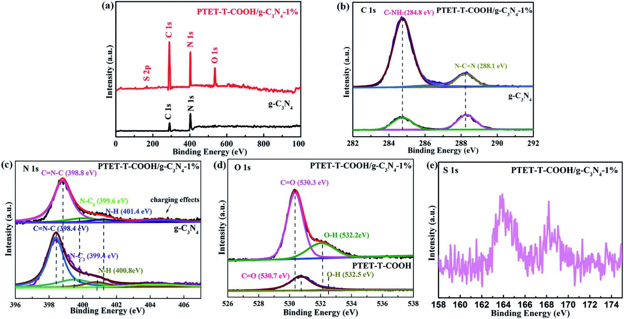 | ||
| Fig. 2 XPS spectra of pure g-C3N4 and PTET-T-COOH/g-C3N4-1% photocatalyst: (a) survey spectra, (b) C 1s, (c) N 1s, (d) O 1s and (e) S 2p. | ||
3.2 Morphology of as-prepared PTET-T-COOH/g-C3N4-1% photocatalyst
In Fig. 3a, it is found that pure g-C3N4 displays block microstructure. Meanwhile, from Fig. 3b it can be seen that pure PTET-T-COOH shows a flower-like microstructure which consists of plenty of thin nanosheets. The FESEM image of PTET-T-COOH/g-C3N4-1% heterostructure is shown in Fig. 3c. It can be clearly obtained that the g-C3N4 nanosheets are covered by PTET-T-COOH, forming a strong interface between PTET-T-COOH and g-C3N4. Additionally, this kind of strong interface is also further verified by the TEM image which is demonstrated in Fig. 3d. It can be directly seen that PTET-T-COOH nanosheets are tightly contacted to the surface of g-C3N4. Furthermore, in Fig. 4, EDS mapping of PTET-T-COOH/g-C3N4-1% photocatalyst confirms the existence of C, N, O and S in the whole selected area, revealing that all the elements are uniformly dispersed on the photocatalyst. According to the above discussion, it can be concluded that PTET-T-COOH/g-C3N4 photocatalyst is successfully fabricated. | ||
| Fig. 3 FESEM images of (a) g-C3N4, (b) PTET-T-COOH, (c) PTET-T-COOH/g-C3N4-1% and TEM image of (d) PTET-T-COOH/g-C3N4-1%. | ||
 | ||
| Fig. 4 EDS mapping of as-prepared PTET-T-COOH/g-C3N4-1% photocatalyst. | ||
3.3 UV-vis light adsorption of as-prepared photocatalyst
It is known to us that the band gap energy and light property of as-prepared photocatalyst are important. Therefore, the UV-vis DRS is tested and shown in Fig. 5. Depicted from Fig. 5a, pure g-C3N4 demonstrates poor visible light response whose light adsorption range is within 550 nm. However, pure PTET-T-COOH shows a wide light adsorption range which can be up to 700 nm. More interestingly, after loading PTET-T-COOH on g-C3N4 forming the heterostructure, the light adsorption range can be obviously extended to 600–700 nm, which is extremely beneficial to improving photocatalytic performance. Considering all the above mentioned, the band gap width of all the samples are calculated according to the formula: Ahυ = A(hυ − Eg)n/2, where A, Eg, α, hυ represent the light frequency, the band gap energy, the absorption coefficient and the Planck constant, respectively.43–45 According to the previous works and tested data, it can be concluded that the established Eg of the g-C3N4 is 2.32 eV, the Eg of the PTET-T-COOH is 1.76 eV and the Eg of the PTET-T-COOH/g-C3N4-1% is 1.75 eV, which is displayed in Fig. 5b. In order to study the specific conduction band (CB) and valence band (VB) position, the VB-XPS spectra of pure g-C3N4 and PTET-T-COOH are tested whose results are shown in Fig. 5c and d. Based on the VB-XPS spectra results and the calculated band gap energy, it can eventually concluded that the CB position of g-C3N4 is −0.52 eV and the CB position of PTET-T-COOH is −1.3 eV. | ||
| Fig. 5 (a) UV-vis DRS of as-prepared photocatalyst. (b) Plots of the (Ahυ)1/2 versus hυ for pure g-C3N4 and PTET-T-COOH/g-C3N4-1% photocatalyst. VB-XPS spectra of (c) pure g-C3N4 and (d) pure PTET-T-COOH. | ||
3.4 Photocatalytic performance
As is known to all, the high performance of synthesized photocatalyst is necessary. RhB, as a model contaminant, is chosen to measure the photocatalytic performance. As shown in Fig. 6a, it can be seen that the pure g-C3N4 and PTET-T-COOH show the poor photocatalytic performance whose degradation efficiency are only 7.19% and 42.3% within 120 min, respectively. However, when loading PTET-T-COOH on g-C3N4, the degradation efficiency is apparently enhanced. It can be noted that the optimal ratio of PTET-T-COOH/g-C3N4-1% photocatalyst shows an enhanced photocatalytic performance whose degradation efficiency can reach to approximately 90%. Meanwhile, the curves of the absorption change of RhB with as-prepared PTET-T-COOH/g-C3N4-1% photocatalyst are shown in Fig. 6b. It is obvious that the intensity of the UV-vis absorbance variations at 554 nm, which is consistent with RhB disappear gradually after degradation process. It reveals that the RhB molecules structures are effectively degraded and destructed. Additionally, the reaction kinetics of RhB is reported to accord with the kinetic equation of first-order reaction (Fig. 6c), ln(C0/C) = kt, in this formula, k are the apparent rate constants. It can be noticed in Fig. 6c that the rate constant of as-prepared PTET-T-COOH/g-C3N4-1% is 0.0184 min−1, which is higher than it in any other as-prepared samples. Based on the above mentioned, it can be deduced that the as-prepared PTET-T-COOH/g-C3N4-1% photocatalyst is considered as a highly efficient photocatalyst. | ||
| Fig. 6 (a) The degradation of pure g-C3N4, PTET-T-COOH and different ratios of PTET-T-COOH/g-C3N4 photocatalyst towards RhB. (b) Absorption spectra of RhB over the PTET-T-COOH/g-C3N4-1% photocatalyst. (c) The pseudo-first-order reaction kinetics over the as-prepared photocatalyst. | ||
3.5 The separation and transfer of charge carrier
It is well known to us that the light adsorption range and the separation and transfer of photogenerated carriers are important for a good photocatalyst to be applied in the photocatalytic reaction.46 Therefore, PL test, time-resolved fluorescence test and a series of electrochemical measurements are done in this research work in order to explore the efficiency of photogenerated carriers separation. As shown in Fig. 7a, pure g-C3N4 shows high fluorescence intensity, however, when coupled with PTET-T-COOH, the fluorescence intensity obviously reduced, suggesting that the recombination of electron–hole pairs is effectively restrained. Meanwhile, as displayed in Fig. 7b, time fluorescence spectra test also shows that the explicit lifetime of photogenerated carriers, which further confirms that the formation of PTET-T-COOH/g-C3N4-1% photocatalyst can contribute to the separation and diversion of photo-induced carriers. Additionally, electrochemical measurements are also carried out which is demonstrated in Fig. 7c and d. It can be clearly noted that the as-prepared PTET-T-COOH/g-C3N4-1% photocatalyst reveals a higher photocurrent response compared with it in pure g-C3N4. At the same time, the EIS Nyquist plots also show that the as-prepared PTET-T-COOH/g-C3N4-1% presents a smaller radius circle compared to it in pure g-C3N4, clarifying that the as-prepared PTET-T-COOH/g-C3N4-1% photocatalyst has a smaller interfacial charge transfer resistance. Based on the above discussion, it can be deduced that the as-prepared PTET-T-COOH/g-C3N4-1% photocatalyst is a high efficient and durable photocatalyst. | ||
| Fig. 7 (a) The PL spectra, (b) time-resolved fluorescence spectra, (c) transient photocurrent responses and (d) the EIS Nyquist plots of as-prepared pure g-C3N4 and PTET-T-COOH/g-C3N4-1%. | ||
As is well-known that the surface area (SBET) and specific pore structure of the as-prepared photocatalyst are important to the photocatalytic degradation efficiency. The tested BET results are shown in Fig. 8. It can be noted in Fig. 8 that the hysteresis loops of both the as-prepared g-C3N4 and PTET-T-COOH/g-C3N4-1% are regarded as the H3 type, which suggests that the as-prepared photocatalyst has mesopores, further providing the transfer route for the photogenerated electrons and holes. This kind of pores can faster separate of photogenerated carriers and improve the transfer of the charge carriers, thus enhancing the photocatalytic performance. Meanwhile, compared with the surface area in pure g-C3N4 (20.0768 m2 g−1), the as-prepared PTET-T-COOH/g-C3N4-1% photocatalyst has a larger surface area (38.9429 m2 g−1), suggesting that is probably ascribed to the large surface area which provides more active sites and absorption sites to enhanced photocatalytic performance.
 | ||
| Fig. 8 N2 adsorption–desorption isotherms of as-prepared g-C3N4 and PTET-T-COOH/g-C3N4-1% photocatalyst. | ||
Universally speaking, whether the photocatalytic reaction can succeed in proceeding depends on the generated active radicals such as ˙O2−, ˙OH radicals.47–49 Therefore, we test the photocatalytic degradation efficiency of the PTET-T-COOH/g-C3N4-1% photocatalyst with various scavengers under visible light irradiation which is demonstrated in Fig. 9a. The photocatalytic degradation efficiency showed visibly decreased when the scavenger BQ was added, suggesting that ˙O2− radical plays an crucial part in the photocatalytic reaction. Meanwhile, it can also be depicted that the photocatalytic degradation efficiency is slightly decreased in the presence of EDTA and IPA, respectively, which demonstrates that h+ and ˙OH radicals have a less impact on the photocatalytic reaction. In comparison with the photocatalytic degradation efficiency in the presence of various scavengers, we also test the photocatalytic degradation efficiency in the absence of scavengers, further confirming that the photogenerated active radicals have an important influence in the photocatalytic reaction. Furthermore, the electron spin resonance (ESR) spin-trap technique is tested which is shown in Fig. 9b and c. It is shown that the DMPO·O2− characteristic peaks are not found in the dark condition while they are discovered in the visible light irradiation, which implies that the ˙O2− radicals can be generated under visible light irradiation. At the same time, the DMPO·OH characteristic peaks are also detected in the as-prepared PTET-T-COOH/g-C3N4-1% photocatalyst. The ESR results are consistent with the radicals capture experiments (Fig. 9a), further providing direct evidence for the role of active radicals in the photocatalytic reaction.
 | ||
| Fig. 9 (a) Photocatalytic degradation efficiency of the as-prepared PTET-T-COOH/g-C3N4-1% photocatalyst for the degradation of RhB solution in the presence of various scavengers under visible light irradiation. ESR signals of the (b) DMPO·O2− and (c) DMPO·OH for as-prepared PTET-T-COOH/g-C3N4-1% photocatalyst both under dark and visible light irradiation. | ||
3.6 Stability tests
A good photocatalyst should not only have a high photocatalytic performance, but also a superior stability. Considering these two aspects, the cycling photocatalytic experiments of PTET-T-COOH/g-C3N4-1% for degradation of RhB are tested and provided in Fig. 10a. As shown in Fig. 10a, it can be noted that the degradation efficiency of RhB has no obvious change after four cycles, suggesting that the as-prepared PTET-T-COOH/g-C3N4-1% photocatalyst has a high stability. Additionally, XRD patterns of as-prepared PTET-T-COOH/g-C3N4-1% photocatalyst before and after photocatalytic reaction are also tested which is displayed in Fig. 10b. It can be depicted that the main XRD diffraction peaks have no evident change, indicating the basic structure of as-prepared photocatalyst is not changed, which further confirm the superior stability of as-prepared photocatalyst. Based on the above discussed, it can be concluded that the as-prepared PTET-T-COOH/g-C3N4-1% photocatalyst is a durable and high efficient photocatalyst. | ||
| Fig. 10 (a) Cycling photocatalytic experiments of PTET-T-COOH/g-C3N4-1% for degradation of RhB, (b) XRD patterns of as-prepared PTET-T-COOH/g-C3N4-1% photocatalyst before and after photocatalytic reaction. | ||
Considering the above results and discussions, the possible photocatalytic mechanism of as-prepared PTET-T-COOH/g-C3N4 heterostructure for degradation of RhB is displayed in Fig. 11. Both g-C3N4 and PTET-T-COOH can generate the photogenerated e−/h+ pairs under visible light irradiation. As shown in Fig. 11, it can be seen that the photoexcited electrons in the conduction band of PTET-T-COOH can transfer to the conduction band of g-C3N4, while the photogenerated holes will transfer from the VB of g-C3N4 to the VB of PTET-T-COOH. These photogenerated carriers are following this transfer path which is beneficial to the separation of photogenerated e−/h+ pairs as well as prohibit the recombination of them, thus enhancing the photocatalytic performance. The accumulated photogenerated electrons on the conduction band of g-C3N4 can be captured O2 by the reduction to form ˙O2− radicals thanks to its more negative potential (ECB, −0.53 eV vs. NHE).50,51 The model organic contaminant RhB can be oxidized and discomposed by the strong oxidation of formed ˙O2− radicals. Meantime, the photogenerated holes on the VB of PTET-T-COOH cannot directly produce ˙OH radicals due to its more negative potential (EVB, 0.5 eV vs. NHE).52–54 However, the active radical capture experiments show that the ˙OH radicals have an influence on the photocatalytic performance which is corresponding with the ESR results. The ˙OH radicals are detected by the ERS technique. Thence, there is no doubt that the ˙OH radicals are generated by the oxidation of H2O2. The H2O2 is produced by the reaction H2O2 (O2 + 2e− + 2H+ = H2O2 (aq)) whose potential is O2/H2O2 = 0.682 eV.1 According to this proposed pathway, the as-prepared PTET-T-COOH/g-C3N4 heterostructure shows the improved separation and transferability of photogenerated electron–hole pairs, thus enhancing the photocatalytic degradation of RhB.
 | ||
| Fig. 11 The photocatalytic mechanism of as-prepared PTET-T-COOH/g-C3N4 heterostructure for degradation of RhB under visible light irradiation. | ||
4. Conclusions
To sum up, we successfully synthesized the PTET-T-COOH/g-C3N4 heterostructure via a simple method. The synthesized PTET-T-COOH/g-C3N4 heterostructure displays the enhanced photocatalytic degradation ability towards the model organic contaminant RhB. Meantime, the photocatalytic degradation rate constant is nearly 3.83 times than that of the onefold g-C3N4. The preferable photocatalytic degradation efficiency is mainly ascribed to three aspects. One is the faster photogenerated carriers transferability and lower photogenerated electron–hole pairs recombination because of the formation of PTET-T-COOH/g-C3N4 heterostructure. The second is more active sites and reaction sites can be provided by the larger surface area. The third is the strong interaction between PTET-T-COOH and g-C3N4. In addition, the as-prepared PTET-T-COOH/g-C3N4 heterostructure may provide new promising approaches of fabricating any other heterostructures with high photocatalytic activity and superior stability.Conflicts of interest
There are no conflicts to declare.Acknowledgements
This work was supported by the Natural Science Foundation of China (Grant No. 51603086 and 21576112), the Natural Science Foundation of Jilin Province (Grant No. 20160520131JH, 20180101181JC and 20180623042TC), the Project of Human Resources and Social Security Department of Jilin Province (2017956), the Project of Jilin Province Development and Reform Commission (2019C044) and the Science and Technology Research Project of the Department of Education of Jilin Province (2016-218, JJKH20180791KJ, 20190303069SF), the Postgraduate Innovative Research Program of Jilin Normal University (201918)References
- X. W. Ruan, H. Hu, H. N. Che, G. B. Che, C. M. Li, C. B. Liu and H. J. Dong, J. Alloys Compd., 2019, 773, 1089–1098 CrossRef CAS.
- C. Li, G. Chen, J. Sun, J. Rao, Z. Han, Y. Hu, W. Xing and C. Zhang, Appl. Catal., B, 2016, 188, 39–47 CrossRef CAS.
- C. Li, G. Chen, J. Sun, J. Rao, Z. Han, Y. Hu, W. Xing and C. Zhang, Appl. Catal., B, 2016, 188, 39–47 CrossRef CAS.
- C. M. Li, S. Y. Yu, L. Gu, J. Han, H. J. Dong, Y. Wang and G. Chen, Adv. Mater. Interfaces, 2018, 1801297 CrossRef.
- X. W. Ruan, H. Hu, H. N. Che, E. H. Jiang, X. X. Zhang, C. B. Liu and G. B. Che, J. Colloid Interface Sci., 2019, 543, 317–327 CrossRef CAS PubMed.
- X. W. Ruan, H. Hu, G. B. Che, P. J. Zhou, C. B. Liu and H. J. Dong, J. Colloid Interface Sci., 2019, 553, 186–196 CrossRef CAS PubMed.
- H. N. Che, G. B. Che, H. J. Dong, W. Hu, H. Hu, C. B. Liu and C. M. Li, Appl. Surf. Sci., 2018, 445, 705–716 CrossRef.
- R. R. Jiang, G. H. Lu, D. H. Wu, Z. H. Yan, R. R. Zhou and X. H. Bao, Chem. Eng. J., 2019, 374, 79–90 CrossRef CAS.
- H. N. Che, J. B. Chen, K. Huang, W. Hu, H. Hu, X. T. Liu, G. B. Che, C. B. Liu and W. D. Shi, J. Alloys Compd., 2016, 688, 882–890 CrossRef CAS.
- J. B. Chen, H. N. Che, K. Huang, C. B. Liu and W. D. Shi, Appl. Catal., B, 2016, 192, 134–144 CrossRef CAS.
- Y. X. Liu, H. X. Dai, J. G. Deng, L. Zhang and C. T. Au, Nanoscale, 2012, 4, 2317–2325 RSC.
- K. F. Zhang, Y. X. Liu, J. G. Deng, S. H. Xie, H. X. Lin and X. T. Zhao, et al., Appl. Catal., B, 2017, 202, 569–579 CrossRef CAS.
- C. M. Li, Y. Xu, W. G. Tu, G. Chen and R. Xu, Green Chem., 2017, 19, 882–899 RSC.
- I. T. Carvalho and L. Santos, Environ. Int., 2016, 94, 736–757 CrossRef PubMed.
- M. O. Barbosa, N. F. F. Moreira, A. R. Ribeiro and M. F. R. Pereira, Water Res., 2016, 94, 257–279 CrossRef CAS PubMed.
- C. C. Chen, W. H. Ma and J. C. Zhao, Chem. Soc. Rev., 2010, 39, 4206–4219 RSC.
- X. Zhu, J. Zhang and F. Chen, Appl. Catal., B, 2011, 102, 316–322 CrossRef CAS.
- Y. R. Lv, R. Huo, S. Y. Yang, Y. Q. Liu, X. J. Li and Y. H. Xu, Sep. Purif. Technol., 2018, 197, 281–288 CrossRef CAS.
- N. C. S. Selvam, Y. G. Kim, D. J. Kim, W. H. Hong, W. Kim and S. H. Park, et al., Sci. Total Environ., 2018, 635, 741–749 CrossRef PubMed.
- W. J. Ong, L. L. Tan, Y. H. Ng, S. T. Yong and S. P. Chai, Chem. Rev., 2016, 116, 7159–7329 CrossRef CAS PubMed.
- Z. G. Xiong, J. Z. Ma, W. J. Ng, T. D. Waite and X. S. Zhao, Water Res., 2011, 45, 2095–2103 CrossRef CAS PubMed.
- M. M. Mahlambi, C. J. Ngila and B. B. Mamba, J. Nanomater., 2015, 1–29 Search PubMed.
- F. Davar, A. Majedi and A. Mirzaei, J. Am. Ceram. Soc., 2015, 98, 1739–1746 CrossRef CAS.
- S. Ren, F. Besenbacher and G. Hutchings, Alternative Materials to TiO2, in Heterogeneous Photocatalysis Green Chemistry and Sustainable Technology, ed. J. Colmenares and Y. J. Xu, Springer, Berlin, Heidelberg, 2016, pp. 109–149 Search PubMed.
- Y. Wang, L. X. Liu, L. Xu, X. X. Cao, X. H. Li, Y. J. Huang, C. M. Meng, Z. G. Wang and W. J. Zhu, RSC Adv., 2014, 6, 6790–6797 CAS.
- Z. Xiong, Z. Lei, C. C. Kuang, X. X. Chen, B. G. Gong, Y. C. Zhao, J. Y. Zhang, C. G. Zheng and J. C. S. Wu, Appl. Catal., B, 2017, 202, 695–703 CrossRef CAS.
- T. M. Di, B. C. Zhu, B. Cheng, J. G. Yu and J. S. Xu, J. Catal., 2017, 352, 532–541 CrossRef CAS.
- J. Fu, B. Zhu, C. Jiang, B. Cheng, W. You and J. Yu, Small, 2017, 13, 1603938 CrossRef PubMed.
- J. Li, M. Zhang, Q. Y. Li and J. J. Yang, Appl. Surf. Sci., 2017, 391, 184–193 CrossRef CAS.
- L. F. Cui, X. Ding, Y. G. Wang, H. C. Shi, L. H. Huang, Y. H. Zuo and S. F. Kang, Appl. Surf. Sci., 2017, 391, 202–210 CrossRef CAS.
- Z. Wan, G. K. Zhang, X. Y. Wu and S. Yin, Appl. Catal., B, 2017, 207, 17–26 CrossRef CAS.
- J. Li, E. Z. Liu, Y. N. Ma, X. Y. Hu, J. Wan, L. Sun and J. Fan, Appl. Surf. Sci., 2016, 364, 694–702 CrossRef CAS.
- Y. Y. Shang, X. Chen, W. W. Liu, P. F. Tan, H. Y. Chen, L. D. Wu, C. Ma, X. Xiong and J. Pan, Appl. Catal., B, 2017, 204, 78–88 CrossRef CAS.
- L. Zhou, W. Zhang, L. Chen and H. P. Deng, J. Colloid Interface Sci., 2017, 487, 410–417 CrossRef CAS PubMed.
- Z. Zhu, P. W. Huo, Z. Y. Lu, Y. S. Yan, Z. Liu, W. D. Shi, C. X. Li and H. J. Dong, Chem. Eng. J., 2018, 331, 615–625 CrossRef CAS.
- G. Q. Tan, L. N. She, T. Liu, C. Xu, H. J. Ren and A. Xia, Appl. Catal., B, 2017, 207, 120–133 CrossRef CAS.
- Y. J. Zhang, D. K. Zhang, W. M. Guo and S. J. Chen, J. Alloys Compd., 2016, 685, 84–90 CrossRef CAS.
- S. K. Le, T. S. Jiang, Y. W. Li, Q. Zhao, Y. Y. Li, W. B. Fang and M. Gong, Appl. Catal., B, 2017, 200, 601–610 CrossRef CAS.
- C. K. Fan, Q. Feng, G. Q. Xu, J. Lv, Y. Zhang, J. Q. Liu, Y. Q. Qin and Y. C. Wu, Appl. Surf. Sci., 2018, 427, 730–738 CrossRef CAS.
- Y. C. Wang, J. Zhou, X. Q. Hao, Y. Wang and Z. G. Zou, Appl. Surf. Sci., 2018, 456, 861–870 CrossRef CAS.
- G. Y. Zhuge and W. D. Zhang, Chemcatchem, 2018, 11(3), 1045–1056 Search PubMed.
- L. B. Jiang, X. Z. Yuan, G. G. Zeng, X. H. Chen, Z. B. Wu, J. Liang, J. Zhang, H. Wang and H. Wang, ACS Sustainable Chem. Eng., 2017, 5, 5831–5841 CrossRef CAS.
- H. N. Che, L. H. Liu, G. B. Che, H. J. Dong, C. B. Liu and C. M. Li, Chem. Eng. J., 2019, 357, 209–219 CrossRef CAS.
- R. R. Jiang, D. H. Wu, G. H. Lu, Z. H. Yan, J. C. Liu, R. R. Zhou and M. Nkoom, J. Taiwan Inst. Chem. Eng., 2019, 96, 681–690 CrossRef CAS.
- Y. Guo, P. F. Wang, J. Qian, Y. H. Ao, C. Wang and J. Hou, Appl. Catal., B, 2018, 234, 90–99 CrossRef CAS.
- S. Gong, Z. Jiang, P. Shi, J. Fan, Q. Xu and Y. Min, Appl. Catal., B, 2018, 238, 318–327 CrossRef CAS.
- W. X. Zou, Y. Shao, Y. Pu, Y. D. Luo, J. F. Sun, K. L. Ma, C. J. Tang, F. Gao and L. Dong, Appl. Catal., B, 2017, 218, 51–59 CrossRef CAS.
- P. Mohammadyari and A. Nezamzadeh-Ejhieh, RSC Adv., 2015, 5, 75300–75310 RSC.
- X. Zhao, Z. Lu, M. Wei, M. Zhang, H. Dong, C. Yi, R. Ji and Y. Yan, Appl. Catal., B, 2018, 220, 137–147 CrossRef CAS.
- M. L. Ren, J. Chen, P. F. Wang, J. Hou, J. Qian, C. Wang and Y. H. Ao, J. Colloid Interface Sci., 2018, 532, 190–200 CrossRef CAS PubMed.
- B. B. Shao, X. J. Liu, Z. F. Liu, G. G. Zeng, Q. H. Liang, C. Liang, Y. Cheng, W. Zhang, Y. Liu and S. X. Gong, Chem. Eng. J., 2019, 368, 730–745 CrossRef CAS.
- X. Zhang, R. Li, M. Jia, S. Wang, Y. Huang and C. Chen, Chem. Eng. J., 2015, 274, 290–297 CrossRef CAS.
- S. J. Li, J. L. Chen, Y. P. Liu, K. B. Xu and J. S. Liu, J. Alloys Compd., 2019, 781, 582–588 CrossRef CAS.
- C. X. Li, H. N. Che, C. B. Liu, G. B. Che, P. A. Charpentier, W. Z. Xu, X. Y. Wang and L. H. Liu, J. Taiwan Inst. Chem. Eng., 2019, 95, 669–681 CrossRef CAS.
| This journal is © The Royal Society of Chemistry 2020 |