
 Open Access Article
 This Open Access Article is licensed under a Creative Commons Attribution-Non Commercial 3.0 Unported Licence
Stability of 2H- and 1T-MoS2 in the presence of aqueous oxidants and its protection by a carbon shell
Randal Marksa,
Andrew Schrancka,
Roy Stillwellb and
Kyle Doudrick *a
*a
aUniversity of Notre Dame, Department of Civil and Environmental Engineering and Earth Sciences, 156 Fitzpatrick Hall, Notre Dame, Indiana 46556, USA. E-mail: kdoudrick@nd.edu; Tel: +1-574-631-0305
bUniversity of Notre Dame, Department of Electrical Engineering, USA
First published on 4th March 2020
Abstract
Two-dimensional molybdenum disulfide (MoS2) is emerging as a catalyst for energy and environmental applications. Recent studies have suggested the stability of MoS2 is questionable when exposed to oxidizing conditions found in water and air. In this study, the aqueous stability of 2H- and 1T-MoS2 and 2H-MoS2 protected with a carbon shell was evaluated in the presence of model oxidants (O2, NO2−, BrO3−). The MoS2 electrocatalytic performance and stability was characterized using linear sweep voltammetry and chronoamperometry. In the presence of dissolved oxygen (DO) only, 2H- and 1T-MoS2 were relatively stable, with SO42− formation of only 2.5% and 3.1%, respectively. The presence of NO2− resulted in drastically different results, with SO42− formations of 11% and 14% for 2H- and 1T-MoS2, respectively. When NO2− was present without DO, the 2H- and 1T-MoS2 remained relatively stable with SO42− formations of only 4.2% and 3.3%, respectively. Similar results were observed when BrO3− was used as an oxidant. Collectively, these results indicate that the oxidation of 2H- and 1T-MoS2 can be severe in the presence of these aqueous oxidants but that DO is also required. To investigate the ability of a capping agent to protect the MoS2 from oxidation, a carbon shell was added to 2H–MoS2. In a batch suspension in the presence of DO and NO2−, the 2H–MoS2 with the carbon shell exhibited good stability with no oxidation observed. The activity of 2H–MoS2 electrodes was then evaluated for the hydrogen evolution reaction by a Tafel analysis. The carbon shell improved the activity of 2H–MoS2 with a decrease in the Tafel slope from 451 to 371 mV dec−1. The electrode stability, characterized by chronopotentiometry, was also enhanced for the 2H–MoS2 coated with a carbon shell, with no marked degradation in current density observed over the reaction period. Because of the instability exhibited by unprotected MoS2, it will only be a useful catalyst if measures are taken to protect the surface from oxidation. Further, given the propensity of MoS2 to undergo oxidation in aqueous solutions, caution should be used when describing it as a true catalyst for reduction reactions (e.g., H2 evolution), unless proven otherwise.
1. Introduction
Two-dimensional molybdenum disulfide (2D MoS2) is a nanomaterial that has been extensively investigated for a wide variety of chemical and physical applications due to its unique chemical and physical properties.1–5 Of the three crystalline phases (3R, 2H, and 1T), 2H–MoS2 is the most thermodynamically stable structure and has been the most widely studied for chemical functions. 2H–MoS2 is a planar structure consisting of sheets of S–Mo–S that are held together by weak Van der Waals forces, maintaining a trigonal geometry. The typical depth of one layer is approximately 0.7 nm.6 Applications of MoS2 include, but are not limited to, photocatalysis due to its solar active band gap of approximately 1.2–1.7 eV,7–9 catalytic reduction of contaminants,10 hydrodesulfurization (HDS) catalysis of sulfur containing compounds in petroleum products,11–14 and electrocatalysis of water for the production of hydrogen gas.15–19The electrocatalytic ability of MoS2 to generate H2 was discovered in the 1970's.20 More recently, 2H–MoS2 nanoparticles were proposed as an effective hydrogen evolution reaction (HER) electrocatalyst based on first-principles calculations that suggested hydrogen binding at Mo–S sites was nearly thermoneutral.21 The Mo (1010) disulfide (S22−) and sulfide (S2−) edge sites of 2H–MoS2 were demonstrated to be highly active for the HER.22 These groundbreaking studies set the stage for a meaningful effort on optimization of the 2H–MoS2 nanoparticles for the HER reaction.6,23–26 Challenges to deployment of 2H–MoS2 that have been investigated include increasing the active sites per unit volume,23,27–30 tuning the activity of the catalyst to promote HER by adjusting ΔGsorp towards zero,31–34 and improving the electron transfer kinetics of the catalyst.7,24,35,36
1T-MoS2, a metastable metallic crystalline phase, has been known since at least the 1970's,37,38 but it was not seriously investigated as a catalytic material until recently because of its challenging synthesis procedure. Typical synthesis involves the exfoliation of single layer 1T-MoS2 layers from 2H–MoS2 stacks using aggressive reagents such as tert-butyl lithium, making the technique challenging for wider study.39 Hydrothermal intercalation of ammonium is a promising alternative synthesis method for 1T-MoS2, where high temperature and pressure is used to drive ammonium ions between MoS2 sheets and exfoliate 1T-MoS2.40,41 1T-MoS2 has an octahedral symmetry rather than the trigonal symmetry of 2H–MoS2, giving it a metallic band structure that is critical for overcoming electron transfer limitations for electrocatalysis.28 Further, the octahedral crystal structure shifts the ΔGH of the basal plane sites to near zero, allowing for their participation in the HER reaction and greatly increasing the active site density on the catalyst.42 Due to these properties, 1T-MoS2 is a more attractive catalyst for the HER than 2H–MoS2.28
Greater interest in using 2D MoS2 for environmental applications has recently emerged. Because of the tunable nature of its physical and chemical properties from changing nanoparticle size, layering, and crystallinity, 2D MoS2 has been studied as an adsorbent of heavy metals,43,44 a photocatalyst for various contaminants,45,46 a membrane separation material,47,48 an antibacterial agent,49,50 and a sensor for contaminants.51 However, thus far, there has been little comprehensive investigation of the stability of MoS2 under realistic environmental conditions. Other metal sulfides (e.g., ZnS52 and FeS2![[thin space (1/6-em)]](https://www.rsc.org/images/entities/char_2009.gif) 53) are known to be unstable under oxidizing conditions, so the evaluation of the MoS2 stability under relevant conditions is critical. Under more realistic environmental aqueous conditions, the presence of oxygen was shown to cause oxidation of 2D MoS2.54,55 Wang et al. demonstrated that 2D MoS2 oxidizes under aerated aqueous conditions, according to eqn (1):55
53) are known to be unstable under oxidizing conditions, so the evaluation of the MoS2 stability under relevant conditions is critical. Under more realistic environmental aqueous conditions, the presence of oxygen was shown to cause oxidation of 2D MoS2.54,55 Wang et al. demonstrated that 2D MoS2 oxidizes under aerated aqueous conditions, according to eqn (1):55
 | (1) |
In the study by Wang et al., dissolution occurred for both 2H- and 1T-MoS2 with half-lives of approximately 1–30 days, but the dissolution rate was faster for 1T-MoS2, due to its larger number of reactive edge sites. This behavior was supported by Lee et al.,54 showing that the oxidation of 2D MoS2 was slowed in the presence of natural organic matter, but that the presence of sunlight and dissolved organic carbon could enhance the oxidation. Despite these results, the dissolution or stability of 2D MoS2 with regards to environmental applications has not been fully addressed.
The primary objectives of this study were to investigate the effect of oxidants present in natural waters on the short-term stability of 1T- and 2H–MoS2 nanoparticles, and to evaluate the use of a graphitic carbon coating shell as a method for protecting MoS2 from oxidation. Carbon shells have been shown to increase the stability of MoS2 for various applications.56,57 Nitrite and bromate were chosen as model oxidants because of their relative ease of reduction as opposed to those with higher activation energies (e.g., nitrate, perchlorate). The MoS2 stability was characterized by measuring the reduction of nitrite or bromate concentrations and the formation of sulfate, a byproduct of MoS2 oxidation. The electrocatalytic performance and stability of MoS2 for the HER were investigated using linear sweep voltammetry and chronoamperometry, respectively. The outcomes are beneficial to identifying the feasibility of using 1T- and 2H–MoS2 for aqueous applications involving oxidizing conditions.
2. Methods and materials
2.1 Synthesis of MoS2 nanoparticles
Commercial MoS2 nanoparticles (C–MoS2) were purchased (Sigma-Aldrich, 804169) to be used as a comparison to the lab-synthesized MoS2 nanoparticles. 2H–MoS2 nanoparticles were synthesized by hydrothermal methods adapted from literature.58 2H–MoS2 was synthesized by first dissolving 0.740 g of Na2MoO4 (Alfa Aesar, 12214) in 36 mL of ultrapure water. Then, 254 μL of thioacetic acid (VWR, AAAL03305) was then added to this solution and stirred for 10 minutes. Finally, the solution was transferred to a 125 mL Teflon lined hydrothermal reactor (Parr 4748) and heated to 200 °C for 24 hours. The sample temperature was cooled naturally to 25 °C, then centrifugally washed with water three times followed by a single ethanol wash. The resulting black pellet was dried to a powder at 50 °C in air. The powder was then ground with a mortar and pestle prior to use. 1T-MoS2 was synthesized using adapted method similar to a previous study.40 First, 1.164 g of (NH4)6Mo7O24 (Fisher Scientific, S25171) was dissolved in 62.5 mL of ultrapure water. Then 1.148 g of thiourea (VWR, A12828) was added to the solution and stirred for 10 minutes. The solution was then transferred to a 125 mL hydrothermal reactor and heated to 200 °C for 24 hours prior to washing and drying as described previously for 2H–MoS2.2.2 Carbon coating of MoS2 nanoparticles
The MoS2 was coated with an ultrathin layer of carbon using previously described methods.59 0.3 g of the synthesized 2H–MoS2 nanoparticles were suspended in 80 mL of a 10 mM TRIS buffer (VWR, J831). Then, 0.1, 2.0, or 3.0 g L−1 of dopamine chloride (Alfa Aesar, A11136) was added to slurry and bath sonicated for 1 hour, during which time dopamine attached to the MoS2. Coated particles were centrifuged, washed with ultrapure water, and then air-dried at 50 °C. The resulting brown powder was pyrolyzed at 700 °C for 2 hours in a tube furnace with N2 flow, causing the powder to turn black as dopamine was carbonized.2.3 Aqueous stability testing in the presence of nitrite or bromate
The MoS2 stability in the presence of nitrite (NO2−) or bromate (BrO3−) was tested by tracking the reduction of nitrite or bromate and the formation of sulfate over time. All experiments were conducted in a 50 mL batch reactor. All experiments contained approximately 1 g L−1 of MoS2 and NO2− or BrO3− at varying concentrations. The pH of all samples ranged from approximately 6.0 to 6.3, depending on the concentrations of NO2− and BrO3− used. Gas bubbling (H2 or N2) was performed by flowing the gas through a glass diffuser into the solution at a flow rate of 150 mL min−1 to ensure saturation. The total reaction time was 6 h. 1 mL samples were taken at regular intervals and syringe filtered through a 0.45 μm nylon membrane. Samples were subsequently analyzed for concentrations of nitrite, nitrate (NO3−), BrO3−, bromide (Br−), and sulfate (SO42−) by ion chromatography (IC; Dionex ICS 5000+). Unknown peaks attributed to molybdate species were also detected at late elution times in the IC chromatographs, but they were not quantified due to a lack of available standards. All experiments were conducted as single experiments, thus any rates or percent removals or formation cannot be considered absolute. Instead, values are used to report general observations and comparisons.2.4 Characterization techniques
Images of the MoS2 materials were collected using a high-resolution transmission electron microscope (TEM; Titan 80–300). Samples were prepped by drop-casting ethanolic suspensions of the MoS2 on lacey carbon copper grids. Raman spectra were collected on a Jasco NRS 5100 Micro-Raman spectrometer. The crystal structure was investigated with powder X-ray diffraction (Cu Kα, 0.15418 nm; Bruker D8 Advance Davinci). The theoretical carbon shell thickness of coated MoS2 was estimated assuming spherical MoS2 particles and complete attachment and conversion of dopamine to pure carbon.2.5 Electrochemical characterization of MoS2 electrodes
MoS2 electrodes were created by drop casting MoS2 suspensions onto carbon paper substrates. Carbon paper (Toray, 5% wetproof) was cut into 1.5 cm × 5.0 cm sheets and placed on an aluminum foil covered hot plate set to 175 °C. 20 mg of MoS2 were suspended in 10 mL of ultrapure water and 62.5 μL of 20% Nafion (Ion Power, D-2020-US-25) was added to the suspension and then bath sonicated for 1 h. Then, 500 μL of the resulting suspension was drop cast onto the hot carbon paper electrode and then dried.To perform the electrochemical characterization, a three-electrode system was used in an undivided reactor consisting of a Pt wire as the counter electrode, a standard calomel electrode (SCE) as the reference electrode, and the MoS2 coated carbon paper electrodes as the working electrode. A Biologic SP200 potentiostat (BioLogic USA) with EC Lab software was used to administer linear sweep voltammetry (LSV) and chronoamperometry (CA) experiments. For LSV, an electrolyte containing only 1 N H2SO4 was used to probe the HER. Prior to analysis, the reactor was bubbled with N2 for 20 minutes to flush O2. LSV was conducted at a rate of 5 mV s−1 from 0.3 to −0.4 V vs. SCE. LSV was repeated three times and potentials adjusted by −0.242 V to correct to the Reversible Hydrogen Electrode (RHE). Tafel plots and slopes where obtained from the linear portion of the η vs. log|I| taken from the LSV. CA experiments were conducted at −0.5 V vs. SCE for 60 minutes in a solution containing an inert supporting electrolyte, 1 N NaClO4, to reduce solution resistance. Experiments were repeated with the addition of 7.14 mM NaNO2 (100 mg-N/L NO2−) to evaluate the stability of the MoS2 electrodes in the presence of NO2−. All experiments were conducted as single experiments, thus the Tafel slopes and current densities reported cannot be considered to be absolute. Instead, values are used to report general observations and comparisons.
3. Results and discussion
3.1 Materials characterization
Fig. 1 shows TEM images of the 2H–MoS2 and C–MoS2 nanoparticles. The size and shape differences of the two are obvious, with the 2H–MoS2 consisting of particles/sheets less than 100 nm in diameter (Fig. 1A) and the C–MoS2 (Fig. 1B) consisting of comparatively larger flake-like particles that approach micrometer scale dimensions. HR-TEM (Fig. 1A inset) confirmed the well-organized crystal structure of the 2H–MoS2 particles. The MoS2 particles were further characterized by pXRD (Fig. 1C) and Raman spectroscopy (Fig. 1D). The XRD diffraction patterns confirmed the 2H crystalline phase for the 2H- and C–MoS2 particles, while the 1T-MoS2 sample had similar but shifted peaks indicative of the 1T crystalline phase. The resolution of the diffraction pattern for the 2H–MoS2 particles was poor, despite using a long dwell time at each 2θ (>2 s). While poor resolution often indicates low crystallinity, peak broadening and low resolution are consistent with nano-sized MoS2,40,58 and the behavior may be attributed to the poor interaction of the single or few layer MoS2 with the X-ray beam. Raman spectroscopy was used to confirm the crystal structure. The red dotted vertical lines in the Raman spectra correspond to the E1g (280 cm−1), 1E2g (375 cm−1), and A1g (404 cm−1) vibrations of the 2H crystalline phase,60 while peaks at 156, 225, 235, and 333 cm−1 are generated by 1T phases marked by the green dashed lines.40 The spectra of C–MoS2 and 2H–MoS2 showed only characteristic peaks of the 2H crystalline phase, while the 1T-MoS2 spectrum showed characteristic peaks of both 2H and 1T crystalline phases. The nature of the characterized MoS2 species can be summarized as follows: 1T-MoS2 consists of a mixture of single layer 1T and 2H few layer nanoparticles, the 2H–MoS2 consists of few-layer 2H nanoparticles, and the C–MoS2 is the 2H phase and consists of many stacked layers forming larger particles. | ||
| Fig. 1 TEM images of (A) 2H–MoS2 and (B) C–MoS2 nanoparticles showing difference in particle sizes and crystallinity, (C) pXRD diffractogram of MoS2 materials, (D) Raman spectra of MoS2 species; red dotted lines indicate 2H crystallinity and green dashed lines indicate 1T crystallinity. | ||
3.2 Aqueous stability in water containing dissolved oxygen
The short-term aqueous stability of the MoS2 materials was evaluated in water containing only dissolved oxygen (DO), which was approximately 0.26 mM at conditions tested. The oxidation of MoS2 was measured by tracking the byproduct SO42−, reported as a percent of the total available S in the system (Fig. 2). For each MOS2 sample, an immediate increase in SO42− upon exposure to water was observed, which is presumably due to the rapid oxidation of the surface MoS2 into MoxOyn− species (i.e., eqn (1)). Differences in SO42− release may be attributed to the reactivity of the surface sites, and to some degree, the surface area of available sites. After the initial period, the SO42− concentration stabilized for 1T- and C–MoS2 and increased only slightly for 2H–MoS2 over the time-period tested. The total oxidation of MoS2, reported as the percentage of total sulfur in the system converted to SO42−, was 0.63%, 2.5%, and 3.1% for C–MoS2, 2H–MoS2, and 1T-MoS2, respectively (Table 1). Overall, the MoS2 materials were relatively stable over the 4 hour measurement period. These results agree with the comparatively long reported half-lives of 2H- and 1T-MoS2 stability in aqueous solution of up to 30 days.52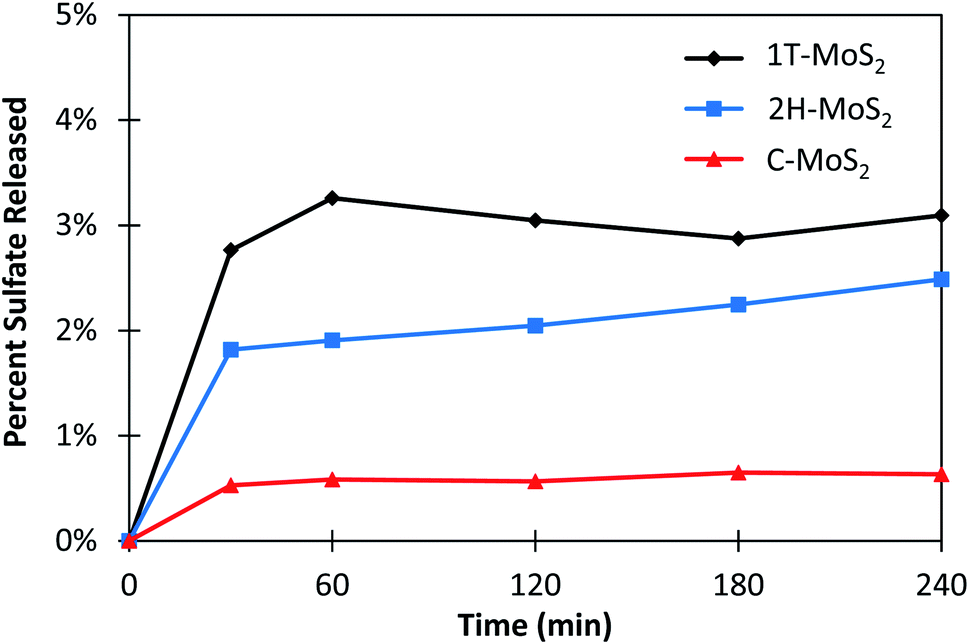 | ||
| Fig. 2 Dissolution of sulfate measured as a percent of the total available sulfur in solution. 1 g L−1 of MoS2 was used in each experiment. | ||
| MoS2 sample | Condition | Initial NO2− concentration (mM) | NO2− or BrO3− removal (%) | NO2− or Br−selectivity (%) | SO42−% formation (of total available S) |
|---|---|---|---|---|---|
| C–MoS2 | DO | 0 | — | — | 0.63% |
| C–MoS2 | DO, NO2− | 3.57 | 9.4% | 0% | 0.54% |
| C–MoS2 | H2, NO2− | 3.57 | 16% | 0% | 0.44% |
| 2H–MoS2 | DO | 0 | — | — | 2.5% |
| 2H–MoS2 | DO, NO2− | 3.57 | 100% | 7.4% | 11% |
| 2H–MoS2 | H2, NO2− | 3.57 | 88% | 2.0% | 4.2% |
| 2H–MoS2 | DO, NO2− (high) | 35.7 | 46% | 16% | 29% |
| 2H–MoS2 | H2, NO2− (high) | 35.7 | 2% | 1% | 5% |
| 1T-MoS2 | DO | 0 | — | — | 3.1% |
| 1T-MoS2 | DO, NO2− | 3.57 | 100% | 8.3% | 14% |
| 1T-MoS2 | H2, NO2− | 3.57 | 84% | 3.2% | 3.3% |
| 1T-MoS2 | DO, BrO3− | 0.75 | 60% | 61% | 3.5% |
| 1T-MoS2 | H2, BrO3− | 0.75 | 21% | 68% | 1.0% |
3.3 Effect of nitrite and bromate on MoS2 stability
The stability of MoS2 was tested against NO2− and BrO3− as aqueous oxidants because they are known to be easily reduced in the presence of suitable reductants.61–64 These experiments also served to probe the importance of the presence of DO compared to other oxidants. Fig. 3 shows the kinetic results for the reduction of NO2− and the subsequent formation of NO3− and SO42− in the presence of C-, 2H-, and 1T-MoS2. The results are summarized in Table 1. Experiments were conducted in the presence of DO and then repeated under H2 saturated conditions. For C–MoS2 in the presence of DO (Fig. 3A), NO2− was initially removed but reached a steady-state of 9.5% removal after 2 h. SO42− was formed in conjunction with NO2− removal, reaching a steady-state value of only 0.55% of the total available S, which was similar to conditions without NO2− (i.e., Fig. 2). Thus, NO2− did not have a major impact on C–MoS2 oxidation, and the observed NO2− removal can be presumably attributed to adsorption of NO2− to C–MoS2 or to surface oxidation of C–MoS2. For the 2H- and 1T-MoS2 samples in the presence of DO (Fig. 3B and C), NO2− was completely removed within 3 h and 1 h, respectively. The formation of SO42− increased to 11.5% and 13.5% of the total available S for 2H–MoS2 and 1T-MoS2, respectively, indicating the MoS2 oxidation increased compared to conditions without NO2− (i.e., Fig. 2). NO3− formation was also observed for 2H–MoS2 and 1T-MoS2 experiments, with a selectivity of 7.7% and 8.3% of the initial N, respectively. NO3− is a byproduct of NO2− oxidation, which is somewhat unexpected considering the oxidation of MoS2 would result in NO2− reduction. After the reaction was complete, the 2H- and 1T-MoS2 samples exhibited a bluish color, indicating the formation of Mo(V) species.65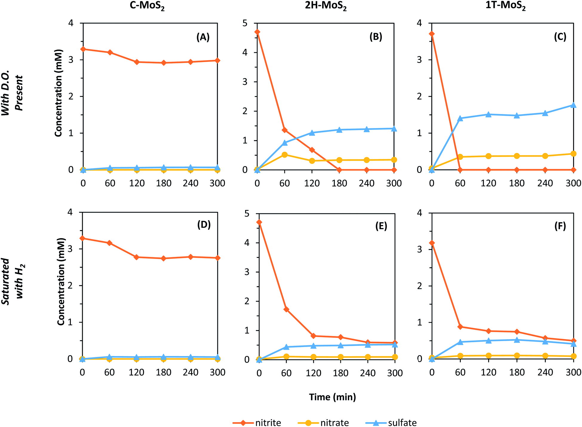 | ||
| Fig. 3 Loss of NO2− and formation of NO3− and SO42− in the presence of MoS2 materials. (A–C) are samples with dissolved O2 and (D–F) are samples that were saturated with H2; (A and D) C–MoS2, (B and E) 2H–MoS2, and (C and F) 1T-MoS2. The initial target NO2− concentration was approximately 3.5–4.5 mM in all experiments and the MoS2 concentration was 1 g L−1. | ||
MoS2 could potentially be acting as a hydrogenation catalyst (i.e., H2 dissociation) and DO may play an intermediate role in the reaction. Thus, to investigate these effects, experiments were repeated with H2 saturated water with limited DO (Fig. 3D–F). For C–MoS2, similar results were observed compared to the experiment with DO, suggesting no specific mechanism related to DO or H2. The 2H- and 1T-MoS2 materials showed more response to the exclusion of DO and presence of H2, with smaller changes in NO2−, SO42−, and NO3− concentrations observed (Table 1). Again, the NO2− removal was initially rapid for 2H- and 1T-MoS2, but then stabilized within 2 h. Though the total NO2− reduction was still high, with observed removals of 93% (2H–MoS2) and 81% (1T-MoS2), the SO42− formation decreased to 4.3% (2H–MoS2) and 4.5% (1T-MoS2) of the total available S, respectively. These results suggest DO serves an intermediate role in a multi-step process that enhances MoS2 oxidation and NO2− reduction. When DO was the only available oxidant, the MoS2 oxidation was relatively sluggish (i.e., Fig. 2). But, in the presence of NO2− and DO, the MoS2 oxidation was rapid with subsequent NO2− removal and SO42− formation at levels much higher than with DO only. When DO was removed through H2 saturation, the NO2− reduction and SO42− formation decreased and NO3− formation was suppressed. Thus, DO was presumably responsible NO2− oxidation to NO3−. Further, the reactions were retarded in the presence of H2, suggesting that the mechanism of NO2− reduction is not related to catalytic hydrogenation such as that when using palladium.61
In the presence of H2, NO2− removal and SO42− formation for the 2H- and 1T- MoS2 samples appeared to stabilize near the end of the reaction period. These experiments were conducted at a relatively low concentration of NO2− (∼0.4 mM) compared to the high MoS2 loading (1 g L−1). Thus, the observed removal could potentially be due to adsorption of NO2− to MoS2. To explore this phenomenon, additional experiments were repeated for 2H–MoS2 with approximately ten times the initial concentration of NO2− (i.e., 35.7 mM) (Fig. 4). In the presence of DO (Fig. 4A), NO2− removal was approximately 47% after 5 h with an NO3− selectivity of 36%. SO42− formation was 29% of the total available S, indicating that a substantial portion of the initial MoS2 was oxidized. Both the NO3− selectivity and SO42− formation were higher in this experiment compared to those at lower NO2− initial concentrations (Table 1). Perhaps more interestingly though were results in solutions saturated with H2 (no DO), as the behavior was markedly different (Fig. 4B). After 5 h, the total NO2− removal and SO42− formation was only 1.6% and 5.4%, respectively. These results confirm that MoS2 oxidation in the presence of NO2− is enhanced by DO. We hypothesize that NO2−/MoS2 interactions are specific to a certain MoS2 sites that are exhausted. When DO is present, a more complex reaction pathway occurs that promotes further degradation of MoS2 and the removal of NO2−. It is possible that this stepwise reaction occurs through the oxidative bridging of S2− sites to S22− with DO,65 which may then react with NO2− to form SO42− (e.g., eqn (3)).
 | ||
| Fig. 4 Removal of NO2− and formation of NO3− and SO42− with initial concentrations of 35.7 mM NO2− and 1 g L−1 2H–MoS2 for conditions (A) in the presence of DO and (B) under H2 saturated conditions. | ||
For applications that involve the reduction of a target species (e.g., NO2−), and thus the potential oxidation of MoS2, we caution the use of the word “catalyst” unless the reaction can be verified to be occurring through a truly catalytic pathway and not a sacrificial reduction pathway. Eqn (2)–(4) are examples of the latter, where the edge site S22− is oxidized to SO42− while reducing either O2(aq), NO2−, or H2O (i.e., HER).
| S22− + 2O2(aq) ⇄ SO42− | (2) |
| 3S22− + 16NO2− + 16H+ ⇄ 6SO42− + 8N2 + 8H2O | (3) |
| S22− + 8H2O ⇄ 2SO42− + 8H2 | (4) |
To determine whether the MoS2 instability was unique to NO2−, or was a response to aqueous oxidants in general, the experiment was repeated for 1T-MoS2 using BrO3− as an oxidant in the presence and absence of DO (Fig. 5). The instability of 1T-MoS2 with BrO3− was similar to NO2-(Table 1). In the presence of DO, BrO3− removal reached 60% after 7 h, with a bromide (Br−) selectivity of 61% (Fig. 5A). The remainder of BrO3− was possibly adsorbed to MoS2. SO42− formation was also observed, reaching a maximum of 3.5% of initial total available S. When DO was excluded (Fig. 5B), BrO3− removal and SO42− formation decreased, reaching values of only 21% and 1.0%, respectively. The Br− selectivity (68%) was similar to conditions with DO (61%), and it formed steadily throughout the reaction period. Overall, these the observed BrO3− results presented similar patterns as experiments with NO2−, suggesting a similar reaction pathway that is not exclusive to NO2−. The obvious difference is that even in the presence of DO, no oxidation of BrO3− was observed due to the instability of perbromate.
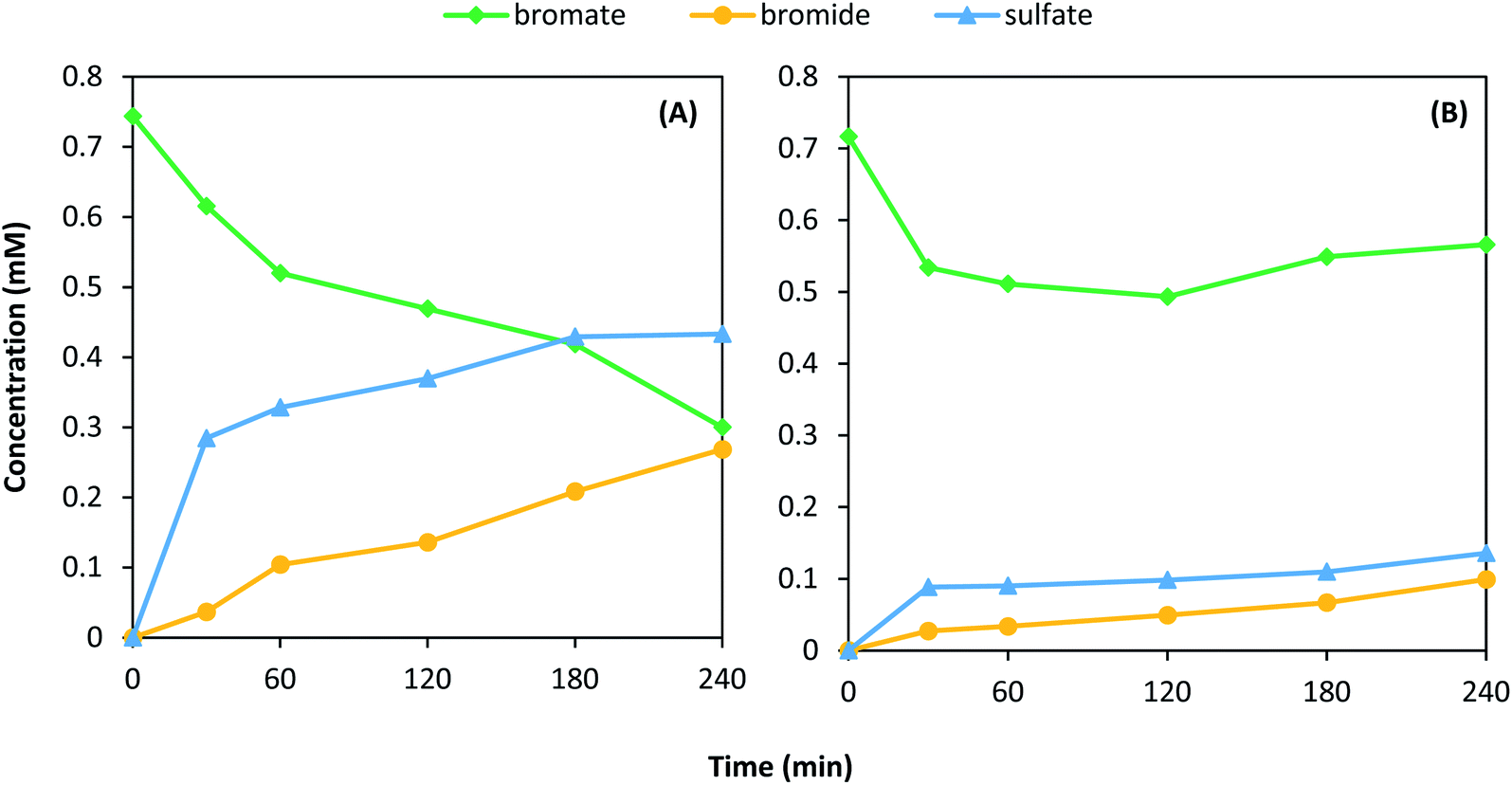 | ||
| Fig. 5 Removal of BrO3− and formation of Br− and SO42− with initial BrO3− concentration of 0.75 mM NaBrO3 and 1T-MoS2 under (A) atmospheric conditions and (B) H2 bubbling. | ||
Clearly, though proposed as an advanced material for energy and environmental applications,66 2D MoS2 will not be stable in water containing DO and other oxidants unless its surface is modified.
3.4 Stability of carbon-coated MoS2
Recently, atomically thin layers of carbon were shown to protect FeP nanoparticles from oxidation under aqueous conditions while maintaining their electrocatalytic activity.59 Using a similar method, we investigated the use of a carbon-shell coating for protecting MoS2 exposed to a solution containing a low initial concentration of NO2− (∼4 mM). Because 1T-MoS2 undergoes phase transition to 2H at approximately 95 °C,67 1T-MoS2 was not appropriate for this coating technique that requires a carbonization step at 700 °C. 2H–MoS2 was coated with carbon coatings of theoretical thicknesses of approximately 3 nm and 70 nm, and then tested for aqueous stability using similar techniques as previously described. The samples were named according to the dopamine concentration used during the synthesis (0.1 or 3.0 g L−1), and the results of 2H–MoS2/C0.1 and 2H–MoS2/C3 are shown in Fig. 6. For both thicknesses tested, results were markedly different than uncoated 2H–MoS2 under similar conditions (Fig. 3F). NO2− initially decreased but then steadied after the first hour reaching only 3.1% and 9.8% for 2H–MoS2/C0.1 and 2H–MoS2/C3, respectively. Thus, the carbon shell effectively protected MoS2 from oxidation by NO2− under the tested conditions. Because the NO2− did not continue to decrease throughout the reaction period, the observed losses are attributed to adsorption of NO2− to the carbon surface. | ||
| Fig. 6 Removal of NO2− and formation of NO3− and SO42− in the presence of (A) 2H–MoS2/C0.1 and (B) 2H–MoS2/C3. The initial target NO2− concentration was approximately 3.75 mM and the MoS2 concentration was 1 g L−1. DO was not removed. C0.1 and C3 indicates the g L−1 concentration of dopamine used in the synthesis, respectively. | ||
3.5 Electrochemical characterization of 2H–MoS2 and 2H–MoS2/C
The carbon coating of MoS2 used herein deters physical contact between the MoS2 and aqueous species, limiting its use in treatment applications such as adsorption, membrane separation, and heterogeneous catalysis. One of the main proposed applications of nanostructured MoS2 is as an electrocatalyst. In electrochemical systems, electron transfer reactions can still occur through the carbon shell, and in some cases this reaction can still be catalytic (or active).59 For example, MoS2 may be a suitable electrocatalyst for the HER, requiring a low overpotential to drive the formation of H2 as part of the overall water splitting reaction.68 In addition, the graphitic nature of the carbon coating may also provide both a conductive pathway for electron transfer and a high surface area for target species adsorption, both of which may enhance the performance of the MoS2 electrode.To examine the effects of the carbon-shell coating on the electroactivity of MoS2 as an electrocatalyst for the HER, the 2H–MoS2 was coated with three carbon thicknesses corresponding to 0.1, 2, and 3 g L−1 additions of dopamine, and then analyzed using LSV. The LSV results (Fig. 7A) were used to obtain the onset potential and the Tafel curve (Fig. 7B). The onset potential is defined herein as the potential required to reach −0.5 mA cm−2. The Tafel curve was used to obtain the Tafel slope, which indicates the potential required to increase the current ten-fold and is an indicator of the catalytic efficiency. A lower onset potential and Tafel slope implies greater efficiency.
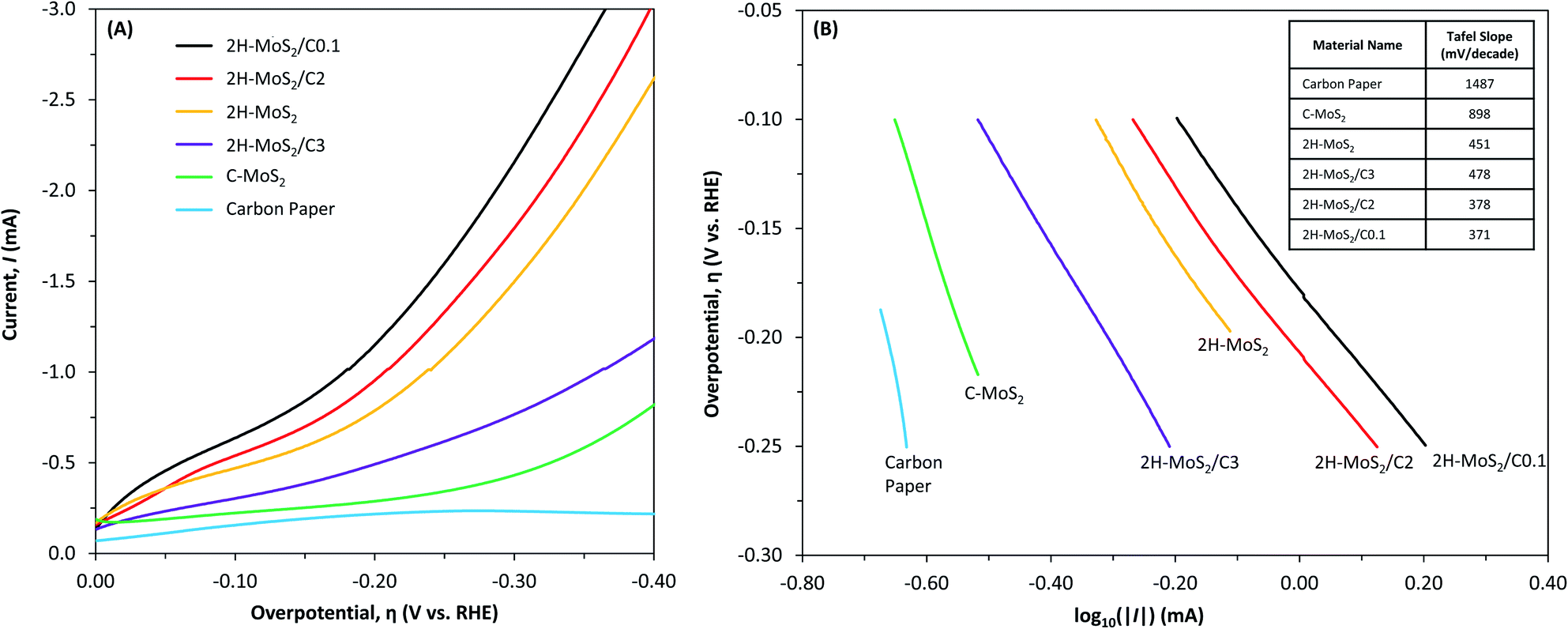 | ||
| Fig. 7 (A) Linear sweep voltammograms and (B) Tafel plots for carbon paper and MoS2 electrodes in water (no DO). The supporting electrolyte was 1 N H2SO4. The table in (B) identifies the Tafel slopes (mV per decade). | ||
The carbon paper substrate showed little activity at the potential range tested, achieving a maximum current density less than −0.3 mA cm−2 and a large Tafel slope of 1487 mV per decade. The C–MoS2 electrode had an onset potential and Tafel slope of −0.325 V and 898 mV per decade, respectively. It was less active than all 2H–MoS2 electrodes. The onset potential and Tafel slope of the 2H–MoS2 electrode was −0.115 V and 451 mV per decade, respectively. Coating the 2H–MoS2 with a carbon shell increased the activity up to a certain thickness. An improvement was observed for the 2H–MoS2/C0.1 and 2H–MoS2/C2 electrodes with an onset potential and Tafel slope of −0.060 V and −0.085 V and 371 mV per decade and 378 mV per decade, respectively. A decrease in activity was observed for the thickest coated sample, 2H–MoS2/C3, with an onset potential and Tafel slope of −0.205 V and 478 mV per decade, respectively.
One of the major issues with MoS2 is its stability when in contact with oxidants, yet the carbon shell may provide some protection while enhancing its activity. The effect of NO2− on the stability of the 2H–MoS2 and 2H–MoS2/C0.1 electrodes was evaluated by characterizing changes in the current density over time at a constant potential (Fig. 8). After 5 h of operation, the current density of the 2H–MoS2 and 2H–MoS2/C0.1 samples was −695 and −820 μA cm−1,2 respectively. In the presence of NO2−, the current densities changed to −500 and −890 μA cm−1,2 respectively. This change corresponds to a major decrease in the absolute current density for the unprotected 2H–MoS2, and its current density steadily degraded over time with no apparent steady-state condition reached over the time period tested. Thus, the 2H–MoS2 electrode was not stable in the presence of NO2−, even under cathodic, reducing conditions. For the protected 2H–MoS2/C0.1, relatively no change in the current density was observed in the presence of NO2−, and the increased current density over the unprotected 2H–MoS2 is attributed to the carbon shell.
 | ||
| Fig. 8 Chronoamperometry of 2H–MoS2 and 2H–MoS2/C0.1 electrodes in the absence and presence of NO2− (7.14 mM). The applied potential was −0.5 V vs. RHE. Samples were degassed with N2 prior to measurement. The observed noise in current density is due to effects from stirring. | ||
4. Conclusions
2D MoS2 has been proposed as a potential sustainable replacement for platinum in energy and environmental applications ranging from electrocatalytic hydrogen production to photocatalytic treatment of contaminants. Due to oxidation of the S2− and S22− edge sites, the 2H and 1T structures of 2D MoS2 are not suitable catalysts for most applications involving water without altering the water matrix or the MoS2. In the presence of DO, NO2− and BrO3− had an obvious negative impact on the stability of 2D MoS2, yet the exact reaction mechanism and pathway describing the synergistic effect needs to be elucidated. The observed dissolution of MoS2 will also presumably cause structural changes to MoS2, as shown previously for water and air matrices.54,55,65,69 To protect 2D MoS2 from oxidation, we propose two potential strategies with respect to the electrocatalytic HER that evolved from this research: (1) use pretreated water (e.g., tap water) containing relatively low concentrations of oxidants that is saturated with N2 to remove DO, or (2) add a thin shell of carbon to protect the active edge sites of MoS2, but this may also change reaction mechanisms and reduce catalytic activity. For treatment applications, where MoS2 would be used to reduce or oxidize various contaminants, removing DO may be enough to protect MoS2, even in the presence of naturally occurring oxidants.Conflicts of interest
The authors declare no conflict of interest.Acknowledgements
This work was made possible through financial support provided by the University of Notre Dame, scholarship funding for Randal Marks through the CEST/Bayer Predoctoral Research Fellowship [Center for Environmental Science and Technology at Notre Dame (CEST)] and the Patrick and Jana Eilers Graduate Student Fellowship for Energy Related Research [Center for Sustainable Energy at Notre Dame (ND Energy)]. The authors thank CEST for providing instrumentation for IC analysis and the Materials Characterization Facility for access to XRD and Raman.References
- X. Li and H. W. Zhu, Journal of Materiomics, 2015, 1, 33–44 CrossRef.
- S. Z. Butler, S. M. Hollen, L. Y. Cao, Y. Cui, J. A. Gupta, H. R. Gutierrez, T. F. Heinz, S. S. Hong, J. X. Huang, A. F. Ismach, E. Johnston-Halperin, M. Kuno, V. V. Plashnitsa, R. D. Robinson, R. S. Ruoff, S. Salahuddin, J. Shan, L. Shi, M. G. Spencer, M. Terrones, W. Windl and J. E. Goldberger, ACS Nano, 2013, 7, 2898–2926 CrossRef CAS PubMed.
- X. Huang, Z. Y. Zeng and H. Zhang, Chem. Soc. Rev., 2013, 42, 1934–1946 RSC.
- R. Ganatra and Q. Zhang, ACS Nano, 2014, 8, 4074–4099 CrossRef CAS PubMed.
- H. M. Wang, C. H. Li, P. F. Fang, Z. L. Zhang and J. Z. Zhang, Chem. Soc. Rev., 2018, 47, 6101–6127 RSC.
- Y. Yan, B. Y. Xia, Z. C. Xu and X. Wang, ACS Catal., 2014, 4, 1693–1705 CrossRef CAS.
- K. K. Kam and B. A. Parkinson, J. Phys. Chem., 1982, 86, 463–467 CrossRef CAS.
- Z. Z. Li, X. C. Meng and Z. S. Zhang, J. Photochem. Photobiol., C, 2018, 35, 39–55 CrossRef CAS.
- Y. Ding, Y. F. Zhou, W. Y. Nie and P. P. Chen, Appl. Surf. Sci., 2015, 357, 1606–1612 CrossRef CAS.
- N. N. Meng, J. Cheng, Y. F. Zhou, W. Y. Nie and P. P. Chen, Appl. Surf. Sci., 2017, 396, 310–318 CrossRef CAS.
- J. V. Lauritsen, M. Nyberg, J. K. Norskov, B. S. Clausen, H. Topsoe, E. Laegsgaard and F. Besenbacher, J. Catal., 2004, 224, 94–106 CrossRef CAS.
- L. van Haandel, J. W. Geus and T. Weber, Chemcatchem, 2016, 8, 1367–1372 CrossRef CAS.
- M. Signorile, A. Damin, A. Budnyk, C. Lamberti, A. Puig-Molina, P. Beato and S. Bordiga, J. Catal., 2015, 328, 225–235 CrossRef CAS.
- F. Cesano, S. Bertarione, A. Piovano, G. Agostini, M. M. Rahman, E. Groppo, F. Bonino, D. Scarano, C. Lamberti, S. Bordiga, L. Montanari, L. Bonoldi, R. Millini and A. Zecchina, Catal. Sci. Technol., 2011, 1, 123–136 RSC.
- J. C. Tokash and B. E. Logan, Int. J. Hydrogen Energy, 2011, 36, 9439–9445 CrossRef CAS.
- E. Ribot-Llobet, J. Y. Nam, J. C. Tokash, A. Guisasola and B. E. Logan, Int. J. Hydrogen Energy, 2013, 38, 2951–2956 CrossRef CAS.
- T. Corrales-Sanchez, J. Ampurdanes and A. Urakawa, Int. J. Hydrogen Energy, 2014, 39, 20837–20843 CrossRef CAS.
- B. Han and Y. H. Hu, Energy Sci. Eng., 2016, 4, 285–304 CrossRef CAS.
- S. Rozenfeld, H. Teller, M. Schechter, R. Farber, O. Krichevski, A. Schechter and R. Cahan, Bioelectrochemistry, 2018, 123, 201–210 CrossRef CAS PubMed.
- H. Tributsch and J. C. Bennett, J. Electroanal. Chem., 1977, 81, 97–111 CrossRef CAS.
- B. Hinnemann, P. G. Moses, J. Bonde, K. P. Jorgensen, J. H. Nielsen, S. Horch, I. Chorkendorff and J. K. Norskov, J. Am. Chem. Soc., 2005, 127, 5308–5309 CrossRef CAS PubMed.
- T. F. Jaramillo, K. P. Jorgensen, J. Bonde, J. H. Nielsen, S. Horch and I. Chorkendorff, Science, 2007, 317, 100–102 CrossRef CAS PubMed.
- A. B. Laursen, S. Kegnaes, S. Dahl and I. Chorkendorff, Energy Environ. Sci., 2012, 5, 5577–5591 RSC.
- J. D. Benck, T. R. Hellstern, J. Kibsgaard, P. Chakthranont and T. F. Jaramillo, ACS Catal., 2014, 4, 3957–3971 CrossRef CAS.
- C. G. Morales-Guio, L. A. Stern and X. L. Hu, Chem. Soc. Rev., 2014, 43, 6555–6569 RSC.
- M. S. Faber and S. Jin, Energy Environ. Sci., 2014, 7, 3519–3542 RSC.
- J. Kibsgaard, Z. B. Chen, B. N. Reinecke and T. F. Jaramillo, Nat. Mater., 2012, 11, 963–969 CrossRef CAS PubMed.
- M. A. Lukowski, A. S. Daniel, F. Meng, A. Forticaux, L. S. Li and S. Jin, J. Am. Chem. Soc., 2013, 135, 10274–10277 CrossRef CAS PubMed.
- Y. Yan, B. Y. Xia, X. M. Ge, Z. L. Liu, J. Y. Wang and X. Wang, ACS Appl. Mater. Interfaces, 2013, 5, 12794–12798 CrossRef CAS PubMed.
- J. F. Xie, J. J. Zhang, S. Li, F. Grote, X. D. Zhang, H. Zhang, R. X. Wang, Y. Lei, B. C. Pan and Y. Xie, J. Am. Chem. Soc., 2013, 135, 17881–17888 CrossRef CAS PubMed.
- J. Bonde, P. G. Moses, T. F. Jaramillo, J. K. Norskov and I. Chorkendorff, Faraday Discuss., 2008, 140, 219–231 RSC.
- D. Merki, H. Vrubel, L. Rovelli, S. Fierro and X. L. Hu, Chem. Sci., 2012, 3, 2515–2525 RSC.
- D. Z. Wang, X. Y. Zhang, Y. L. Shen and Z. Z. Wu, RSC Adv., 2016, 6, 16656–16661 RSC.
- J. Deng, H. B. Li, J. P. Xiao, Y. C. Tu, D. H. Deng, H. X. Yang, H. F. Tian, J. Q. Li, P. J. Ren and X. H. Bao, Energy Environ. Sci., 2015, 8, 1594–1601 RSC.
- D. S. Kong, H. T. Wang, J. J. Cha, M. Pasta, K. J. Koski, J. Yao and Y. Cui, Nano Lett., 2013, 13, 1341–1347 CrossRef CAS PubMed.
- X. L. Song, G. F. Chen, L. X. Guan, H. Zhang and J. G. Tao, Appl. Phys. Express, 2016, 9, 95801 CrossRef.
- F. Wypych and R. Schollhorn, J. Chem. Soc., Chem. Commun., 1992, 1386–1388 RSC.
- D. W. Murphy, F. J. Disalvo, G. W. Hull and J. V. Waszczak, Inorg. Chem., 1976, 15, 17–21 CrossRef CAS.
- G. Eda, H. Yamaguchi, D. Voiry, T. Fujita, M. W. Chen and M. Chhowalla, Nano Lett., 2011, 11, 5111–5116 CrossRef CAS PubMed.
- Q. Liu, X. L. Li, Q. He, A. Khalil, D. B. Liu, T. Xiang, X. J. Wu and L. Song, Small, 2015, 11, 5556–5564 CrossRef CAS PubMed.
- R. Lv, J. A. Robinson, R. E. Schaak, D. Sun, Y. F. Sun, T. E. Mallouk and M. Terrones, Acc. Chem. Res., 2015, 48, 56–64 CrossRef CAS PubMed.
- Q. Tang and D. E. Jiang, ACS Catal., 2016, 6, 4953–4961 CrossRef CAS.
- L. H. Zhi, W. Zuo, F. J. Chen and B. D. Wang, ACS Sustainable Chem. Eng., 2016, 4, 3398–3408 CrossRef CAS.
- J. Wang, W. T. Zhang, X. Y. Yue, Q. F. Yang, F. B. Liu, Y. R. Wang, D. H. Zhang, Z. H. Li and J. L. Wang, J. Mater. Chem. A, 2016, 4, 3893–3900 RSC.
- A. Midya, A. Ghorai, S. Mukherjee, R. Maiti and S. K. Ray, J. Mater. Chem. A, 2016, 4, 4534–4543 RSC.
- T. R. Thurston and J. P. Wilcoxon, J. Phys. Chem. B, 1999, 103, 11–17 CrossRef CAS.
- L. W. Sun, H. B. Huang and X. S. Peng, Chem. Commun., 2013, 49, 10718–10720 RSC.
- J. L. Kou, J. Yao, L. L. Wu, X. Y. Zhou, H. J. Lu, F. M. Wu and J. T. Fan, Phys. Chem. Chem. Phys., 2016, 18, 22210–22216 RSC.
- X. Yang, J. Li, T. Liang, C. Y. Ma, Y. Y. Zhang, H. Z. Chen, N. Hanagata, H. X. Su and M. S. Xu, Nanoscale, 2014, 6, 10126–10133 RSC.
- S. Pandit, S. Karunakaran, S. K. Boda, B. Basu and M. De, ACS Appl. Mater. Interfaces, 2016, 8, 31567–31573 CrossRef CAS PubMed.
- B. L. Liu, L. Chen, G. Liu, A. N. Abbas, M. Fathi and C. W. Zhou, ACS Nano, 2014, 8, 5304–5314 CrossRef CAS PubMed.
- J. R. Eskelsen, J. Xu, M. Chiu, J. W. Moon, B. Wilkins, D. E. Graham, B. H. Gu and E. M. Pierce, Environ. Sci. Technol., 2018, 52, 1139–1149 CrossRef CAS PubMed.
- P. Zhang and S. H. Yuan, Geochim. Cosmochim. Acta, 2017, 218, 153–166 CrossRef CAS.
- T. W. Lee, C. C. Chen and C. Y. Chen, Environ. Sci. Technol., 2019, 53, 6282–6291 CrossRef CAS PubMed.
- Z. Y. Wang, A. von dem Bussche, Y. Qiu, T. M. Valentin, K. Gion, A. B. Kane and R. H. Hurt, Environ. Sci. Technol., 2016, 50, 7208–7217 CrossRef CAS PubMed.
- C. Yang, Z. X. Chen, I. Shakir, Y. X. Xu and H. B. Lu, Nano Res., 2016, 9, 951–962 CrossRef CAS.
- B. J. Guo, Y. Feng, X. F. Chen, B. Li and K. Yu, Appl. Surf. Sci., 2018, 434, 1021–1029 CrossRef CAS.
- Y. M. Li, A. Yamaguchi, M. Yamamoto, K. Taka and R. Nakamura, J. Phys. Chem. C, 2017, 121, 2154–2164 CrossRef CAS.
- D. Y. Chung, S. W. Jun, G. Yoon, H. Kim, J. M. Yoo, K. S. Lee, T. Kim, H. Shin, A. K. Sinha, S. G. Kwon, K. Kang, T. Hyeon and Y. E. Sung, J. Am. Chem. Soc., 2017, 139, 6669–6674 CrossRef CAS PubMed.
- Z. P. Liu, Z. C. Gao, Y. H. Liu, M. S. Xia, R. W. Wang and N. Li, ACS Appl. Mater. Interfaces, 2017, 9, 25291–25297 CrossRef CAS PubMed.
- B. P. Chaplin, M. Reinhard, W. F. Schneider, C. Schuth, J. R. Shapley, T. J. Strathmann and C. J. Werth, Environ. Sci. Technol., 2012, 46, 3655–3670 CrossRef CAS PubMed.
- X. Chen, X. C. Huo, J. Y. Liu, Y. Wang, C. J. Werth and T. J. Strathmann, Chem. Eng. J., 2017, 313, 745–752 CrossRef CAS.
- R. Marks, T. Yang, P. Westerhoff and K. Doudrick, Water Res., 2016, 104, 11–19 CrossRef CAS PubMed.
- P. Westerhoff, J. Environ. Eng., 2003, 129, 10–16 CrossRef CAS.
- P. Afanasiev and C. Lorentz, J. Phys. Chem. C, 2019, 123, 7486–7494 CrossRef CAS.
- Z. Y. Wang and B. X. Mi, Environ. Sci. Technol., 2017, 51, 8229–8244 CrossRef CAS.
- A. N. Enyashin, L. Yadgarov, L. Houben, I. Popov, M. Weidenbach, R. Tenne, M. Bar-Sadan and G. Seifert, J. Phys. Chem. C, 2011, 115, 24586–24591 CrossRef CAS.
- D. Voiry, M. Salehi, R. Silva, T. Fujita, M. W. Chen, T. Asefa, V. B. Shenoy, G. Eda and M. Chhowalla, Nano Lett., 2013, 13, 6222–6227 CrossRef CAS PubMed.
- W. L. Spychalsid, M. Pisarek and R. Szoszkiewicz, J. Phys. Chem. C, 2017, 121, 26027–26033 CrossRef.
| This journal is © The Royal Society of Chemistry 2020 |