 Open Access Article
Carbon electrode engineering for high efficiency all-inorganic perovskite solar cells†
Longfei Mi *ab,
Yan Zhangb,
Taotao Chenb,
Enze Xub and
Yang Jiang
 *b
*b
aDepartment of Materials Science and Engineering, School of Civil Engineering, Qingdao University of Technology, Qingdao, Shandong 266000, P. R. China. E-mail: mlf19881231@163.com
bSchool of Materials Science and Engineering, Hefei University of Technology, Hefei, Anhui 230009, P. R. China
First published on 26th March 2020
Abstract
Carbon-based inorganic perovskite solar cells (PSCs) have demonstrated an excellent performance in the field of photovoltaics owing to their simple fabrication techniques, low-cost and superior stability. Despite the lower efficiency of devices with a carbon electrode compared with the conventional structure, the potential applications in large scale have attracted increasing attention. Herein, we employ a mixed carbon electrode inorganic PSC by incorporating one-dimensional structure carbon nanotubes (CNTs) and two-dimensional Ti3C2-MXene nanosheets into a commercial carbon paste. This mixed carbon electrode, which is different from the pure carbon electrode in showing a point-to-point contact, provides a network structure and multi-dimensional charge transfer path, which effectively increases the conductivity of the carbon electrode and carriers transport. A respectable power conversion efficiency of 7.09% is obtained through carbon/CNT/MXene mixed electrode in CsPbBr3-based solar cells.
1 Introduction
Hybrid organic–inorganic perovskite materials, as potential candidates in the solar energy conversion, have drawn considerable attention owing to their broad absorption wavelength (up to ∼800 nm), strong absorption coefficient, high carrier mobility and facile processing techniques.1–6 Since the first report in 2009 with an initial power conversion efficiency (PCE) of 3.8%,7 a rapid development of hybrid organic–inorganic perovskite solar cells (PSCs) and various robust deposition techniques, i.e., one-step/two-step solution strategy,6,8–10 vapor deposition11–15 and vapor-assisted solution method,16–18 have ensured a champion PCE of above 25.2% in the past decade.19 However, the perovskite solar cells (PSCs) based on the hybrid counterparts such as methylammonium lead halide (MAPbX3) and formamidinium lead halide (FAPbX3) suffers from the inferior stability because of the decomposition of fragile cation materials under moisture and thermal attacks, which impede their commercial applications in the future.20,21The inorganic materials (CsPbX3, X = I, Br and Cl) inherit the superior properties of hybrid counterparts and alleviate the instability issues of devices by substituting MA+/FA+ with inorganic cations such as cesium (Cs+) and rubidium (Rb+).22–24 A record PCE of 18.3% and 10.9% for pure CsPbI3 PSCs and CsPbBr3 PSCs, respectively, have been achieved in recent studies, which makes the inorganic PSCs promising candidates in photovoltaics.25–28 To date, the general configuration of PSCs employ the hole transfer layer (HTL), i.e., spiro-OMeTAD, PTAA and NiOx, which impedes them in the large scale in the realized application because of the high-cost of the organic transfer materials and extremely sensitive to humidity and thermal environment.29–31 Very recently, a HTL-free structure is proposed by using a carbon paste as the counter electrode to replace the silver/gold electrode as well as HTL. For example, an all-inorganic CsPbBr3-PSC with a carbon electrode was demonstrated, which showed an outstanding PCE of 9.7% accompanying with no performance degradation in moisture and heating conditions.32 Similar to bromide-based PSCs, an α-CsPbI3 HTL-free solar cell was constructed by employing a carbon electrode, and it presented a high efficiency of 9.5%.33 Notably, this device showed a high stable performance and retained 90% of the initial efficiency. In addition, a mixed halide PSC, such as CsPbI2Br and CsPbIBr2 inorganic PSCs, also exhibited high efficiency and high stability on combining with a carbon electrode,34,35 which indicated that combining a carbon counter electrode to PSCs is a universal technique to improve the stability of all inorganic PSCs. The performances of the CsPbBr3 PSCs with a carbon electrode are summarized in Table S1.† Although the initial PCE of the device without HTL is weaker than that containing HTL, it shows lower cost and better stability in air. Furthermore, the blade coating for depositing the carbon electrode, compared with the spin-coating, has been proposed as an innovative strategy in the commercial and academic fields because of the better continuous work and lower waste during the coating procedure.36,37
It is worth noticing that the commercial carbon paste displays a point contact with the perovskite layer because of the particle-to-particle contact in the carbon electrode. Nevertheless, a large amount of pinholes exists at the interface of the carbon electrode/perovskite film, which is a serious concern for the carrier transport and shows a lower conductivity.38 On the contrary, carbon nanotubes (CNTs) with a one-dimensional (1D) structure can provide high conductivity and direct transport path for carriers.39 Simultaneously, Ti3C2-MXene displaying a two-dimensional (2D) layer structure gives an outstanding electrical conductivity and large surface area, which accelerate the carrier transport in the layer.40–42
In this study, we propose a novel mixed-carbon electrode by the incorporation of commercial carbon nanotubes and Ti3C2-MXene nanosheets into carbon paste, wherein the CNTs and MXene effectively increase the conductivity of the carbon electrode and carrier transport by constructing a three-dimensional (3D) carrier transfer path. A superior efficiency of 7.09% is achieved with a configuration of FTO/c-TiO2/CsPbBr3/mixed carbon. Furthermore, we anticipated that this mixed carbon electrode will pave a novel route for photovoltaics to enhance the efficiency and stability in the large-scale application in the future.
2 Materials and methods
2.1 CsPbBr3 film
First, CsBr, PbBr2 powder and clean substrates were placed into a vacuum chamber. Then, the chamber was pumped to a high vacuum degree of ∼10−3 Pa, and a heating source A was turned on to evaporate the CsBr with a speed of 0.5 Å s−1. Further, the PbBr2 powder was deposited at a rate of 0.8 Å s−1 in source B. Finally, the samples were annealed at a high temperature (300 °C) for 20 min in air to form an inorganic CsPbBr3 thin film. The thickness of CsBr and PbBr2 films in this experiment are 125 nm and 175 nm, respectively.2.2 Mixed carbon paste
The commercial carbon paste and commercial carbon nanotubes were purchased from Shanghai MaterWin New Material. Co., Ltd and Shenzhen Sanshun Corporation, respectively. Ti3AlC2 powder was purchased from Jilin 11 Technology Co., Ltd. Following this the first step was to get Ti3C2-MXene. To etch the Ti3AlC2 powder, 20 ml of HF (40%) solution was used to dissolve 1 g of the raw powder and kept stirring for a whole day. After etching, deionized water was added for several times until the pH of the solution was above 5. Then, the as-prepared powders were moved to a vacuum drying oven to heat it for overnight (60 °C, 12 h). 0.5 g of Ti3C2Tx powder was dissolved in 10 ml of a 25% tetramethylammonium hydroxide aqueous solution (TMAOH) to delaminate the Ti3C2Tx. After washing, centrifugation and sonication for several times, the Ti3C2-MXene nanosheets were obtained.40 The mixed carbon paste was fabricated by mixing with the carbon paste for overnight. The weight ratio of carbon nanotubes and MXene are 1![[thin space (1/6-em)]](https://www.rsc.org/images/entities/char_2009.gif) :
:![[thin space (1/6-em)]](https://www.rsc.org/images/entities/char_2009.gif) 0.5
0.5![[thin space (1/6-em)]](https://www.rsc.org/images/entities/char_2009.gif) :
:![[thin space (1/6-em)]](https://www.rsc.org/images/entities/char_2009.gif) 0.1.
0.1.
2.3 Device fabrication
Commercial FTO (7–8 Ω sq−1) substrates were washed with acetone, ethyl alcohol and deionized water, respectively. Each step was done for 30 min. Then, the titanium isopropoxide precursor solution was spin-coated on FTO substrates at a speed of 2000 rpm for 40 s to form a compact TiO2 layer. After sintering at 450 °C in air for 30 min, the substrates were treated with a TiCl4 aqueous solution (40 mM) at 70 °C for 30 min and then annealed at 450 °C for another 30 min to get a high-quality c-TiO2 thin film. The CsPbBr3 inorganic perovskite absorption layer was deposited via a thermal evaporation method. A different kind of carbon ink was coated on the top layer of the perovskite film via doctor-blade coating as the counter electrode and was treated at 80 °C for several minutes in air.2.4 Characterization
XRD measurements were conducted via XRD using Cu Kα X-ray radiation. Data were collected from 10° to 60° two theta degrees. The absorption and PL spectra were recorded using a UV-visible spectrophotometer (UV-2550) and a Hitachi F-4600 fluorescence spectrophotometer. SEM characterizations of the samples were performed using a scanning electron microscope (Sigma Zeiss and Hitachi SU8020). Current–voltage (J–V) plots of inorganic perovskite devices were measured using a Keithley 2636 system sourcemeter under an AM 1.5 G simulated solar illumination with a light intensity of ∼100 mW cm−2. The active area of each sample is 0.09 cm2. All the tests were conducted in open air.3 Result and discussion
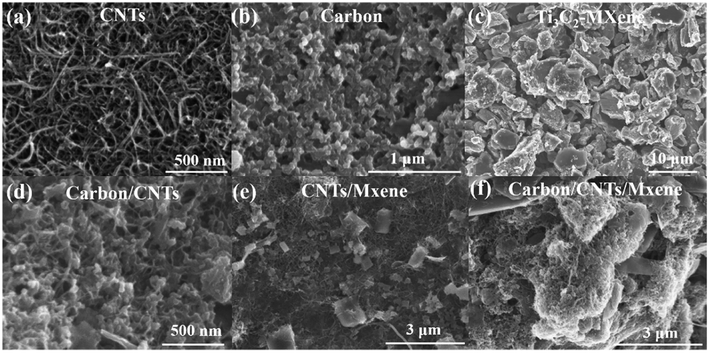
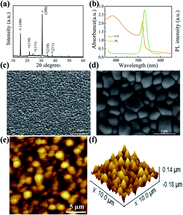
The CsPbBr3 perovskite film was fabricated via a two-step vapor deposition. As can be seen in Fig. 1a, the typical characteristic peaks of the as-prepared CsPbBr3 film after annealing found at 15.18°, 21.55°, 26.48°, 30.64°, 34.37°, and 37.76° can be assigned to the (100), (110), (111), (200), (210) and (211) lattice planes. To analyze the optical properties of the sample, UV-vis absorption and photoluminescence (PL) were conducted, and the corresponding curves are displayed in Fig. 1b. A high PL peak at 528 nm and cut-off edge of light absorption spectrum at 550 nm can be seen clearly, which are consistent with those obtained in previous studies.22,29 The top-view scanning electron microscope (SEM) images in Fig. 1c and d show a compact layer with a large grain size. The largest grain size of perovskite crystals is over 1 μm. This high crystallinity of perovskite grains can effectively reduce the defect density and is beneficial for the electron and hole separation and transport. Furthermore, the as-prepared film produced by the vapor deposition shows a smooth surface with a root-mean-square roughness (RMS) of 30.5 nm (Fig. 1e and f), which is beneficial for a better contact between the carbon electrode and perovskite layer.The surface morphologies of pure carbon nanotubes, carbon paste and Ti3C2-MXene are shown in Fig. 2a–c, respectively. The long chain-like structure of CNTs accelerates them cross together to construct a continuous and crack-free thin film. Different from the one-dimensional structure, carbon powders show a spherical structure with a three-dimensional architecture. Surprisingly, Ti3C2-MXene nanosheets present an accordion-like two-dimensional layer structure with a thickness of ∼2 μm. After mixing and stirring, CNTs and Ti3C2-MXene can be well-distributed in the carbon paste (Fig. 2d and e). It is worth noticing that the particles closely pack because of the existence of a binder in the commercial carbon paste. The carbon powders are well coated with CNTs. Moreover, the voids of carbon powders are filled with MXene nanosheets (Fig. 2f). In this case, the carrier can be effectively collected and transported.
 | ||
| Fig. 2 Top-view SEM images of (a) CNTs, (b) carbon paste, (c) Ti3C2-MXene, (d) carbon/CNTs, (e) CNT/MXene and (f) carbon/CNT/MXene. | ||
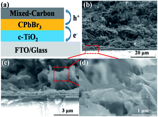
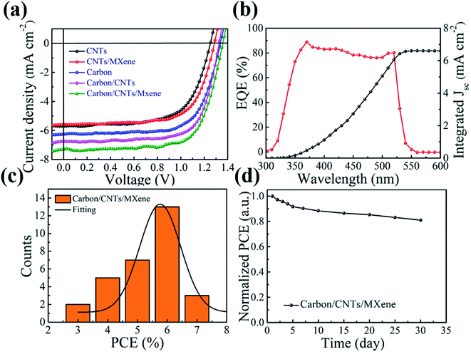
To further evaluate the performance of the mixed carbon electrode, a series of devices were assembled with a configuration of FTO/c-TiO2/CsPbBr3/mixed carbon (as shown in Fig. 3a), where TiO2 and carbon serve as an electron transfer layer and counter electrode, respectively. The CsPbBr3 thin film is an active layer, which can generate the electron and hole pairs under light illumination. The electron and hole will be separated and transported quickly to the FTO and counter electrode under built-in electric field.43,44 Fig. 3b and c are the typical cross-section of devices with the mixed carbon electrode. The full coverage and continuous perovskite layer can be found in the SEM image. Good interface contact between the perovskite and carbon electrode ensures the hole transport to the counter electrode. Fig. 4a presents the current density–voltage (J–V) curves of the CsPbBr3 solar cells with the mixed carbon electrode. The parameters voltage (Voc), photocurrent density (Jsc) and fill factor (FF) are summarized in Table 1. The lower PCE of 4.77% for the devices with pure CNTs comes from the poor surface contact between the perovskite and counter electrode. Similarly, the device with pure carbon paste shows a higher PCE of 5.87% because of the better interface contact. However, the appearance of CNTs in the carbon electrode can significantly increase the photocurrent density due to the high mobility of CNTs. A respectable PCE of 7.09% with a Voc of 1.357 V, a Jsc of 7.16 mA cm−2 and an FF of 72.97% is obtained after the incorporation of CNTs and MXene into the carbon paste. As shown in Fig. S1 and Table S2,† the hysteresis of devices with mixed carbon electrodes was reduced in comparison with the pure carbon electrode CsPbBr3 PSCs. The EQE spectrum in Fig. 4b displays a broad plateau of over 80% ranging from 350 to 500 nm. The corresponding photocurrent density extracted from the integration of EQE is closer to the value obtained from J–V curves. This excellent performance can be well explained by the carrier transport by mixed carbon. The pure carbon electrode shows a point-to-point contact, which means that the carrier transfer in the carbon electrode by particle-to-particle is expected to be much slow. With the appearance of CNTs, the one-dimensional structure provides a high-speed transport route for the carriers, which can accelerate the carrier transport. Moreover, MXene nanosheets are expected to improve the conductivity of the carbon electrode because of the higher conductivity and carrier mobility than graphene.45 Most importantly, the small sizes of MXene can effectively fill in the voids in the carbon electrode and improve the contact of carbon particles. This point-line-layer contact structure is encouraged to improve the carbon electrode conductivity and accelerates carrier transport. Furthermore, this mixed carbon electrode strategy displays a good repeatability. As seen in Fig. 4c, the PCEs of 30 devices are well distributed in a narrow range from 3% to 7%. The CsPbBr3 solar cell using the mixed carbon electrode shows excellent stability in moisture. After storing in air for one month, the device kept 80% of the initial performance (Fig. 4d). The performance decrease is probably due to (1) the inevitable decomposition of CsPbBr3 in moisture; (2) the oxidation of Ti3C2 to TiOx caused by high humidity and oxygen in the air, which decrease the mobility of MXene and impede the carrier fast transport.46
| Device | Voc (V) | Jsc (mA cm−2) | FF (%) | PCE (%) |
|---|---|---|---|---|
| CNTs | 1.250 | 5.81 | 65.68 | 4.77 |
| CNT/MXene | 1.286 | 5.52 | 69.73 | 4.95 |
| Carbon | 1.336 | 6.15 | 71.44 | 5.87 |
| Carbon/CNTs | 1.328 | 6.85 | 71.96 | 6.55 |
| Carbon/CNT/MXene | 1.357 | 7.16 | 72.97 | 7.09 |
4 Conclusion
In summary, we produced a high efficiency inorganic perovskite solar cell by introducing a mixed carbon electrode. The appearance of CNTs and Ti3C2-MXene can enhance the surface contact with carbon paste and promote the electrode conductivity. Moreover, compared with the traditional point-to-point transfer, the multi-dimensional charge transfer path can effectively improve the carrier extraction and transport, which produce an impressive PCE of 7.09%. These results show that the mixed carbon electrode can provide a novel method to prepare hole transport layer free inorganic PSCs with high PCE and has a potential for large scale applications in the future.Conflicts of interest
There are no conflicts to declare.Acknowledgements
We thanked the Qingdao University of Technology Staring Foundation (grant 20301721, 20302041), and National Natural Science Foundation of China (grant U1632151).References
- M. Liu, M. B. Johnston and H. J. Snaith, Nature, 2013, 501, 395–398 CrossRef CAS PubMed
.
- Y. Zhao and K. Zhu, Chem. Soc. Rev., 2016, 45, 655–689 RSC
.
- Z. Song, G. Tong, H. Li, G. Li, S. Ma, S. Yu, Q. Liu and Y. Jiang, Nanotechnology, 2018, 29, 025401 CrossRef PubMed
.
- G. Tong, H. Li, Z. Zhu, Y. Zhang, L. Yu, J. Xu and Y. Jiang, J. Phys. Chem. Lett., 2018, 9, 1592–1599 CrossRef CAS PubMed
.
- J. Shu, X. Zhang, P. Wang, R. Chen, H. Zhang, D. Li, P. Zhang and J. Xu, Phys. B, 2018, 548, 53–57 CrossRef CAS
.
- J. Lu, X. Sheng, G. Tong, Z. Yu, X. Sun, L. Yu, X. Xu, J. Wang, J. Xu, Y. Shi and K. Chen, Adv. Mater., 2017, 29, 1700400 CrossRef PubMed
.
- A. Kojima, K. Teshima, Y. Shirai and T. Miyasaka, J. Am. Chem. Soc., 2009, 131, 6050–6051 CrossRef CAS PubMed
.
- N. J. Jeon, J. H. Noh, Y. C. Kim, W. S. Yang, S. Ryu and S. I. Seok, Nat. Mater., 2014, 13, 897–903 CrossRef CAS PubMed
.
- D. Bi, C. Yi, J. Luo, J.-D. Décoppet, F. Zhang, S. M. Zakeeruddin, X. Li, A. Hagfeldt and M. Grätzel, Nat. Energy, 2016, 1, 16142 CrossRef CAS
.
- M. Xiao, F. Huang, W. Dkhissi, Y. Zhu, J. Etheridge, A. Gray-Weale, U. Bach, Y.-B. Cheng and L. Spiccia, Angew. Chem., Int. Ed., 2014, 53, 9898–9903 CrossRef CAS PubMed
.
- G. Tong, H. Li, G. Li, T. Zhang, C. Li, L. Yu, J. Xu, Y. Jiang, Y. Shi and K. Chen, Nano Energy, 2018, 48, 536–542 CrossRef CAS
.
- L. K. Ono, M. R. Leyden, S. Wang and Y. B. Qi, J. Mater. Chem. A, 2016, 4, 6693–6713 RSC
.
- C.-Y. Chen, H.-Y. Lin, K.-M. Chiang, W.-L. Tsai, Y.-C. Huang, C.-S. Tsao and H.-W. Lin, Adv. Mater., 2017, 29, 1605290–1605296 CrossRef PubMed
.
- Q. Ma, S. Huang, X. Wen, M. A. Green and A. W. Y. Ho-Baillie, Adv. Energy Mater., 2016, 6, 1502202 CrossRef
.
- G. Tong, Z. Song, G. Li, Y. Zhao, L. Yu, J. Xu, Y. Jiang, Y. Sheng and Y. Chen, RSC Adv., 2017, 7, 19457–19463 RSC
.
- D. Shan, G. Tong, Y. Cao, M. Tang, J. Xu, L. Yu and K. Chen, Nanoscale Res. Lett., 2019, 14, 208–213 CrossRef PubMed
.
- G. Tong, X. Lan, Z. Song, G. Li, H. Li, L. Yu, J. Xu, Y. Jiang, Y. Sheng and K. Chen, Mater. Today Energy, 2017, 5, 173–180 CrossRef
.
- G. Tong, X. Geng, Y. Yu, L. Yu, J. Xu, Y. Jiang, Y. Sheng, Y. Shi and K. Chen, RSC Adv., 2017, 7, 18224–18230 RSC
.
- https://www.nrel.gov/pv/assets/pdfs/best-research-cell-efficiencies-190416.pdf, 2019.
- J. Liang, J. Liu and Z. Jin, Sol. RRL, 2017, 1, 1700086–1700109 CrossRef
.
- G. Tong, H. Li, D. Li, Z. Zhu, E. Xu, G. Li, L. Yu, J. Xu and Y. Jiang, Small, 2018, 14, 1702523–1702530 CrossRef PubMed
.
- J. Liang, C. Wang, Y. Wang, Z. Xu, Z. Lu, Y. Ma, H. Zhu, Y. Hu, C. Xiao, X. Yi, G. Zhu, H. Lv, L. Ma, T. Chen, Z. Tie, Z. Jin and J. Liu, J. Am. Chem. Soc., 2016, 138, 15829–15832 CrossRef CAS PubMed
.
- M. Saliba, T. Matsui, J.-Y. Seo, K. Domanski, J.-P. Correa-Baena, M. K. Nazeeruddin, S. M. Zakeeruddin, W. Tress, A. Abate, A. Hagfeldt and M. Grätzel, Energy Environ. Sci., 2016, 9, 1989–1997 RSC
.
- M. Saliba, T. Matsui, K. Domanski, J.-Y. Seo, A. Ummadisingu, S. M. Zakeeruddin, J.-P. Correa-Baena, W. R. Tress, A. Abate, A. Hagfeldt and M. Grätzel, Science, 2016, 354, 206–209 CrossRef CAS PubMed
.
- G. Tong and L. K. Ono, Energy Technol., 2019 DOI:10.1002/ente.201900961
.
- Y. Wang, T. Zhang, M. Kan and Y. Zhao, J. Am. Chem. Soc., 2018, 140, 12345–12348 CrossRef CAS PubMed
.
- G. Tong, T. Chen, H. Li, L. Qiu, Z. Liu, Y. Dang, W. Song, L. K. Ono, Y. Jiang and Y. B. Qi, Nano Energy, 2019, 65, 104015 CrossRef CAS
.
- Y. Wang, M. I. Dar, L. K. Ono, T. Zhang, M. Kan, Y. Li, L. Zhang, X. Wang, Y. Yang, X. Gao, Y. B. Qi, M. Grätzel and Y. Zhao, Science, 2019, 365, 591–595 CrossRef CAS PubMed
.
- H. Li, G. Tong, T. Chen, H. Zhu, G. Li, Y. Chang, L. Wang and Y. Jiang, J. Mater. Chem. A, 2018, 6, 14255–14261 RSC
.
- H. Yuan, Y. Zhao, J. Duan, Y. Wang, X. Yang and Q. Tang, J. Mater. Chem. A, 2018, 6, 24324–24329 RSC
.
- K. Wang, Z. Jin, L. Liang, H. Bian, D. Bai, H. Wang, J. Zhang, Q. Wang and S. Liu, Nat. Commun., 2018, 9, 544 CrossRef PubMed
.
- J. Duan, Y. Zhao, B. He and Q. Tang, Angew. Chem., Int. Ed., 2018, 57, 3787–3791 CrossRef CAS PubMed
.
- S. Xiang, Z. Fu, W. Li, J. Liu, H. Liu, L. Zhu, R. Zhang and H. Chen, ACS Energy Lett., 2018, 3, 1824–1831 CrossRef CAS
.
- Z. Guo, S. Zhao, A. Liu, Y. Kamata, S. Teo, S. Yang, Z. Xu, S. Hayase and T. Ma, ACS Appl. Mater. Interfaces, 2019, 11, 19994–20003 CrossRef CAS PubMed
.
- Z. Guo, S. Teo, Z. Xu, C. Zhang, Y. Kamata, S. Hayase and T. Ma, J. Mater. Chem. A, 2014, 7, 1227–1232 RSC
.
- A. Mei, X. Li, L. Liu, Z. Ku, T. Liu, Y. Rong, M. Xu, M. Hu, J. Chen, Y. Yang, M. Grätzel and H. Han, Science, 2014, 345, 295–298 CrossRef CAS PubMed
.
- G. Tong, T. Chen, H. Li, W. Song, Y. Chang, J. Liu, L. Yu, J. Xu, Y. B. Qi and Y. Jiang, Sol. RRL, 2019, 3, 1900030 CrossRef
.
- Z. Wei, H. Chen, K. Yan, X. Zheng and S. Yang, J. Mater. Chem. A, 2015, 3, 24226–24231 RSC
.
- S. N. Habisreutinger, R. J. Nicholas and H. J. Snaith, Adv. Energy Mater., 2017, 7, 1601839 CrossRef
.
- L. Yang, Y. Dall'Agnese, K. Hantanasirisakul, C. E. Shuck, K. Maleski, M. Alhabeb, G. Chen, Y. Gao, Y. Sanehira, A. K. Jena, L. Shen, C. Dall'Agnese, X.-F. Wang, Y. Gogotsi and T. Miyasaka, J. Mater. Chem. A, 2019, 7, 5635–5642 RSC
.
- Z. Guo, L. Gao, Z. Xu, S. Teo, C. Zhang, Y. Kamata, S. Hayase and T. Ma, Small, 2018, 14, 1802738 CrossRef PubMed
.
- T. Chen, G. Tong, E. Xu, H. Li, P. Li, Z. Zhu, J. Tang, Y. Qi and Y. Jiang, J. Mater. Chem. A, 2019, 7, 20597–20603 RSC
.
- Q. Wang, Y. Shao, H. Xie, L. Lyu, X. Liu, Y. Gao and J. Huang, Appl. Phys. Lett., 2014, 105, 163508 CrossRef
.
- W. A. Laban and L. Etgar, Energy Environ. Sci., 2013, 6, 3249–3253 RSC
.
- H. Wang, Y. Wu, X. Yuan, G. Zeng, J. Zhou, X. Wang and J. W. Chew, Adv. Mater., 2018, 30, 1704561 CrossRef PubMed
.
- L. Yu, A. S. R. Bati, T. S. L. Grace, M. Batmunkh and J. G. Shapter, Adv. Energy Mater., 2019, 11, 1901063 CrossRef
.
Footnote |
| † Electronic supplementary information (ESI) available. See DOI: 10.1039/d0ra00288g |
| This journal is © The Royal Society of Chemistry 2020 |


