DOI:
10.1039/D0RA00188K
(Paper)
RSC Adv., 2020,
10, 13708-13716
Large magnetodielectric effect and negative magnetoresistance in NiO nanoparticles at room temperature
Received
8th January 2020
, Accepted 3rd March 2020
First published on 3rd April 2020
Abstract
Nickel oxide nanoparticles having a mean particle size of 19.5 nm were synthesized by a simple chemical method. Those nanoparticles exhibited a spin glass like behaviour at a temperature around 9 K. The samples showed electronic conduction arising out of small polaron hopping between the Ni2+ and Ni3+ species present in the material. A large magnetodielectric parameter with a maximum value of 52.2% was observed in the sample at room temperature which resulted from the Maxwell–Wagner polarization effect. This was explained as arising due to a large negative magnetoresistance caused by spin polarized electron hopping between Ni2+ and Ni3+ sites with the consequential formation of space charge polarization at the interfaces of the NiO nanoparticles. This was substantiated by direct measurement of magnetoresistance of the samples which gave identical results. It is believed that negative magnetoresistance after direct measurement occurred due to the interaction between ferromagnetic and antiferromagnetic phases and the value was 37%, the highest reported in the literature so far. As a result of the presence of Ni3+ ions, antiferromagnetic phase and ferromagnetic like behaviour of NiO nanoparticles gave higher magnetization than other reported nanoparticles. Such large values of magnetoresistance of the samples will make the material useful as an ideal magnetic sensor.
Introduction
Nanostructured materials e.g., nanoparticles exhibit unique physical and chemical properties compared to bulk materials and have been investigated very much in the last few years.1 They have attracted significant interest as they have large surface areas.2,3 They possess novel electrical, magnetic and optical properties that are useful for different applications.4,5 Nickel oxide (NiO) nanoparticles have been studied lately because of their very useful applications viz., as catalysts, gas sensors, electrochromic films, dye-sensitized photo cathodes, electrode materials for fuel cells, batteries etc.6–13 Various synthesis techniques of NiO nanoparticles have been attempted and reported in recent years by many researchers14–17 to have variety of applications. The magnetic properties of transition metal oxides are getting attention due to their structural aspects.18,19 Several investigations were done on NiO nanoparticles to study magnetism and magnetic interaction which have received great attention due to novel magnetic properties since Néel20 and Brown21 developed a magnetization relaxation theory for non-interconnecting single domain nanoparticles.10,22–24 NiO nanoparticles generally exhibit antiferromagnetism with a Néel temperature at 523 K which is involved in various applications.20,25,26 The magnetic property is dependent on size and surface morphology of the nanoparticles. Size dependent magnetic properties of NiO was first reported by Richardson.27 According to Néel in 1961, weak ferromagnetism or superparamagnetism will be exhibited by fine NiO nanoparticles of antiferromagnetic nature and permanent magnetic moment will be assigned to uncompensated spins in the two sublattices at the surface of the particles. So, ferromagnetic-like behaviour in NiO nanoparticles was reported by various researchers.10,20,28–30 In this paper, it is shown that, NiO nanoparticles exhibit ferromagnetic like behaviour in contrast to antiferromagnetism at higher fields. This has been explained as arising due to the presence of uncompensated spins associated with Ni3+ ions in the material. Magnetodielectric effect in nanomaterials and composites have received a lot of attention in recent times because of their potential application in nanodimensional devices.31–39 This effect arises due to the formation of a space charge layer at the interface between two phases having different electrical conductivities (Maxwell–Wagner dielectric).40 This contributes to the dielectric permittivity of the specimen. Application of a magnetic field may contribute to a change of permittivity by either of two possible mechanisms viz., either by movement of electric charges in a direction perpendicular to those of the applied electric and magnetic fields respectively41 or a change of electrical conductivity of one of the phases present40 as a function of applied magnetic field. In this paper, we have explored the magnetic properties of NiO nanoparticles with small particle sizes than previously reported result10 where these particles exhibit ferromagnetic like behaviour with antiferromagnetism at higher fields. The spin glass like state was found in this material with high magnetodielectric effect in the light of our results given below on their magnetic properties. It had been reported earlier that certain nanocrystalline compounds based on La–Ca–Mn–O exhibited spin-glass behaviour possessing a large magnetoresistance characteristics.42,43 An increase in electrical conductivity of such a material by the application of a magnetic field would therefore bring about a large increase in the formation of a space charge region at their interfaces with the insulating phase surrounding itself resulting in a big change of dielectric permittivity of the system. Materials which exhibit magnetoresistance play the most important role in applications concerning magnetic recording and sensing44–46 nowadays due to their unique structural, magnetic and electronic properties. Magnetoresistance effect of NiO nanoparticles was explored in this paper and the theoretical value extracted from magnetodielectric data was found to be 52.5% at frequency 20 kHz at a magnetic field of 1.6 tesla. Also the direct measurement of magnetoresistance gave very high value [37% at room temperature] at a magnetic field of 1.6 tesla as compared to other published reports. These NiO nanoparticles were prepared by a simple chemical route which is also advantageous than other results. Large values of magnetodielectric parameters at room temperature were indeed observed in compacted NiO nanoparticles. The details are reported in this paper.
Experimental procedure
Synthesis
NiO nanoparticles were prepared by a simple method.47 All precursor materials were purchased from Sigma-Aldrich. The materials used were NiCl2 and NaHCO3. 2.3 g NiCl2 and 1.5 g NaHCO3 were dissolved in 10 ml distilled water separately and the two solutions were stirred for 15 minutes. The second solution (1.5 g NaHCO3 + 10 ml distilled water) was then added dropwise to the first solution under constant stirring for 15 minutes. The entire system was kept in an ice bath. The product was then collected and washed with distilled water by centrifugation. The sample was then dried at 373 K overnight followed by heating it at 873 K for 2 hours.
Characterization
The crystal structure of the materials synthesized was determined by taking the X-ray diffraction of the sample powder by a Bruker D8 XRD SWAX diffractometer using CuKα radiation. The microstructure was obtained using a JEOL 2010 high resolution transmission electron microscope operated at 200 kV. An Omicron Nanotechnology Spectrometer serial no. 0571 was used to obtain X-ray photoelectron spectra with AlKα radiation source with a voltage of 15 kV and a current of 5 mA. For electrical resistivity measurements pellets were prepared by compacting NiO powders synthesized as above by applying 5 ton load. The latter was coated on two surfaces with silver paint electrodes supplied by Acheson Colloiden B.V., Netherlands. Variation of resistivity as a function of temperature was delineated by using a Keithley-617 electrometer. Magnetization of NiO was measured in the temperature range 2–300 K using a SQUID magnetometer of Quantum Design, USA. For studying the magnetodielectric characteristics of sample, the latter was suspended between the pole pieces of an electromagnet (M/S Control System and Devices, Mumbai, India) and their capacitances at different applied magnetic fields were measured at different frequencies by an Agilent E4980A LCR meter.
Results and discussion
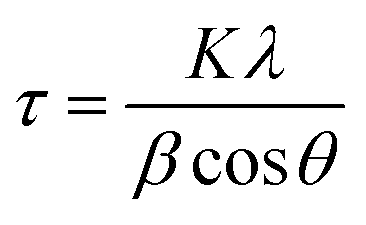
In Fig. 1 is shown the X-ray diffraction (XRD) pattern obtained from NiO nanoparticles synthesized in this work. The diffraction peaks have been identified to be those pertaining to NiO crystals.10 Using Debye–Scherrer equation42 viz.,| |
 | (1) |
where, τ is the mean size of crystallites, λ the X-ray wavelength, β the line broadening at half the maximum intensity and θ the Bragg diffraction angle. A value of 19.9 nm was calculated as the mean particle size of NiO.
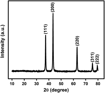 |
| | Fig. 1 X-ray diffractogram of NiO nanoparticles. | |
Fig. 2(a) is the transmission electron micrograph (TEM) of NiO nanoparticle prepared in the present work. Fig. 2(b) shows the high resolution view of Fig. 2(a) which exhibits clear view of NiO lattices confirming the crystalline nature. The particle size measured from Fig. 2(b) is about 19.2 nm. The particle size distribution obtained from Fig. 2(a) is shown in Fig. 2(c). The size distribution curve was fitted by a log normal profile which is shown by a solid line in Fig. 2(c). The average particle size obtained from the histogram is in satisfactory agreement with that estimated from the X-ray line broadening result and the value was calculated to be 19.5 nm.48 Fig. 2(b) also shows the lattice fringes for the (111) planes of NiO. The d-spacing value for (111) plane is 2.42 Å which is in good agreement with other reported results.49,50 The XRD patterns as well as the fringes in the TEM are identical. The Selected Area Electron Diffraction (SAED) pattern obtained from TEM image is shown in Fig. 2(d). The rings in SAED pattern were indexed with corresponding calculated d-spacing values of all the spots to consistent (hkl) planes shown in the image. The d-spacing values for planes (111), (200) and (220) are 2.42 Å, 2.09 Å and 1.48 Å respectively. These values are identical with cubic structure of NiO material (JCPDS no. 75-0197).50
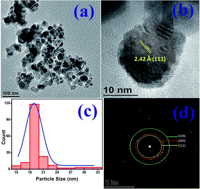 |
| | Fig. 2 (a) Transmission electron micrograph of NiO nanoparticles. (b) High resolution view of (a). (c) Particle size distribution obtained from (a). Solid lines are representing the fitting of size distribution curve. (d) Electron diffraction pattern obtained from sample. | |
Fig. 3(a) shows the X-ray photoelectron spectroscopy (XPS) spectra for NiO nanoparticles. The peaks of Ni 2p3/2, Ni 2p3/2 satellite, Ni 2p1/2, and Ni 2p1/2 satellite at 853.88 eV, 860.91 eV, 872.85 eV and 879.52 eV respectively confirm the presence of Ni in the material.51 An additional shoulder near 855.78 eV has been ascribed to the presence of defect sites.52 Ni 2p3/2 peak was deconvoluted and the asymmetric Gaussian peak was fitted using PeakFit software with two symmetrical peaks at around 853.7 eV and 855.8 eV. Those peak positions were matched with that of Ni2+ 2p3/2 and Ni3+ 2p3/2 respectively.51–53 The relative amounts of Ni2+ and Ni3+ species were obtained53 from the ratios of the areas under the two peaks and the values are 0.69 and 0.31 respectively. This is shown in Fig. 3(b).51 The formation of Ni2+ ions are the most obvious defects in NiO.51,54–58 It was also confirmed from the XPS spectra of oxygen. The O 1s spectra shown in Fig. 3(c) was deconvoluted into three peaks. The peaks at 529.40 eV (low binding energy), 531.09 eV (mid binding energy) and 532.10 eV (high binding energy) correspond to surface hydroxyl, oxygen bonds with Ni2+ and Ni3+ respectively. So, the mid binding energy corresponds to the oxygen vacancy which is leading to the formation of Ni2+ ions in NiO nanoparticles.50,51,59–63 This deficiency of oxygen ions was created during synthesis process.64
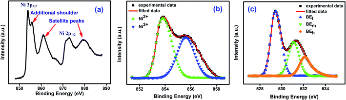 |
| | Fig. 3 (a) XPS spectrum of Ni obtained from NiO nanoparticles. (b) Deconvolution of Ni 2p3/2 into peaks at 853.7 eV and 855.8 eV. (c) XPS spectrum of O and deconvolution of O into peaks at 529.40 eV, 531.09 eV and 532.10 eV. | |
The presence of both Ni2+ and Ni3+ ions affect the electrical properties of as synthesized NiO nanoparticles as discussed below. Two adjacent Ni2+ ions transformed into Ni3+ ions to achieve charge neutrality due to presence of Ni2+ vacancy.65 Among them each Ni2+ with two Ni3+ ions constitute a bound quadrupole.65 In a quadrupole when a Ni2+ ion transfers a 3d electron to adjacent Ni3+ a hole is formed with lattice distortion. This distortion associated with holes establishes small polaron in the localized 3d band of Ni2+.48,65–67 Those small polarons conduct at temperatures above 100 K employing thermally activated polarons.65,68,69 On the other hand, when O2− ion transfers a 2p electron, a hole is formed in the 2p band of O2− which creates a large polaron associated with lattice distortion. So, both polaronic hopping give rise to conductivity in NiO.65
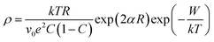
As discussed earlier, the presence of both Ni2+ and Ni3+ ions lead to conductivity in the as synthesized NiO nanoparticles. The conductivity in this material is ascribed to small polaron hopping mechanism between Ni2+ and Ni3+ sites.70,71 The variation of log![[thin space (1/6-em)]](https://www.rsc.org/images/entities/char_2009.gif) DC resistivity as a function of inverse temperature (T) of a pellet comprising of NiO nanoparticles is shown in Fig. 4. The DC resistivity data have therefore been analysed by the following equation,70,71
DC resistivity as a function of inverse temperature (T) of a pellet comprising of NiO nanoparticles is shown in Fig. 4. The DC resistivity data have therefore been analysed by the following equation,70,71
| |
 | (2) |
where,
k is the Boltzmann constant,
T is the temperature,
R is the average site separation between the two sites,
v0 is the optical phonon frequency,
e is the electronic charge,
α is the spatial decay parameter for the electronic wave function characterizing the localized state at each of the Ni sites,
C is the ratio of Ni
2+/(total Ni concentration) and
W is the activation energy. The activation energy
W was calculated from the slope of the straight line shown in
Fig. 4. This was found to be 0.4 eV. By fitting the resistivity data to
eqn (2) taking
R,
α and
v0 as fitting parameters we obtained their values as summarized in
Table 1. These values are consistent with previously reported result.
10
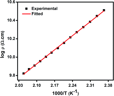 |
| | Fig. 4 DC resistivity (ρ) as a function of inverse temperature (T−1) for NiO nanoparticles, where solid lines represent the theoretical fits to small polaron hopping conduction model. | |
Table 1 Parameters obtained by fitting the data to eqn (2)
| NiO nanoparticle compact |
C |
W (eV) |
R (Å) |
α (Å−1) |
v0 (s−1) |
| |
0.69 |
0.40 |
5.2 |
0.89 |
3.8 × 10¹³ |
Fig. 5 gives the variation of magnetization as a function of temperature for NiO nanoparticles under both zero-field cooled (ZFC) and field-cooled (FC) conditions by applying a magnetic field of 50 Oe in the temperature range 2–300 K. In the FC plot the magnetization data show increasing behaviour in the low temperature range with shoulder like nature at 25 K. It can be seen that there is a divergence between FC and ZFC plots i.e., bifurcation temperature (TB) at 300 K indicating all spins are unblocked above this temperature, a freezing temperature (TF) at 9 K in the ZFC plot indicating irreversibility of magnetization under FC and ZFC conditions and a broad region at 215 K below TB indicating thermal relaxation of the uncompensated spins. A spin-glass like state is thus apparent due to the sharp peak at TF for the system. These peaks have similarity with other reported results.72–75 They will be shifted to lower temperature with decreasing particle size.76 This is believed to lead to a large magnetodielectric effect in this material as shown later.
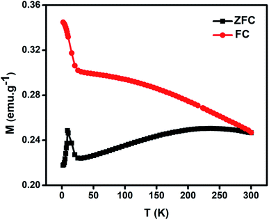 |
| | Fig. 5 Magnetization (M) variation as a function of temperature (T) for NiO nanoparticles under field-cooled (FC) and zero-field cooled (ZFC) conditions. | |
Fig. 6 gives the variation of magnetization (M) vs. magnetic field (H) at different temperatures of NiO nanoparticles. The maximum values of M obtained here is much higher than other reported results.10,77,78 The oxygen vacancies formed at the surface increases the magnetization in the system. Inset shows the magnified form of the curves to give the coercivity values. High magnetization is the result of presence of Ni3+ ions which causes uncompensated magnetic spins in the antiferromagnetic phase of NiO nanoparticles. Those uncompensated magnetic spins give significant contribution to the ferromagnetic like behaviour. Thus, there is a magnetic interaction between ferromagnetic and antiferromagnetic phases at the interface.78 Pure NiO powder possess antiferromagnetism with linear nature at higher fields and no remanence magnetization and coercivity at lower field.79 In this as synthesized nanoparticles at higher fields the non-saturating nature of the M–H curve gives antiferromagnetic like behaviour, whereas at lower fields the higher value of magnetization gives the ferromagnetic like behaviour confirming the presence of ferromagnetism.80 So, structural defects like presence of both Ni2+ and Ni3+ ions modified the magnetic behaviour which introduced finite magnetic moment in antiferromagnetic NiO and induced ferromagnetism.
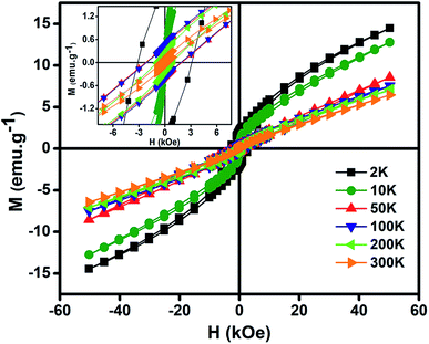 |
| | Fig. 6 Variation of magnetization (M) as a function of magnetic field (H) at different temperatures for NiO nanoparticles. (Inset) magnified view of magnetization (M) vs. magnetic field (H) curve. | |
Fig. 7(a) and (b) give the variations of real (ε′) and imaginary (ε′′) parts respectively of dielectric permittivity of NiO nanoparticle compact at frequencies in the range 20 Hz to 2 MHz. The magnetodielectric parameter (MD) was calculated using the relation
| |
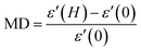 | (3) |
where,
ε′(
H) is the real part of dielectric permittivity at an applied magnetic field
H,
ε′(0) is the real part of dielectric permittivity with no applied magnetic field. The magnetodielectric parameters as calculated from the data are summarised in
Table 2.
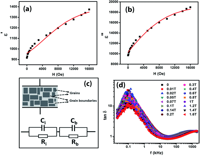 |
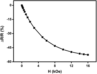
| | Fig. 7 Variation of (a) real part (ε′) and (b) imaginary part (ε′′) of dielectric permittivity as a function of magnetic field for NiO nanoparticles at 20 Hz frequency. The solid lines represent the theoretical fits to Catalan's model. (c) The schematic representation of the configuration containing grain and depleted grain boundaries giving rise to magnetodielectric effect and the equivalent circuit diagram of Maxwell–Wagner behaviour. (d) Variation of dielectric loss (tanδ) as a function of log frequency for different magnetic fields for NiO nanoparticles. | |
Table 2 Magnetodielectric parameters for NiO nanoparticles at different frequencies
| Frequency |
MD parameter |
| 20 Hz |
52.2 |
| 100 kHz |
15.91 |
| 2 MHz |
24 |
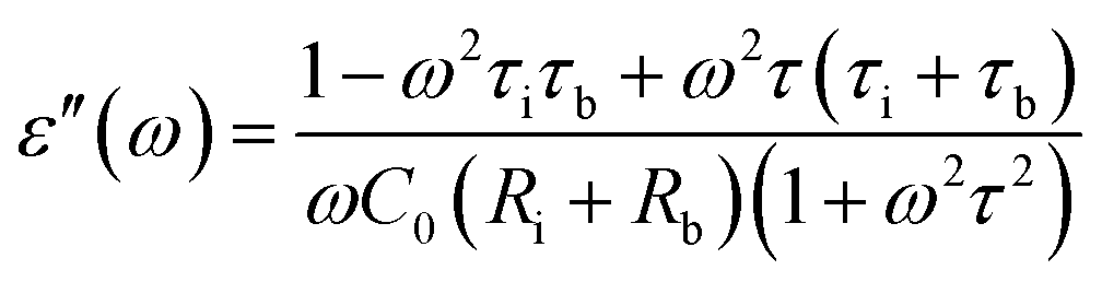
It can be seen that the MD parameters at these frequencies show an increase up to 52.2% when the magnetic field applied is 1.6 tesla. This is quite large. We have analysed these results applying Catalan's model which is based on Maxwell–Wagner polarization arising out of two dielectric materials with different values of resistivities in series forming an interface which leads to a space charge polarization.40 It has been shown that the above model leads to the following equations for the real and imaginary parts of the dielectric permittivity viz.,
| |
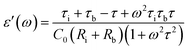 | (4) |
| |
 | (5) |
where,
 A
A is the specimen area,
t its thickness,
ε0 is the free space dielectric permittivity,
Ri is the resistance of the interfacial dielectric and
Rb is the resistance of the NiO nanoparticles,
| τi = CiRi, Ci is the capacitance of the interfacial dielectric, |
| τb = CbRb, Cb is the capacitance of the NiO nanoparticles, |
The Maxwell–Wagner behaviour with grain and depleted grain boundaries is schematically represented in Fig. 7(c) and the equivalent circuit diagram consisting of two C–R circuits (Ci, Ri, Cb, Rb) in series connection is also shown in Fig. 7(c) to represent Catalan's model.
The experimental data shown in Fig. 7(a) and (b) were fitted to eqn (4) and (5) by assuming a negative magnetoresistance in NiO with a variation with magnetic field given by 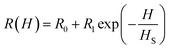 in which R0, R1 and HS were fitting parameters. The solid lines in Fig. 7(a) and (b) represent the theoretical fits. Fig. 7(d) shows the variation of dielectric loss tanδ as a function of log frequency for different magnetic fields. The extracted values of the relative changes of the resistance of the NiO nanoparticles as a function of magnetic field are given in Fig. 8. The resistance change at a magnetic field of 1.6 tesla is around 52.5% at frequency 20 kHz. It is seen that the magnetodielectric parameter decreases to 15.91% at 100 kHz and subsequently increases to 24% at 2 MHz. This can be explained on the basis of Maxwell–Wagner polarization in the present system. The above mechanism occurs at the interfaces of the NiO nanoparticles as also in between the sample–electrode interface. The relaxation time for the former will be larger than that of the latter keeping in view the product of the equivalent capacitance and resistance of the above two mechanisms. The value of the latter will be smaller thereby giving rise to a dielectric loss peak at a frequency higher than that for the former. This is consistent with the experimental results obtained and shown in Fig. 7(d). The lowering of resistivity in all our samples as a function of applied magnetic field is ascribed to the enhancement of spin polarized electron hopping between the localized states represented by Ni2+ and Ni3+ sites in the NiO nanoparticles.
 |
| | Fig. 8 Variation of extracted values of percentage change of resistance  as a function of applied magnetic field (H) for NiO nanoparticles at frequency 20 kHz. as a function of applied magnetic field (H) for NiO nanoparticles at frequency 20 kHz. | |
We have carried out direct measurements on the change of resistance as a function of applied magnetic field on our samples of compacted NiO nanoparticles as described before. The result is shown in Fig. 9. The resistance variation is found to be similar with Fig. 8 in nature though there is a little mismatch for higher values of applied magnetic field. This is ascribed to the difference between the actual geometrical configuration of the NiO sample and the ideal one assumed in Catalan's model.
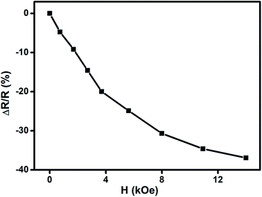 |
| | Fig. 9 Change of resistance  as a function of applied magnetic field (H) for NiO nanoparticles at room temperature as measured directly. as a function of applied magnetic field (H) for NiO nanoparticles at room temperature as measured directly. | |
Magnetoresistance arises due to the magnetic scattering caused by the spin fluctuations of the localised spins during the application of magnetic field.81 In general, antiferromagnetic materials show positive magnetoresistance i.e., magnetic field increases spin fluctuations, whereas paramagnetic and ferromagnetic materials show negative magnetoresistance i.e., magnetic field suppresses spin fluctuations which help to reduce the resistance of materials.81,82 In few cases magnetoresistance may be zero, thus values of magnetoresistance depend upon the sum of spin fluctuations. In this material there is an interaction between ferromagnetic and antiferromagnetic phases which leads to ferromagnetic behaviour because of the magnetic field suppressing the spin fluctuations in one sub lattice if we consider two sub lattices made up of Ni2+ and Ni3+ ions. Thus, negative magnetoresistance appears in NiO nanoparticles. In this case the value of negative magnetoresistance is ∼37% at room temperature which is much higher than other reported results.83–85 In the latter cases, carbon coated NiO nanoparticles were present which helped to contribute to tunnelling between the grains but in the present work undoped NiO nanoparticles are giving higher magnetoresistance which can be extremely important for magnetic device applications.
Conclusions
In summary, NiO nanoparticles with a diameter of around 19.5 nm were synthesized by a simple chemical route. Low temperature magnetization measurements indicated this had spin-glass behaviour. The compacted NiO nanoparticles showed electronic conduction which arose because of the presence of Ni2+ and Ni3+ species in the material and the resulting small polaron hopping between these sites. The materials exhibited large magnetodielectric parameter of a maximum of 52.2% at room temperature. This is explained as arising due to a substantial negative magnetoresistance due to spin polarized electron hopping between Ni2+ and Ni3+ sites thereby causing space charge polarization. This was substantiated by direct measurement of magnetoresistance which gave identical results. The higher value of direct magnetoresistance than other reported results will make the material useful as a good magnetic sensor.
Conflicts of interest
There are no conflicts to declare.
Acknowledgements
S. Chatterjee acknowledges the award of INSPIRE Fellowship by DST, New Delhi. D. Chakravorty thanks DST, New Delhi for the award of SERB Distinguished Fellowship and INSA, New Delhi for giving him an Emeritus Scientist position.
References
- N. Srivastava and P. C. Srivastava, Phys. E, 2010, 42, 2225 CrossRef CAS.
- Y. N. Xia, P. D. Yang, Y. G. Sun, Y. Y. Wu, B. Mayers, B. Gates, Y. D. Yin, F. Kim and H. Q. Yan, Adv. Mater., 2003, 15, 353 CrossRef CAS.
- K. J. Klabunde, J. Stark, O. Koper, C. Mohs, G. P. Dong, S. Decker, Y. Jiang, I. Lagadic and D. Zhang, J. Phys. Chem., 1996, 100, 12142 CrossRef CAS.
- C. K. Choo, T. L. Goh, L. Shahcheraghi, G. C. Ngoh, A. Z. Abdullah, B. A. Horri and B. Salamatinia, J. Am. Ceram. Soc., 2016, 99, 3874 CrossRef CAS.
- K. Song, J. Zhou, J. Bao and Y. Feng, J. Am. Ceram. Soc., 2008, 91, 1369 CrossRef CAS.
- J. Park, E. Kang, S. U. Son, H. M. Park, M. K. Lee, J. Kim, K. W. Kim, H. J. Noh, J. H. Park, C. J. Bae, J. G. Park and T. Hyeon, Adv. Mater., 2005, 17, 429 CrossRef CAS.
- J. A. Dirksen, K. Duval and T. A. Ring, Sens. Actuators, B, 2001, 80, 106 CrossRef CAS.
- H. Steinebach, S. Kannan, L. Reith and F. Solzbacher, Sens. Actuators, B, 2010, 151, 162 CrossRef CAS.
- A. C. Sonavane, A. I. Inamdar, P. S. Shinde, H. P. Deshmukh, R. S. Patil and P. S. Patil, J. Alloys Compd., 2010, 489, 667 CrossRef CAS.
- S. Chatterjee, R. P. Maiti, M. Miah, S. K. Saha and D. Chakravorty, ACS Omega, 2017, 2, 283 CrossRef CAS PubMed.
- X. Wang, L. Li, Y. G. Zhang, S. T. Wang, Z. D. Zhang, L. F. Fei and Y. T. Qian, Cryst. Growth Des., 2006, 6, 2163 CrossRef CAS.
- M. C. A. Fantini, F. F. Ferreira and A. Gorenstein, Solid State Ionics, 2002, 152–153, 867 CrossRef CAS.
- J. Bandara and H. Weerasinghe, Sol. Energy Mater. Sol. Cells, 2005, 85, 385 CrossRef CAS.
- X. Wang, J. M. Song, L. S. Gao, J. Y. Jin, H. G. Zheng and Z. D. Zhang, Nanotechnology, 2005, 16, 37 CrossRef CAS.
- Y. R. Park and K. J. Kim, J. Cryst. Growth, 2003, 258, 380 CrossRef CAS.
- Y. D. Wang, C. L. Ma, X. D. Sun and H. D. Li, Inorg. Chem. Commun., 2002, 5, 751 CrossRef CAS.
- S. A. Needham, G. X. Wang and H. K. Liu, J. Power Sources, 2006, 159, 254 CrossRef CAS.
- A. H. Lu, E. L. Salabas and F. Schüth, Angew. Chem., Int. Ed., 2007, 46, 1222 CrossRef CAS PubMed.
- M. A. Morales, R. Skomski, S. Fritz, G. Shelburne, J. E. Shield, M. Yin, S. O'Brien and D. L. Leslie-Pelecky, Phys. Rev. B: Condens. Matter Mater. Phys., 2007, 75, 134423 CrossRef.
- L. Néel, Ann. Geophys., 1949, 5, 99 Search PubMed.
- W. F. Brown Jr, Phys. Rev., 1963, 130, 1677 CrossRef.
- M. Ghosh, K. Biswas, A. Sundaresana and C. N. R. Rao, J. Mater. Chem., 2006, 16, 106 RSC.
- J. F. K. Cooper, A. Ionescu, R. M. Langford, K. R. A. Ziebeck, C. H. W. Barnes, R. Gruar, C. Tighe, J. A. Darr, N. T. K. Thanh and B. Ouladdiaf, J. Appl. Physiol., 2013, 114, 083906 CrossRef.
- Y. Ichiyanagia, N. Wakabayashia, J. Yamazakia, S. Yamadaa, Y. Kimishimaa, E. Komatsub and H. Tajimab, Phys. B, 2003, 329–333, 862 CrossRef.
- M. Ghosh, K. Biswas, A. Sundaresana and C. N. R. Rao, J. Mater. Chem., 2006, 16, 106 RSC.
- A. E. Berkowitz and K. Takano, J. Magn. Magn. Mater., 1999, 200, 552 CrossRef CAS.
- J. T. Richardson and W. O. Milligan, Phys. Rev., 1956, 102, 1289 CrossRef CAS.
- M. Tadic, M. Panjan, D. Markovic, B. Stanojevic, D. Jovanovic, I. Milosevic and V. Spasojevic, J. Alloys Compd., 2014, 586, S322 CrossRef CAS.
- D. Y. Jiang, J. M. Qin, X. Wang, S. Gao, Q. C. Liang and J. X. Zhao, Vacuum, 2012, 86, 1083 CrossRef CAS.
- H. Duan, X. Zheng, S. Yuan, Y. Li, Z. Tian, Z. Deng and B. Su, Mater. Lett., 2012, 81, 245 CrossRef CAS.
- M. A. Subramanian, T. He, J. Chen, N. S. Rogado, G. T. Calvarese and W. A. Sleight, Adv. Mater., 2006, 18, 1737 CrossRef CAS.
- T. Bonaedy, Y. S. Koo, K. D. Sung and J. H. Jung, Appl. Phys. Lett., 2007, 91, 132901 CrossRef.
- P. Liu, Z. X. Cheng, Y. Du and X. L. Wang, J. Phys. D: Appl. Phys., 2010, 43, 325002 CrossRef.
- Z. X. Cheng, H. Shen, J. Y. Xu, P. Liu, S. J. Zhang, J. L. Wang, X. L. Wang and S. X. Dou, J. Appl. Phys., 2012, 111, 034103 CrossRef.
- L. Yan, Z. Xing, Z. Wang, G. Lei, J. Li and D. Viehland, Appl. Phys. Lett., 2009, 94, 192902 CrossRef.
- Y. S. Koo, T. Bonaedy, K. D. Sung, J. H. Jung, J. B. Yoon, Y. H. Jo, M. H. Jung, H. J. Lee, T. Y. Koo and Y. H. Jeong, Appl. Phys. Lett., 2007, 91, 212903 CrossRef.
- S. Dong, Y. Hou, Y. Yao, Y. Yin, D. Ding, Q. Yu and X. Li, J. Am. Ceram. Soc., 2010, 93, 3814 CrossRef CAS.
- L. Y. Wang, Q. Li, Y. Y. Gong, D. H. Wang, Q. Q. Cao and Y. W. Du, J. Am. Ceram. Soc., 2014, 97, 2024 CrossRef CAS.
- Y. Q. Lin and X. M. Chen, J. Am. Ceram. Soc., 2011, 94, 782 CrossRef CAS.
- G. Catalan, Appl. Phys. Lett., 2006, 88, 102902 CrossRef.
- M. M. Parish and P. B. Littlewood, Phys. Rev. Lett., 2008, 101, 166602 CrossRef PubMed.
- B. D. Cullity and S. R. Stock, Elements of X-ray Diffraction, Prentice Hall Inc, 3rd edn, 2001, pp. 167–171 Search PubMed.
- G. H. Yu, F. W. Zhu and C. L. Chai, Appl. Phys. A, 2003, 76, 45 CrossRef CAS.
- K. Chahara, T. Ohno, M. Kasai and Y. Kozono, Appl. Phys. Lett., 1993, 63, 1990 CrossRef CAS.
- R. von Helmolt, J. Wocker, B. Holzapfel, M. Schultz and K. Samwer, Phys. Rev. Lett., 1993, 71, 2331 CrossRef CAS PubMed.
- S. Jin, T. H. Tiefel, M. McCormack, R. A. Fastnacht, R. Ramesh and L. H. Chen, Science, 1994, 264, 413 CrossRef CAS PubMed.
- S. Chakrabarty and K. Chatterjee, J. Phys. Sci., 2009, 13, 245 Search PubMed.
- G. Madhu, V. C. Bose, A. S. Aiswaryaraj, K. Maniammal and V. Biju, Colloids Surf., A, 2013, 429, 44 CrossRef CAS.
- S. Rakshit, S. Ghosh, S. Chall, S. S. Mati, S. P. Moulik and S. C. Bhattacharya, RSC Adv., 2013, 3, 19348 RSC.
- S. Rajendran, D. Manoj, K. Raju, D. D. Dionysiou, M. Naushad, F. Gracia, L. Cornejo, M. A. Gracia-Pinilla and T. Ahamad, Sens. Actuators, B, 2018, 264, 27 CrossRef CAS.
- R. Peng, K. Shrestha, G. Mishra, J. Baltrusaitis, C.-M. Wu and R. T. Koodali, RSC Adv., 2016, 6, 59169 RSC.
- M. W. Roberts and R. S. C. Smart, J. Chem. Soc., Faraday Trans. 1, 1984, 80, 2957 RSC.
- W. C. Cheng and Y. C. Fu, Nanoscale Res. Lett., 2013, 8, 33 CrossRef PubMed.
- Y. Zhang, Y. Wang, J. Jia and J. Wang, Sens. Actuators, B, 2012, 171–172, 580 CrossRef CAS.
- P. Yang, X. Tong, G. Wang, Z. Gao, X. Guo and Y. Qin, ACS Appl. Mater. Interfaces, 2015, 7, 4772 CrossRef CAS PubMed.
- Z. Da Gao, Y. Han, Y. Wang, J. Xu and Y. Y. Ong, Sci. Rep., 2013, 3, 3323 CrossRef PubMed.
- Z. W. Pan, Science, 2001, 291, 1947 CrossRef CAS PubMed.
- L. G. Devi, N. Kottam, B. N. Murthy and S. G. Kumar, J. Mol. Catal. A: Chem., 2010, 328, 44 CrossRef CAS.
- N. K. Shrestha, M. Yang, Y. C. Nah, I. Paramasivam and P. Schmuki, Electrochem. Commun., 2010, 12, 254 CrossRef CAS.
- D. Wang, Z.-H. Zhou, H. Yang, K.-B. Shen, Y. Huang and S. Shen, J. Mater. Chem., 2012, 22, 16306 RSC.
- X. Wang and T. T. Lim, Water Res., 2013, 47, 4148 CrossRef CAS PubMed.
- S. Wang, H. Qian, Y. Hu, W. Dai, Y. Zhong, J. Chen and X. Hu, Dalton Trans., 2013, 42, 1122 RSC.
- K. Sivaranjani and C. S. Gopinath, J. Mater. Chem., 2011, 21, 2639 RSC.
- L. Qiao and X. Bi, Europhys. Lett., 2011, 93, 57002 CrossRef.
- D. Adler and J. Feinleib, Phys. Rev. B: Solid State, 1970, 2, 3112 CrossRef.
- V. Biju and M. A. Khadar, Mater. Res. Bull., 2001, 36, 21 CrossRef CAS.
- G. Madhu, V. C. Bose, K. Maniammal, A. S. Aiswaryaraj, K. Maniammal and V. Biju, Phys. B, 2013, 421, 87 CrossRef CAS.
- D. P. Snowden and H. Saltzburg, Phys. Rev. Lett., 1965, 14, 497 CrossRef CAS.
- P. Lunkenheimer, A. Loidl, C. R. Ottermann and K. Bange, Phys. Rev. B: Condens. Matter Mater. Phys., 1991, 44, 5927 CrossRef CAS PubMed.
- N. F. Mott, J. Non-Cryst. Solids, 1968, 1, 1 CrossRef CAS.
- I. G. Austin and N. F. Mott, Adv. Phys., 1969, 18, 41 CrossRef CAS.
- E. Winkler, R. D. Zysler, M. V. Mansilla, D. Fiorani, D. Rinaldi, M. Vasilakaki and K. N. Trohidou, Nanotechnology, 2008, 19, 185702 CrossRef CAS PubMed.
- S. Thota and J. Kumar, J. Phys. Chem. Solids, 2007, 68, 1951 CrossRef CAS.
- F. H. Aragón, P. E. N. de Souza, J. A. H. Coaquira, P. Hidalgo and D. Gouvêa, Phys. Rev. B: Condens. Matter Mater. Phys., 2012, 407, 2601 CrossRef.
- S. Mandal, K. S. R. Menon, S. K. Mahatha and S. Banerjee, Appl. Phys. Lett., 2011, 99, 232507 CrossRef.
- W. J. Duan, S. H. Lu, Z. L. Wu and Y. S. Wang, J. Phys. Chem. C, 2012, 116, 26043 CrossRef CAS.
- S. Brems, D. Buntinx, K. Temst, C. V. Haesendonck, F. Radu and H. Zabel, Phys. Rev. Lett., 2005, 95, 157202 CrossRef PubMed.
- L. G. Wang, C. M. Zhu, D. L. G. C. Bao, Z. M. Tian and S. L. Yuan, J. Mater. Sci., 2015, 50, 5904 CrossRef CAS.
- P. Ravikumar, B. Kisan and A. Perumal, AIP Adv., 2015, 5, 087116 CrossRef.
- E. Winkler, R. D. Zysler, M. V. Mansilla and D. Fiorani, Phys. Rev. B: Condens. Matter Mater. Phys., 2005, 72, 132409 CrossRef.
- H. Yamada and S. Takada, J. Phys. Soc. Jpn., 1973, 34, 51 CrossRef CAS.
- H. Yamada and S. Takada, Prog. Theor. Phys., 1972, 48, 1828 CrossRef CAS.
- L. D. Bianco, F. Boscherini, A. L. Fiorini, M. Tamisari, F. Spizzo, M. V. Antisari and E. Piscopiello, Phys. Rev. B: Condens. Matter Mater. Phys., 2008, 77, 094408 CrossRef.
- S. V. Pol, V. G. Pol, A. Frydman, G. N. Churilov and A. Gedanken, J. Phys. Chem. B, 2005, 109, 9495 CrossRef CAS PubMed.
- M. Patange, S. Biswas, A. K. Yadav, S. N. Jha and D. Bhattacharyya, Phys. Chem. Chem. Phys., 2015, 17, 32398 RSC.
|
| This journal is © The Royal Society of Chemistry 2020 |
Click here to see how this site uses Cookies. View our privacy policy here. 
 Open Access Article
 This Open Access Article is licensed under a Creative Commons Attribution-Non Commercial 3.0 Unported Licence
 *a
*a


 A is the specimen area, t its thickness, ε0 is the free space dielectric permittivity, Ri is the resistance of the interfacial dielectric and Rb is the resistance of the NiO nanoparticles,
 in which R0, R1 and HS were fitting parameters. The solid lines in Fig. 7(a) and (b) represent the theoretical fits. Fig. 7(d) shows the variation of dielectric loss tan
 as a function of applied magnetic field (H) for NiO nanoparticles at frequency 20 kHz.
 as a function of applied magnetic field (H) for NiO nanoparticles at room temperature as measured directly.