DOI:
10.1039/C9RA10579D
(Paper)
RSC Adv., 2020,
10, 4916-4926
Effects of bleaching and functionalization of kaolinite on the mechanical and thermal properties of polyamide 6 nanocomposites
Received
16th December 2019
, Accepted 8th January 2020
First published on 29th January 2020
Abstract
Polyamide 6 nanocomposites (PA6)/kaolinite were prepared by melt compounding. First, kaolinite was bleached via a solvothermal reaction using oxalic acid as a bleaching agent; then, the bleached product was modified using dimethylsulfoxide (DMSO) and subsequently methanol (MeOH) via a displacement method. Thus, cetyltrimethyl ammonium bromide (CTAB) and triethoxy(octyl)silane (TEOS) molecules were intercalated into kaolinite nano-platelets. Seven types of nanocomposites were prepared using pristine, bleached or intercalated kaolinite. The kaolinite powder and the nanocomposite specimens were characterized by X-ray diffraction (XRD), Fourier transformation infrared spectroscopy (FTIR), thermal analysis, scanning electronic microscopy (SEM), whiteness index and tensile tests. The influence of the bleaching process of kaolinite and the intercalation methods on the whiteness index of the nanocomposites was also observed, in which the whiteness index of the functionalized kaolinite nanocomposites was enhanced by up to 10.65% when compared to neat PA6. The thermal results revealed that the intercalation and functionalization greatly affect the thermal stability of the virgin polymer. On the other hand, the intercalation of kaolinite enhances the dispersion/distribution, improves the interfacial adhesion, and increases the aspect ratio of the kaolinite nanoparticles; this affords remarkable nanocomposite property enhancements, represented by a high Young's modulus value of 4.68 GPa and a maximum percentage growth of 80.6% for silane-grafted kaolinite nanoparticles at just 8 wt%.
Introduction
Polyamide 6 (PA6) is an important semi-crystalline polyamide that is commonly used in numerous applications, such as automotive components, sports equipment, electric/electronic equipment, packaging, textiles, power tool housings, and gears, due to its higher impact toughness, high crystalline melting point, good resistance to solvents, high strength, ease of processing, high wear resistance and superior elongation at break. However, some intrinsic disadvantages, such as decreased tensile strength and lower flexural modulus, restrict its field of applications.1 Since the first results obtained by Toyota Research in 1993, the dispersion of nanolayered clay (montmorillonite) in a polyamide 6 matrix has continued to attract much research attention worldwide in the field of nanocomposites consisting of PA6 and clay platelet reinforcements and/or other fillers to enhance the overall properties of the nanocomposites.2 The originality of this work is that nanocomposites with excellent thermo-mechanical properties are synthesized for the first time with functionalized bleached kaolinite through a solvothermal reaction followed by displacement.
Kaolin is a type of rock that contains clay mineral groups and is an industrial mineral commodity; the groups generally include kaolinite, halloysite, dickite, and nacrite.3 Amongst these four clay types, the most important is kaolinite because it is well-known for its good properties, including notably high whiteness or near whiteness, softness, fine particle size, lath-shaped and platy particles, low surface area and chemical inertness.4 Due to these properties, kaolinite is a versatile industrial mineral; it finds numerous applications as a coating and filler pigment for paper, a filler for paint, and in rubber, insecticides, medicine formulations, cosmetics, etc. It has also drawn the attention of researchers in the field of clay polymer nanocomposites.
Kaolinitic clay is dioctahedral, with the chemical formula Al2O3·2SiO2·2H2O; it consists of two types of layered aluminosilicate clay in a 1![[thin space (1/6-em)]](https://www.rsc.org/images/entities/char_2009.gif) :1 ratio. They are made of a gibbsite-type structure where each aluminum cations inhabits the center of an octahedron with six oxygen atoms and hydroxyl groups in the vertices, these units are covalently linked to the other layer, formed by silica-type structure, where each silicon atom occupying the center of a tetrahedron with oxygen atoms in the summits.5 Kaolin has multilayer walls with positively charged alumina faces, Al–OH functional groups on the inner surface, and negatively charged edges containing Si–OH functional groups on the outer surface. Due to these characteristics, kaolin is an excellent absorbent for both cationic and anionic molecules aimed at their chemical modification. In order to exfoliate the kaolinite layers, the hydroxy groups on the kaolinite surface could react with organic molecules; this changes the hydrophilic surface of the kaolin layers to organophilic, which allows polymer macromolecules to intercalate into the kaolin layers and form stable homogeneous structures.6
:1 ratio. They are made of a gibbsite-type structure where each aluminum cations inhabits the center of an octahedron with six oxygen atoms and hydroxyl groups in the vertices, these units are covalently linked to the other layer, formed by silica-type structure, where each silicon atom occupying the center of a tetrahedron with oxygen atoms in the summits.5 Kaolin has multilayer walls with positively charged alumina faces, Al–OH functional groups on the inner surface, and negatively charged edges containing Si–OH functional groups on the outer surface. Due to these characteristics, kaolin is an excellent absorbent for both cationic and anionic molecules aimed at their chemical modification. In order to exfoliate the kaolinite layers, the hydroxy groups on the kaolinite surface could react with organic molecules; this changes the hydrophilic surface of the kaolin layers to organophilic, which allows polymer macromolecules to intercalate into the kaolin layers and form stable homogeneous structures.6
As previously mentioned, pure kaolinite is white in color; however, the presence of small quantities of impurities may be sufficient to impart color to the ores. Examples include oxides, hydroxides and hydrated oxides of ferric iron, such as hematite (red), maghemite (reddish brown), goethite (brownish yellow), lepidocrocite (orange), and ferrihydrite (brownish red).7,8 The presence of these impurities negatively affects the thermal and optical properties of the ores, and it is one of the parameters that determines the quality of kaolinite. For this reason, it is necessary to remove or decrease the content of these impurities in pristine kaolinite by adopting numerous physical and chemical treatments, such as sieving, magnetic separation, froth flotation, selective flocculation, and biological and chemical leaching with various chemicals, such as oxalic acid and other organic acids.9 Amongst these, oxalic acid is the reagent of choice and a most effective bleaching agent because of its excellent ability to dissolve iron oxides, which leads to their relatively easy removal.10
The exfoliation of kaolinite in a polymer matrix leads to nanocomposites with enhanced properties compared to those of the starting inorganic and/or organic materials, such as increased strength, Young's modulus, and heat resistance as well as decreased gas permeability and flammability.11 In general, the morphology and size of kaolinite particles are important indices for the viscosity, plasticity, surface area and porosity volume of the kaolinite; this not only provides good reactivity towards the polymer matrix but also implies more homogeneous mixing during processing.11 Lattice expansion of kaolinite was used to achieve weakening of the interlayer van der Waals interactions and to form a network of hydrogen bonds between the kaolin layers, which is difficult to obtain directly with organic molecules. For this reason, there are only a few varieties of small and highly polar organic micro-molecules which can be used as precursors for synthesis via solvothermal reactions; examples include dimethylsulfoxide (DMSO), N-methylformamide (NMF), urea (U), aniline, hydrazine and potassium acetate.12 Amongst these, only DMSO organic solvent has the ability to intercalate directly because of its high dipole moment. Meanwhile, methanol (MeOH) is a polar guest species13 which can be used as a second expansion step to permit insertion; it is an effective intermediate of large, non-reactive molecules used in displacement intercalation methods.12
In this work, expansible kaolin was functionalized with cetyltrimethylammonium bromide (cationic surfactant) and triethoxy(octyl)silane (coupling agent) to transform the properties of kaolin from hydrophilic to organophilic and consequently to achieve better compatibility with non-polar matrices in the nanocomposites due to the nano-dispersion/distribution of fillers. Furthermore, the stronger interfacial interactions between the PA6 matrix and the fillers led to superior properties.
Experimental
Materials
The materials utilized were Ultramid polyamide 6 compound, which was obtained from O-BASF chemical company (density: 1.13 g mL−1 and melting temperature: 220 °C). Natural yellow kaolin typically forms by hydrothermal alteration of alkali granite of Oulmes, located in the center of the Moroccan Meseta, which contains kaolinite as the principal mineral and small quantities of quartz and illite. Other secondary mineral phases found in this yellow kaolin are iron oxides (goethite and/or hematite), resulting in a whiteness index of around 33.1%.45 The cetyltrimethyl ammonium bromide (CTAB), triethoxy(octyl)silane (TEOS), dimethylsulfoxide (DMSO), oxalic acid, sodium hydroxide (NaOH), and methanol (MeOH) used in this study were purchased from Sigma-Aldrich.
Methods
Purification of kaolinite. Kaolinite purification was performed in our laboratory according to the dispersion–decantation method.14 10 g kaolinite was suspended in 500 mL of water for 24 h. The suspension was filtered through a 100 μm sieve and dried at 110 °C for 24 h. Then, the material was crushed and sieved at 50 μm. The purified kaolinite is abbreviated as “KR.”
Bleaching process of kaolin. The oxalate leaching tests were carried out in a 1 L round bottomed flask with mechanical stirring in a heating mantle. A typical experiment proceeded as follows: the oxalate bleaching solution was prepared by dissolving 1.8 M oxalic acid in 400 mL of distilled water. The pH value of the solution was adjusted to 4 with sodium hydroxide (NaOH). Then, a sample of KR weighing 40 g was added to 400 mL of leaching solution at 90 °C for 2 h under high-intensity stirring. A Thermo Scientific Sorvall WX Floor Ultracentrifuge was used for solid–liquid separation of the bleached kaolinite sample (KB) at 10000 rpm for 20 min. The general dissolution reaction is shown in eqn (1):| | |
Fe3O4 + 8HC2O4− → 2FeIII(C2O4)33− + FeII(C2O4)22− + 4H2O
| (1) |
Preparation of DMSO-intercalated kaolinite. The preparation of the dimethylsulfoxide (DMSO)-intercalated kaolinite, labeled KD, was accomplished as follows: 180 mL of DMSO was dispersed well in distilled water with a volume ratio of 6:1. Then, kaolinite (30 g) was poured into the solution. The suspension was maintained under magnetic stirring for 12 h at 150 °C and was then allowed to stir for 12 h at room temperature. Subsequently, a Thermo Scientific Sorvall WX Floor Ultracentrifuge was used for solid–liquid separation of the sample at 10000 rpm for 20 min; the sample was washed 3 times using isopropanol to remove the excess DMSO. The product was dried at 60 °C for 24 h and then ground into powder for further use.
Preparation of MeOH-intercalated kaolinite. The intercalation of methoxy-modified kaolinite (KM) as a precursor was performed by adding 10 g of KD to a closed container that contained 40 mL methanol (MeOH). The suspension was stirred continuously at room temperature for 7 days. The solid in the mixture was successfully separated via centrifugation and dried at 60 °C for further use. The MeOH-intercalated kaolin was denoted as KM.
Functionalization of intercalated kaolinite. Chemical functionalization of the intercalated kaolinite was carried out in MeOH. Kaolinite (10 g) was first suspended at 25 °C through sonication for 30 min. Then, 10 mL of organic molecules (cetyltrimethyl ammonium bromide (CTAB) and triethoxy(octyl)silane (TEOS)) were added to the solution successively, and the reaction mixture was mechanically stirred for 24 h at 80 °C. Afterward, the solid was separated by centrifugation at 10000 rpm, washed using a mixture of acetone/water 3 times and dried at 60 °C under vacuum conditions. The two products are labeled as KC (cetyltrimethyl ammonium bromide) and KS (triethoxy(octyl)silane).
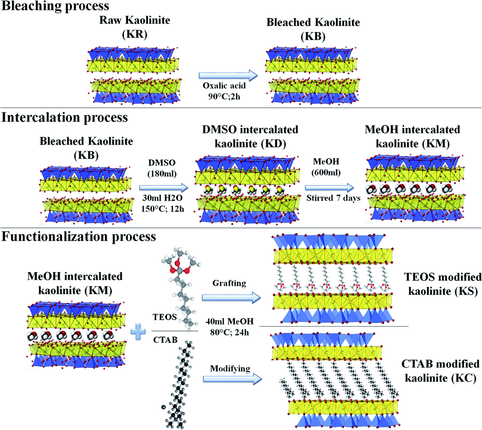
Preparation of PA6/kaolinite nano-composites. The PA6 nanocomposites with 8 wt% kaolinite filler loading were prepared in the molten state using a twin-screw micro-extruder (Thermo Scientific Haake Minilab Model II) at 220 °C with a screw speed of 80 rpm. The samples were then pelletized into granules of about 2 to 3 mm in length via a cutting mill (Thermo Fisher, UK). All the specimens were molded using a CARVER compression molding press into rectangle molds (100 × 70 × 1 mm3) with a clamping force of 15 tons, and the plate was heated to 220 °C as required in ASTM D4703 procedure C to prepare the nanocomposites.15 All process steps are summarized in Fig. 1.
 |
| | Fig. 1 Schematic of the chemical treatments of the kaolinite nanoparticles. | |
Characterization
X-ray diffraction (XRD). X-ray diffraction (XRD) was used to confirm the intercalation of the kaolinite clay. The data were recorded on a Bruker D8 Discover instrument using Cu Kα radiation (1.54184 nm) and a GADDS detector. The samples were consolidated in an aluminum holder and scanned at 45 kV from 0.5 to 90°. The diffraction patterns were analyzed using X'Pert High Score software. The interlayer distances of kaolinite were estimated from the WAXD patterns with the Bragg formula (eqn (2)):| | |
2dsinθ = nλ
| (2) |
The intercalation ratio used to evaluate the degree of intercalation reaction and it is estimated using eqn (3):
where
IK and
II are the intensities of the (001) diffractions of kaolinite and intercalated kaolinite, respectively.
Fourier transform infrared spectra (FTIR). Fourier transform infrared spectra (FTIR) of the pristine kaolinite powder as well as the bleached, treated and functionalized samples were obtained using an ABB Bomem FTLA 2000-102 spectrometer (ATR: Specac Golden Gate) via an accumulation of 16 scans with a resolution of 4 cm−1.
Thermogravimetric analysis (TGA). The thermal degradation of the kaolinite powder and the bleached, treated and functionalized samples was evaluated by thermal gravimetric analyses (TGA) recorded on a Q5000 (TA Instruments). Samples of about 30 mg were placed in platinum pans and heated under air from 50 °C to 850 °C at a heating rate of 10 °C min−1.
Differential scanning calorimetry (DSC). The measurements of the glass transition temperatures of the pristine kaolinite nanocomposites as well as the bleached, treated and functionalized samples were carried out using a Q100 from TA Instruments. Throughout the DSC studies, each sample (5 mg) of the polymers prepared by extrusion methods was encapsulated in an aluminum pan and placed in the holder to be heated, cooled, and heated repeatedly from 25 °C to 250 °C at a heating rate of 10 °C min−1. In order to calculate the value of the crystallinity index (Xc),14 the following equation was used:| |
 | (4) |
ΔHm: measured heating enthalpy. ΔH0m: theoretical value of the melting enthalpy at 100% crystallinity of PA6 (191 J g−1). (1 − ω): weight fraction of the polymer in the nanocomposite.
Scanning electron microscopy (SEM). To characterize the size and the morphology of the kaolinite particles, scanning electron microscopy (SEM-EDAX) was performed on an FEI Quattro S Environmental Scanning Electron Microscope (Thermo Fisher) operated at 20 kV and equipped with energy dispersive X-ray spectroscopy (EDS).
Whiteness index. The colors of the kaolin powder and the bleached, treated and functionalized samples were determined using a CM-700d/600d-Konica Minolta spectrophotometer according to Practices ASTM E 313-10.16 The samples with thick plaques (2 mm) and flattened surfaces were placed in the specimen measuring port.
Tensile testing. Tensile tests for five specimens of each nanocomposite were performed according to ISO 527-1:2012.17 The tests were performed on a Tinius Olsen H10KT universal testing machine at a crosshead speed of 5 mm min−1 using a 5 kN load cell. Tensile properties such as Young's modulus, tensile strength, and strain at yield of the composites were obtained from the stress–strain curves.
Results and discussion
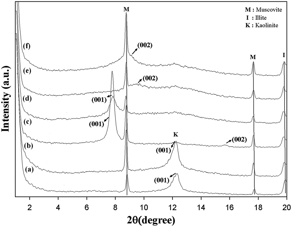
X-ray diffraction (XRD)
The X-ray diffractogram of intercalated kaolinite is compared to those of pristine and bleached kaolinite in Fig. 2. The XRD patterns of KR and KB are nearly identical, demonstrating that very little or no structural modification of the kaolinite arose during the bleaching process and that no crystalline secondary material was formed.18 The untreated and treated kaolinite samples display two peaks that are characteristic of muscovite at 2θ = 8.74 and 2θ = 17.64, corresponding to d = 10.11 Å and d = 5.03 Å, respectively.19 Another peak at 2θ = 19.74 corresponding to d = 4.5 Å is attributed to illite clay as an associated clay mineral.14 Finally, it can be observed that only the muscovite and illite minerals were detected by XRD as ancillary minerals, which are present in minor amounts in all kaolinite samples and arise from primary kaolin deposits; iron oxides such as magnetite (Fe3O4), hematite (Fe2O3), ferrous titanium oxide (Fe2TiO4), and greigite (Fe3S4) were not detectable because their concentrations in the kaolin samples are relatively low. Iron minerals are the main metal impurity in the kaolinite samples.
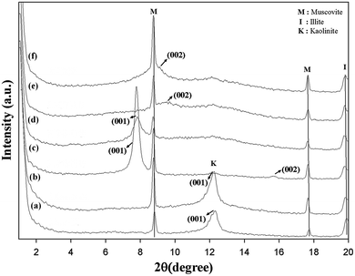 |
| | Fig. 2 Low-angle XRD patterns of (a) KR, (b) KB, (c) KD, (d) KM, (e) KC and (f) KS. | |
On the other hand, the 001 reflections of the pristine and bleached samples display broad bands in the region around 2θ = 12.28, corresponding to the interlayer spacing of 10.05 Å; this is assigned to the diffraction peaks (001) of kaolinite as the dominant mineralogical phase.20 However, the kaolinite treated with DMSO (KD) exhibits two reflections of (001) and (002), corresponding to diffraction values of d001 = 11.37 Å and d002 = 5.7 Å, respectively. The intercalation ratio (or degree of reaction) of the modified kaolinite by DMSO reached around 98.85%. This value confirms that the oxygen of the S![[double bond, length as m-dash]](https://www.rsc.org/images/entities/char_e001.gif) O group in DMSO is triply hydrogen bonded with the inner-surface hydroxyls of the gibbsite sheet of the kaolin layer, and one methyl group of DMSO is keyed into the ditrigonal hole in the tetrahedral sheet with the other S–C bond nearly parallel to the sheet.21 When pre-intercalate kaolinite was intercalated with MeOH in a recent attempt to replace the precursor (DMSO), the basal reflection in the dry state showed a d001 value (11.37 Å) nearly identical to that of DMSO-intercalated kaolinite, with an intercalation ratio of 85%. This may be due to the fact that the methoxy-modified inner surface resulted from the grafting of methanol molecules at the initial aluminol (AlOH) of the Al–O octahedron through the condensation to AlOMe groups between the hydroxyl groups of the two moieties, escaping the free methanol molecules from the interlayer space during a drying process.13 In the XRD patterns plotted in Fig. 2, the KC and KS samples clearly show (002) reflections at 2θ = 9.42 and 2θ = 8.92, corresponding to d002 values of 9.4 Å and 9.91 Å, respectively. These d-spacing increments indicate the successful intercalation of CTAB and TEOS molecules, breaking the hydrogen bonds between adjacent kaolinite layers and representing interlamellar expansions (obtained by subtracting the kaolinite c-spacings of Δd002 (KC) = 0.58 nm and Δd002 (KS) = 0.63 nm, respectively). This generally results in significant changes to the kaolinite surface properties (Table 1).
O group in DMSO is triply hydrogen bonded with the inner-surface hydroxyls of the gibbsite sheet of the kaolin layer, and one methyl group of DMSO is keyed into the ditrigonal hole in the tetrahedral sheet with the other S–C bond nearly parallel to the sheet.21 When pre-intercalate kaolinite was intercalated with MeOH in a recent attempt to replace the precursor (DMSO), the basal reflection in the dry state showed a d001 value (11.37 Å) nearly identical to that of DMSO-intercalated kaolinite, with an intercalation ratio of 85%. This may be due to the fact that the methoxy-modified inner surface resulted from the grafting of methanol molecules at the initial aluminol (AlOH) of the Al–O octahedron through the condensation to AlOMe groups between the hydroxyl groups of the two moieties, escaping the free methanol molecules from the interlayer space during a drying process.13 In the XRD patterns plotted in Fig. 2, the KC and KS samples clearly show (002) reflections at 2θ = 9.42 and 2θ = 8.92, corresponding to d002 values of 9.4 Å and 9.91 Å, respectively. These d-spacing increments indicate the successful intercalation of CTAB and TEOS molecules, breaking the hydrogen bonds between adjacent kaolinite layers and representing interlamellar expansions (obtained by subtracting the kaolinite c-spacings of Δd002 (KC) = 0.58 nm and Δd002 (KS) = 0.63 nm, respectively). This generally results in significant changes to the kaolinite surface properties (Table 1).
Table 1 2θ angles and basal spacings (d001, d002) of the intercalated kaolinite in relation to pristine kaolinite
| Sample |
2θ1 (degree) |
d001 (Å) |
2θ2 (degree) |
d002 (Å) |
| KR |
12.18 |
7.26 |
24.85 (ref. 13) |
3.6 (ref. 13) |
| KB |
12.24 |
7.23 |
24.85 (ref. 18) |
3.6 (ref. 18) |
| KD |
7.76 |
11.39 |
15.48 |
5.7 |
| KM |
7.77 |
11.37 |
20.64 (ref. 13) |
4.3 (ref. 13) |
| KS |
— |
— |
8.92 |
9.91 |
| KC |
— |
— |
9.42 |
9.4 |
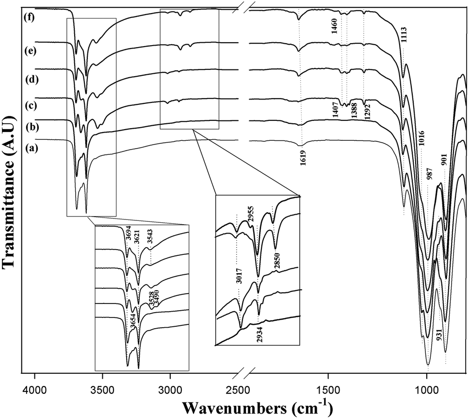
Structural characteristics (FTIR spectroscopy)
The FTIR spectrum of intercalated kaolinite is compared to those of pristine and bleached kaolinite in Fig. 3. For raw and bleached kaolinite, the transmittance bands at 3694 and 3621 cm−1 are ascribed to the stretches of inner-surface hydroxyl groups and to the vibrations of inner hydroxyl groups lying between the tetrahedral and octahedral sheets, respectively. Moreover, an additional weak band at 1619 cm−1 is due to the O–H bending vibration of water molecules. In the 1200 cm−1 and 700 cm−1 regions, the main functional groups are assigned to the characteristic bands of Si–O and Al–OH. Primarily, the strong transmittance bands at 1113 cm−1 and 1016 cm−1 are mostly related to out-of-plane Si–O stretching and in-plane Si–O stretching vibrations, respectively. Meanwhile, the sharp band at around 987 cm−1 and the weak shoulder at 901 cm−1 are due to the Al–OH bending vibrations of kaolinite. There is another typical band at 931 cm−1, corresponding to the interlamellar aluminol groups in the kaolinite layers.22
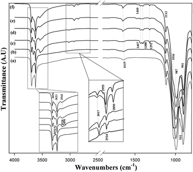 |
| | Fig. 3 FTIR spectra of (a) KR, (b) KB, (c) KD, (d) KM, (e) KC and (f) KS. | |
After intercalation with DMSO, the stretching vibration of the inner hydroxyl groups was not affected; however, one new band appeared at 3654 cm−1, which was assigned to the formation of hydrogen bonds with the inter lamellar hydroxyl groups of the kaolinite (SO–HO).21 Two other observed bands at 3528 cm−1 and 3490 cm−1 result from hydrogen bonding of the DSMO molecules with the inner-surface hydroxyl groups of the kaolinite layers.23 The apparition of new bands corresponds to the vibrations of the methyl groups in the DMSO molecules: asymmetric CH3 stretching (3017 cm−1), symmetric CH3 stretching (2934 cm−1), asymmetric CH3 deformation (1407 cm−1) and symmetric CH3 deformation (1388 cm−1). This reflects the existence of DMSO molecules in the KD specimen. After methanol-grafting, all the bands were weakened; this decrease in intensity of the bands was attributed to the deintercalation of KD and the intercalation of kaolinite with MeOH.11
KM was further used as a precursor to intercalate with TEOS and CTAB. Fig. 3e and f shows the infrared spectra of KS and KC, respectively. The bands characteristic of inter- and intra-lamellar hydroxyl groups showed no obvious changes; however, the band that appeared at 3654 cm−1 and was attributed to the formation of interlamellar hydroxyl groups in the KD and KM samples disappeared, thereby confirming the functionalization of the kaolinite mineral with either TEOS or CTAB. In addition to the increased intensities of the bands at 3017 cm−1 and 2934 cm−1 corresponding to the antisymmetric and symmetric stretching vibrations of methyl groups (CH3) generated by intercalation of KR with the surfactant,6 another band at 2850 cm−1 was assigned to the stretching vibration of methylene groups (CH2).6 However, the typical band for the interlamellar Al–OH group at 931 cm−1 disappeared for KS, which confirms the participation of the aluminol groups in covalent bonds with the OH groups of both TEOS molecules.24 The presence of two additional bands for KC at 2955 cm−1 and 1460 cm−1 arises from the C–N and N–H groups of the organic modifier, respectively, verifying the intercalation of surfactant molecules between the silicates.6
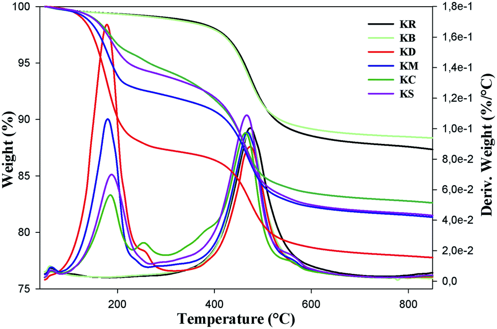
Thermal gravimetric analysis (TGA)
Thermal gravimetric analysis (TGA) was mainly used to compare the effects of the organic molecules in intercalated kaolinite with the pristine and bleached kaolinite. Fig. 4 shows the mass loss (TG) and derivative mass loss (DTG) curves of KR, KB and the intercalation compounds. As shown in the TG curves of the KR and bleached samples, there were two steps, of which the first took place around 56 °C for the raw and bleached kaolinite samples, with mass losses less than 1.2%; this corresponds to the departure of physisorbed water. The second step is related to the dehydroxylation of kaolinite,25 caused by the transformation of kaolinite Al2Si2O5(OH)4 to metakaolinite Al2Si2O7; this generally started at 450 °C and terminated at 600 °C, representing mass losses of 11.44% and 10.4% corresponding to the raw KR and KB samples, respectively. On the other hand, the KD curve presents three major mass losses; the one centered at 178.5 °C corresponds to 13.68% mass loss resulting from the elimination of DMSO molecules,26 and the second one appeared in the same range (450 °C to 600 °C) of the peak of the dehydroxylation of kaolinite, with a decrease in width of the DTG peak.21 There was also a very minor mass loss at about 57 °C, attributed to adsorbed water introduced during the DMSO intercalation.27 The KM sample also displayed a less obvious DTG peak between 60 °C and 200 °C which contributed a mass loss of 8.85%; this was ascribed to the degradation of water, MeOH and methoxy groups between the kaolinite layers.11 Moreover, the last step around 460 °C was probably caused by two simultaneous thermal phenomena: the loss of the grafted methoxy groups and the dehydroxylation of kaolinite.11
 |
| | Fig. 4 Thermogravimetric curves of KR, KB, KD, KM, KC and KS. | |
The TGA patterns of CTAB and TEOS-functionalized kaolinite are mainly characterized by five major mass losses: the first step, associated with the loss of externally adsorbed water, occurred around 56 °C. The second stage, which was due to the decomposition of non-intercalated CTAB and TEOS molecules, occurred around 186 °C; it accounted for 3.85% and 4.96% of the total masses, respectively.28 The third stage, with a total weight loss of 1.58% for CTAB intercalated kaolinite at around 255 °C and a total weight loss of 0.5% for TEOS intercalated kaolinite at around 278 °C, was related to the partial thermal decomposition of organic moieties that were grafted on the external surface of the kaolinite nano-platelets. The decomposition temperature of the TEOS-intercalated kaolinite is higher than the decomposition temperature of the CTAB-intercalated kaolinite, indicating that the hydrogen-bonded molecules (CTAB) are less thermally stable than the covalently bonded molecules (TEOS).29 The weight losses of 10.2% around 474 °C for KC and of 11.52% around 467 °C for KS are associated with the dehydroxylation of the aluminosilicate lattice of kaolinite and the complete decomposition of functionalized molecules grafted onto the SiOH and AlOH groups on the internal surface of kaolinite.30 Finally, weight losses of 1.61 °C for KC and 1.39 °C for KS at around 556 °C were assigned to the evaporation and decomposition of oligomerized molecules and the residual organic and inorganic moieties (CTAB, TEOS). For all kaolinite types, the remaining materials at 800 °C are aluminum oxides and silicon oxides present in the kaolinite structure (Table 2).
Table 2 Data derived from the thermal curves (TGA and DTG) of the intercalated kaolinite compared to pristine kaolinite
| Step |
Characteristics |
Samples |
| KR |
KB |
KD |
KM |
KS |
KC |
| 1 |
Tmax (°C) |
57 |
56 |
57 |
59 |
57 |
56 |
| Mass loss (%) |
1.21 |
1.24 |
0.1 |
0.21 |
0.16 |
0.15 |
| 2 |
Tmax (°C) |
— |
— |
178.52 |
180.1 |
186.4 |
181.08 |
| Mass loss (%) |
|
|
13.68 |
8.85 |
4.96 |
3.85 |
| 3 |
Tmax (°C) |
— |
— |
— |
— |
279.2 |
255.72 |
| Mass loss (%) |
— |
— |
— |
— |
0.5 |
1.58 |
| 4 |
Tmax (°C) |
474.26 |
472.59 |
475.03 |
468.95 |
477.2 |
464.92 |
| Mass loss (%) |
11.44 |
10.4 |
8.46 |
9.77 |
11.52 |
10.2 |
| 5 |
Tmax (°C) |
— |
— |
— |
— |
555.87 |
555.68 |
| Mass loss (%) |
— |
— |
— |
— |
1.39 |
1.61 |
| Residual wt (%) |
87.35 |
88.36 |
77.76 |
81.35 |
81.50 |
82.61 |
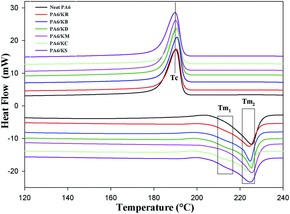
Scanning calorimetry (DSC)
Differential scanning calorimetry (DSC) was used to investigate the impact of the chemical functionalization of the kaolinite nanoparticles on the melting temperature (Tm), crystallization temperature (Tc), specific enthalpy of melting (ΔHm), and the degree of crystallinity (Xc). Fig. 5 presents the DSC curves of the neat PA6 and PA6 nanocomposites with pristine, bleached and intercalated kaolinite; their melting thermograph parameters are summarized in Table 3. It was noted that neat PA6 presents only one endothermic peak at a melting temperature (Tm1) of approximately 225.51 °C, which is ascribed to the melting of α crystals and is characterized by a melting enthalpy (ΔHm) of 56.33 J g−1.31 On the other hand, the incorporation of kaolinite nanoparticles preferentially leads to the appearance of another endothermic peak at around 211 °C, corresponding to γ crystals; this is defined as Tm2.31 These γ crystals always show lower melting temperatures compared to the more stable α crystals.31 This transformation from α to thermodynamic γ structures is generated by the capability of the amide groups along the PA6 polymer chain to form intrachain hydrogen bonds with the OH ions in the basal plane of the kaolinite and become aligned along the crystallographic direction of the a-axis.32 As listed in Table 3, it can be seen that there is a minor change in the Tm2 of the neat PA6 and PA6 nanocomposites with pristine, bleached and intercalated kaolinite; a maximal shift occurs from 225.51 °C for the neat PA6 to 223.42 °C for the PA6/KS nanocomposite. Probably, the kaolinite nanoparticles did not act as a nucleating agent, which generally favors the formation of crystal nuclei. This result can also be evidenced by the temperature of crystallization (Tc) values of around 190 °C of the nanocomposites in relation to the pure PA6 polymer.33 In general, it can be observed that the crystallinity degrees (Xc) of the nanocomposites increased compared to that of the neat PA6 polymer. This can be attributed to the interaction of the kaolinite nanoparticles with the phase of PA6; this restricted the mobility of the polymer chains, hindering the crystallization process. Finally, the melt enthalpy (ΔHm) of the PA6 nanocomposites significantly decreased with the incorporation of kaolinite nanoparticles; this indicates that the thermal stability of the polymer matrix improved with the addition of kaolinite nanoparticles.34
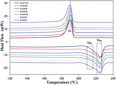 |
| | Fig. 5 DSC curves of the nanocomposite polymer compounds of PA6: neat PA6, KR, KB, KD, KM, KC and KS. | |
Table 3 DSC results for the nanocomposite polymer compounds of PA6
| |
Tm1 (°C) |
Tm2 (°C) |
Tc (°C) |
ΔHm (J g−1) |
Xc (%) |
| PA6 |
— |
225.51 |
190.03 |
56.33 |
29.49 |
| PA6/KR |
210.93 |
224.15 |
190.41 |
55.62 |
31.65 |
| PA6/KB |
210.91 |
224.71 |
190.61 |
53.21 |
30.28 |
| PA6/KD |
211.37 |
225.31 |
190.44 |
55.39 |
31.52 |
| PA6/KM |
211.36 |
225.5 |
190.17 |
55.46 |
31.56 |
| PA6/KS |
210.51 |
223.42 |
190.38 |
54.58 |
31.06 |
| PA6/KC |
211.84 |
224.74 |
189.81 |
54.23 |
30.86 |
Scanning electron microscopy (SEM)
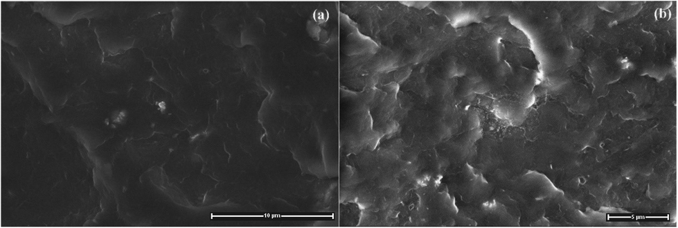
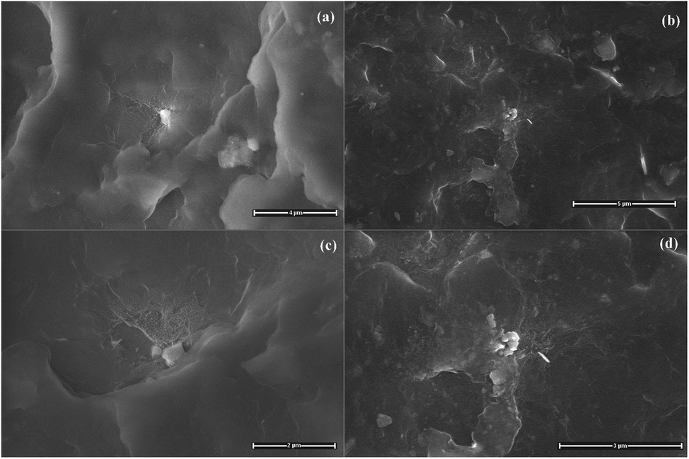
A general view of the micrographs of the kaolinite powder and the composites reinforced by pristine, bleached and functionalized kaolinite can be observed in Fig. 6–8. The stronger particles intermolecular forces, namely cohesive tension can lead the kaolin particles to aggregate and to form the agglomerates. It can be seen from Fig. 6a that the kaolinite mineral possesses pseudo-hexagonal plate-like particles with widely irregular shapes, rough surfaces, and different particle sizes (smaller than 12.5 μm). The SEM images of the PA6 composites reinforced by pristine and bleached kaolinite are presented in Fig. 6b–d, along with the mapping of C, N, O, Si, Al, Fe, Ca elements measured by EDAX. These figures show good dispersion distributions of the kaolinite particles, with some aggregates in both the raw and bleached kaolinite composites. Furthermore, EDAX analysis proved the presence of kaolinite particles on the surfaces based on the elemental analysis data of alumina and silica oxides in major quantities, with traces of other minerals such as iron and calcium minerals that are absent in the case of bleached kaolinite.35 Fig. 7 shows the morphological evolution due to intercalation of bleached kaolinite by DMSO and MeOH molecules. The modification of kaolinite powder by DMSO and MeOH molecules leads to disintegration of the hexagonal structure of kaolinite into smaller particles, resulting in a good distribution of kaolinite particles in the polymer matrix. On the other hand, Fig. 8 presents SEM images of the composites based on KS and KC particles. The micrographs show excellent dispersion–distributions with no agglomeration; indeed, the functionalized kaolinite exhibits average sizes of approximately 601 nm and 700 nm for KS and KC, respectively. These results indicate that exfoliation of kaolinite layers has occurred in the nanocomposites.36
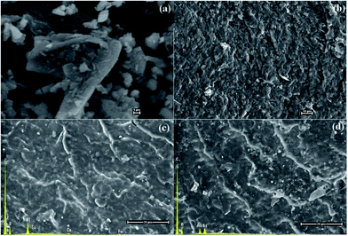 |
| | Fig. 6 SEM photomicrographs of (a) raw kaolinite powder and (b) neat PA6, and SEM-EDAX patterns of the (c) PA6/KR and (d) PA6/KB composites. | |
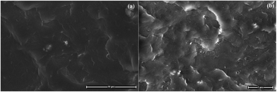 |
| | Fig. 7 SEM photomicrographs of the (a) PA6/KD and (b) PA6/KM composites at ×7500 magnification. | |
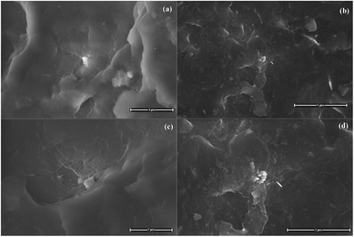 |
| | Fig. 8 SEM photomicrographs of the (a) PA6/KS and (b) PA6/KC composites at ×12500 magnification and the (c) PA6/KS and (d) PA6/KC composites at ×25000 magnification. | |
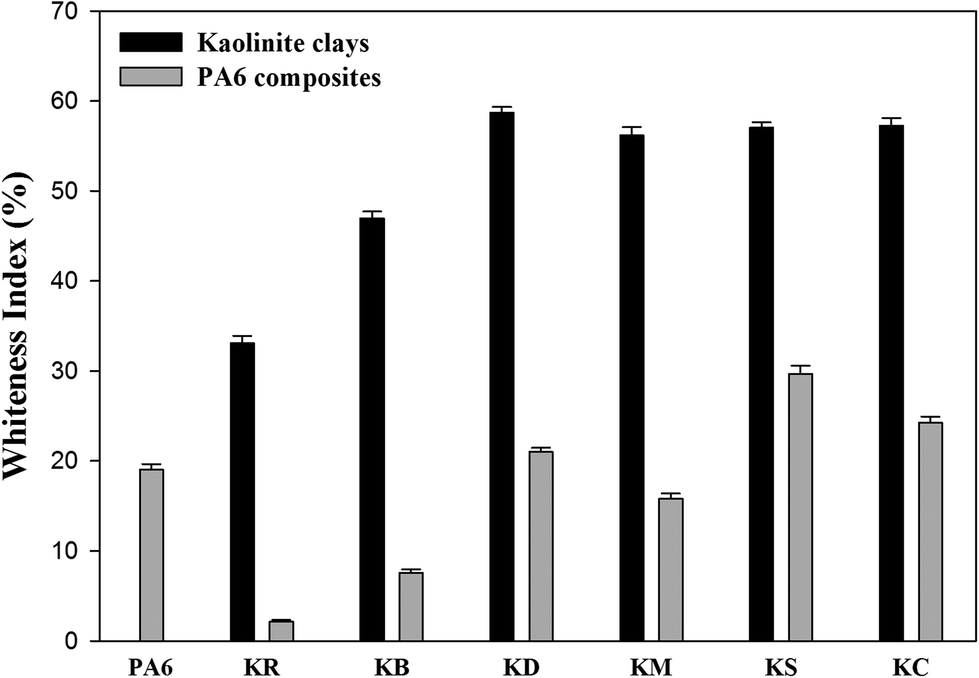
Whiteness indices
In order to study the possibility of bleaching kaolinite powders via chemical processing, the CIE whiteness index values were measured.16 The whiteness indices (WI) of the kaolinite powders and their nanocomposite specimens are shown in Fig. 9. In Fig. 9a, it can be seen that the whiteness index of kaolin was improved firstly through the bleaching treatment and then by the chemical intercalation. Precisely, the use of leaching agent exhibited a significant increase in the whiteness index of kaolinite powder from 33.09%, yielding a value of 46.97%. This confirms that oxalate solution can be employed to dissolve iron oxide compounds as coloring impurities.37 From Fig. 9a, it can be observed that the pre-intercalation of kaolinite by DMSO can increase the whiteness index of kaolinite to a value of 58.70%; this is due to expansion of the interlayer distance of kaolinite, which provides improved brightness and opacity due to the increased specific surface area of the kaolin particles. However, the KM sample shows a slight decrease in the whiteness index value to 56.16%; this is ascribed to the decrease of the basal spacing value of the dried sample, which is generated by the escape of methanol molecules from the interlayer space of kaolinite during the drying process. This is in agreement with previous XRD results.38 In the cases of both intercalated kaolinite samples (KC and KS), the whiteness indices increased to 57.02% and 57.26%, respectively. This increment can be attributed to the higher interlayer distances generated by the great intercalation of molecules in the interlayer spaces of kaolinite.39
 |
| | Fig. 9 Whiteness indices of kaolinite powders and the nanocomposite polymer compounds of PA6–kaolinite after different modification. | |
Fig. 9b shows the whiteness index values of the raw and intercalated kaolinite nanocomposites. The whiteness index of the nanocomposite remarkably decreases upon the incorporation of raw kaolinite in the PA6 polymer matrix, from a value of 19.04% to 2.17%; this can be explained by the opaque white to yellow color of raw kaolinite particles and their refractive properties due to their higher particle sizes. However, as the particle size of kaolinite decreases upon intercalation, the nanocomposites will tend to diffract the incident light and present a higher whiteness index.40 This effect is likely due to a combination of the color of the intercalated kaolinite particles, their greater surface curvature and roughness, and the good dispersion–distribution of the kaolinite particles into the polymer matrix; these effects consequently altered the light-scattering properties, resulting in a whiter appearance.41 In the case of KS, the whiteness index presents the highest value (29.69%) due to the condensation of the silane-coupling agents to hydrophobic/hydrophilic silica particles during the compounding process under high temperature; these silica particles are white in colour.
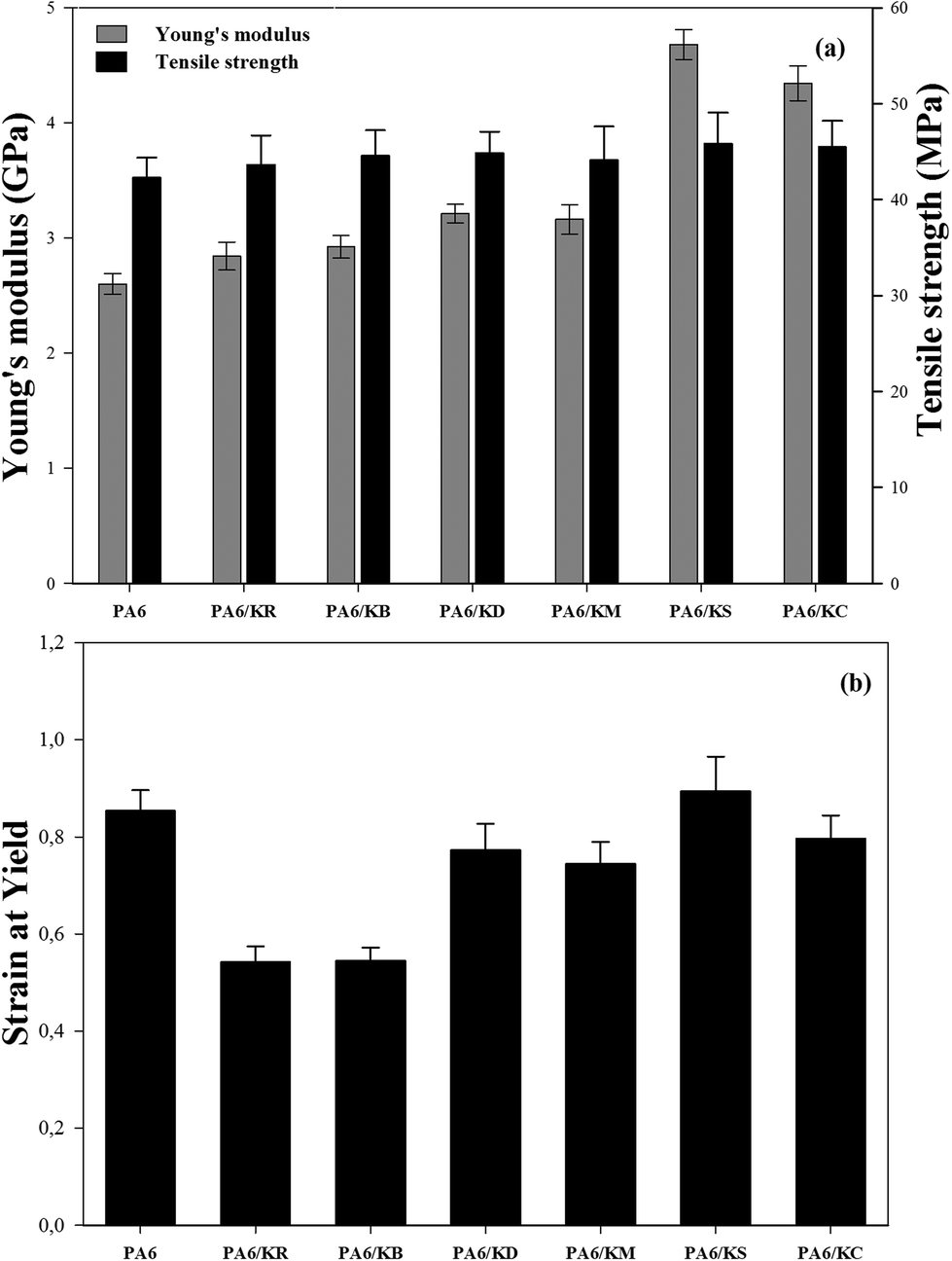
Tensile testing
Fig. 10 shows the effects of the kaolinite nanoparticles and their exfoliation process on the Young's modulus, tensile strength, and strain at yield results of the nanocomposite polymer compounds of PA6–kaolinite. The obtained results (Fig. 10a) show that the Young's modulus values were increased by the incorporation of 8 wt% kaolinite particle content from 2600 MPa for neat PA6 to 2842 MPa and 2924 MPa for raw and bleached kaolinite particles, respectively. The respective increases of 9.7% and 12.8% are attributed to the higher rigidity of the kaolinite particles compared to the matrix.18 On the other hand, the nanocomposites containing kaolinite nanoparticles that were intercalated by DMSO or MeOH molecules showed higher Young's modulus values than those containing unmodified kaolinite particles, representing improvements of 23.9% and 21.9%, respectively. This improvement in the Young's modulus values can be attributed to the large aspect ratio and high intrinsic mechanical characteristics as well as the good dispersion/distribution homogeneity of the kaolinite nano-platelets into the polymer matrix that is generated by the exfoliation of both the DMSO and MeOH intercalated kaolinite samples during the compounding process.42 Likewise, the Young's moduli of the nanocomposite polymer compounds of PA6–kaolinite increase to 4681 MPa and 4342 MPa for 8 wt% addition of KS and KC nanoparticle content, corresponding to percentage growths of 80.6% and 67.5%, respectively. This spectacular enhancement of the Young's modulus cannot be only ascribed to the large aspect ratio and the homogeneous distribution of both KC and KS nanoparticles. It must also be attributed to the strong interfacial interaction between the kaolinite nanoparticles and PA6 chains via forming hydrogen bonds (CTAB)43 or covalent bonds (TEOS)44 between the hydroxyl groups of the kaolinite nano-platelets and the polyamide-6 polymer; this is known to induce better compatibility and high adhesion of kaolinite nanoparticles with the hydrophobic PA6 polymer. Various polyamide 6 composites with different fillers at micro and nanoscale sizes can be found in the literature to compare with our results (see Table 4). These results allow us to conclude that the Young's modulus improvement was observed at a lower content for nano-sized fillers compared to micrometric-sized fillers. Furthermore, the use of just 8 wt% modified kaolinite may lead to a tensile modulus value close to that which is attained by the use of modified montmorillonite as a type of swelling clay.
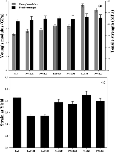 |
| | Fig. 10 Tensile properties of the nanocomposite polymer compounds of PA6–kaolinite: (a) the Young’s modulus and tensile strength, (b) strain at yield. | |
Table 4 Properties of the polyamide 6 composites
| Sample |
E modulus (GPa) |
| PA-6 |
2.6 (ref. 45) |
| PA-6 + 20 wt% glass fiber |
6.5 (ref. 46) |
| PA-6 + carbon nanotube wet-laid composites |
3.5 (ref. 47) |
| PA-6 + 20 wt% cellulose fiber |
4.0 (ref. 48) |
| PA-6 + 20 wt% talc |
6.7 (ref. 46) |
| PA-6 + 3 wt% graphene nanosheets |
4.1 (ref. 49) |
| PA-6 + 5 wt% modified montmorillonite |
5.85 (ref. 50) |
| PA-6 + 5 wt% modified saponite |
3.8 (ref. 50) |
| PA-6 + 8 wt% modified kaolinite (this work) |
4.68 |
Fig. 10a also depicts the tensile strength data for the nanocomposite polymer compounds of PA6–kaolinite. As shown in this figure, slight improvements in the tensile strength values were observed upon the incorporation of 8 wt% kaolinite particle content, from 42.23 MPa for neat PA6 polymer to 43.64 MPa and 44.57 MPa for raw and bleached kaolinite particle loading, respectively. This increment is related to the physical anchoring between the kaolinite particles and the PA6 polymer chains, which lead to transfer of the stress from the matrix to the kaolinite particle interface.51,52 However, in the case of the nanocomposites containing kaolinite nanoparticles that were intercalated by DMSO or MeOH molecules, the tensile strength showed remarkable increases, up to 44.84 MPa and 44.1 MPa for 8 wt% addition of KD and KM nanoparticles, respectively. This enhancement occurs due to the improved size distribution and dispersion of DMSO or MeOH intercalated kaolinite nano-platelets within the PA6 polymer matrix generated by the delamination or exfoliation of kaolinite nanoparticles during the melt compounding nanocomposite preparation process.29 Finally, the use of functionalized nano-platelet kaolinite enables enhancement of the tensile strength properties of the nanocomposite polymer compounds of PA6–kaolinite due to the more efficient load transfer from the PA6 matrix to the kaolinite nano-platelets. By analyzing the results in Fig. 8, it is possible to observe that the values of the tensile strength of the PA6 nanocomposites increased more by the loading of KS (45.85 MPa) and KC (45.47 MPa) nanoparticles. In fact, the exfoliation process can play an important role in the decrease of the size of the kaolinite nanoparticles and improve the filler dispersion/distribution in the polymer matrix. In addition to the enhanced interfacial adhesion and the compatibility between the components, these are the main causes of the high tensile strength properties engendered in our study by the use of surfactant (CTAB) and, more, by the use of silane molecules (TEOS).43
The extracted percentage of the strain at yield for the nanocomposite polymer compounds of PA6–kaolinite are plotted in Fig. 10b. The incorporation of both raw and bleached kaolinite particles in the ductile polymer matrix exhibits a remarkable decrease in the strain at yield values due to the decreased plastic energy in the composites by the addition of rigid kaolinite particles.53,54 Adding the kaolinite particles to the polymer composites achieved less deformability of the materials because of the stress concentration engendered by the presence of decohesion between the kaolinite particles and the polymer matrix, accelerating the composite breakage.55 In the case of the addition of the nanoscale-size kaolinite particles to the produced nanocomposites, the effects of the KD and KM nanoparticles are less pronounced on the strain at yield values because of their high surface areas and their interaction with the polymer matrix, which is more favorable to stress transfer compared to the KR and KB particles. This can enable the conclusion that exfoliation of kaolinite particles in the ductile matrix can mask the stiffness of the kaolinite particles and lead to a large aspect ratio of the nanoparticles.29 It can also be observed in Fig. 10b that the strain at yield values of the nanocomposites reinforced by KS or KC nanoparticles may have improved because the functionalization of the nanoparticles enhances the interaction between the hydroxyl groups of the kaolinite nano-platelets and the polyamide-6 chains via hydrogen bonding or covalent bonding, which impedes good stress transfer.
Conclusions
Oulmes kaolin rock contains kaolinite as the major mineral, with small quantities of muscovite and illite as well as iron oxides as the major impurities. These latter minerals are mainly present in the coarser fractions and are removed during the purification and bleaching process. In this work, iron dissolution from kaolin mineral occurred via a leaching reaction in aqueous oxalic acid as a solvothermal agent with consequently excellent whitening results of the kaolinite, as proved by the high whiteness index. The use of the displacement method to intercalate the kaolinite particles was examined by various physicochemical techniques, including FTIR spectroscopy, XRD, and TGA. The results suggest the formation of new chemical bonds between the hydroxyl groups of the kaolinite nanoparticles and the chemical groups of the used intercalated molecules. The great exfoliation and decrease of the kaolinite nanoparticle size were confirmed by the high optical clarity of the nanocomposites and their SEM micrographs. Finally, the addition of pristine and intercalated kaolinite was shown to increase the thermal stability and mechanical properties; however, the functionalization of kaolinite nanoparticles improved both behaviours due to the greet interfacial adhesion, high aspect ratio and random dispersion/distribution of kaolinite nano-particles in the polymer matrix.
Conflicts of interest
There are no conflicts to declare.
Acknowledgements
The authors would like to thank the MAScIR foundation for the financial support of this work.
Notes and references
- B. Guo, Q. Zou, Y. Lei and D. Jia, Polym. J., 2009, 41, 835–842 CrossRef CAS.
- K. El Bourakadi, N. Merghoub, M. Fardioui, M. E. M. Mekhzoum, I. M. Kadmiri, E. M. Essassi, A. e. K. Qaiss and R. Bouhfid, Composites, Part B, 2019, 172, 103–110 CrossRef CAS.
- V. Gupta, S. Rajagopal and N. Gupta, Int. J. Damage Mech., 2011, 236 Search PubMed.
- C. H. Sampaio, J. Solid State Chem., 2018, 260, 106–116 CrossRef.
- M. Alkan, Ç. Hopa, Z. Yilmaz and H. Güler, Microporous Mesoporous Mater., 2005, 86, 176–184 CrossRef CAS.
- M. A. Zenasni, B. Meroufel, A. Merlin and B. George, J. Surf. Eng. Mater. Adv. Technol., 2014, 4, 332–341 CAS.
- R. A. H. Hernández, F. L. García, L. E. H. Cruz and A. B. Jacuinde, J. Mex. Chem. Soc., 2015, 59, 198–202 Search PubMed.
- R. A. Hernández-Hernández, F. Legorreta-García, L. E. Hernández-Cruz, E. A. Chavez-Urbiola and E. Salinas-Rodríguez, Minerals, 2016, 6, 60 CrossRef.
- N. Zari, M. Raji, H. El Mghari and R. Bouhfid, in Polymer-based Nanocomposites for Energy and Environmental Applications, Woodhead, 2018, pp. 75–103 Search PubMed.
- U. K. Sultana, F. Gulshan and A. S. W. Kurny, Mater. Sci. Metall. Eng., 2014, 2, 5–10 CAS.
- X. Zuo, D. Wang, S. Zhang, Q. Liu and H. Yang, Minerals, 2018, 8, 112 CrossRef.
- D. Wang, Q. Liu, D. Hou, S. Zhang, P. Guo and H. Cheng, J. Braz. Chem. Soc., 2018, 29, 33–37 CAS.
- S. Wang, X. Zuo, H. Cheng, Y. Yanga and Q. Liu, J. Braz. Chem. Soc., 2016, 27, 1311–1318 CAS.
- M. Raji, H. Essabir, E. M. Essassi, D. Rodrigue, R. Bouhfid and A. e. K. Qaiss, Polym. Polym. Compos., 2016, 16, 101–113 Search PubMed.
- ASTM International, D 4703-03, Standard Practice for Compression Molding Thermoplastic Materials into Test Specimens, Plaques, or Sheets Search PubMed.
- ASTM International, E313-15e1, Standard Practice for Calculating Yellowness and Whiteness Indices from Instrumentally Measured Color Coordinates Search PubMed.
- ISO 527-1:2012, Plastics-Determination of Tensile Properties-Part 1: General Principles Search PubMed.
- A. Zegeye, S. Yahaya, C. I. Fialips, M. L. White, N. D. Gray and D. A. C. Manning, Appl. Clay Sci., 2013, 86, 47–53 CrossRef CAS.
- R. B. Scorzelli, L. C. Bertolino, A. B. Luz, M. Duttine, F. A. N. G. Silva and P. Munayco, Clay Miner., 2008, 43, 129–135 CrossRef CAS.
- Y. Kuroda, K. Ito, K. Itabashi and K. Kuroda, Langmuir, 2011, 27, 2028–2035 CrossRef CAS PubMed.
- S. Q. Yang, P. Yuan, H. P. He, Z. H. Qin, Q. Zhou, J. X. Zhu and D. Liu, Appl. Clay Sci., 2012, 62–63, 8–14 CrossRef CAS.
- K. R. H. M. Jawaid, A. e. K. Qaiss and R. Bouhfid, Nanoclay Reinforced Polymer Composites, 2016 Search PubMed.
- H. Cheng, X. Hou, Q. Liu, X. Li and R. L. Frost, Appl. Clay Sci., 2015, 109–110, 55–63 CrossRef CAS.
- H. He, Q. Tao, J. Zhu, P. Yuan, W. Shen and S. Yang, Appl. Clay Sci., 2013, 71, 15–20 CrossRef CAS.
- N. J. Saikia, D. J. Bharali, P. Sengupta, D. Bordoloi, R. L. Goswamee, P. C. Saikia and P. C. Borthakur, Appl. Clay Sci., 2003, 24, 93–103 CrossRef CAS.
- E. H. de Faria, O. J. Lima, K. J. Ciuffi, E. J. Nassar, M. a Vicente, R. Trujillano, P. S. Calefi, E. H. De Faria, O. J. Lima, K. J. Ciuffi, E. J. Nassar, M. A. Vicente, R. Trujillano, P. S. Calefi and E. H. de Faria, J. Colloid Interface Sci., 2009, 335, 210–215 CrossRef CAS.
- S. Letaief and C. Detellier, Mater. Chem., 2007, 48, 1476–1484 RSC.
- J. Matusik and K. Zenon, Appl. Clay Sci., 2013, 83–84, 433–440 CrossRef CAS.
- M. Raji, M. E. M. Mohamed Mekhzoum, D. Rodrigue, A. E. K. Qaiss and R. Bouhfid, Composites, Part B, 2018, 146, 106–115 CrossRef CAS.
- E. H. de Faria, K. J. Ciuffi, E. J. Nassar, M. A. Vicente, R. Trujillano and P. S. Calefi, Appl. Clay Sci., 2010, 48, 516–521 CrossRef CAS.
- S. Gomari, I. Ghasemi, M. Karrabi and H. Azizi, Polyolefins J., 2015, 2, 99–108 Search PubMed.
- U. Klun and A. Krz, Polym. Adv. Technol., 2003, 822, 817–822 Search PubMed.
- T. X. Liu, Z. H. Liu, K. X. Ma, L. Shen, K. Y. Zeng and C. B. He, Compos. Sci. Technol., 2003, 63, 331–337 CrossRef CAS.
- H. Bensalah, K. Gueraoui, H. Essabir, D. Rodrigue, R. Bouhfid and A. E. K. Qaiss, J. Compos. Mater., 2017, 1–14 Search PubMed.
- M. Eid and A. Elsayed, Journal of American Science, 2014, 9, 523–533 Search PubMed.
- S. Letaief, J. Leclercq, Y. Liu and C. Detellier, Langmuir, 2011, 27, 15248–15254 CrossRef CAS.
- R. A. H. Hernández, F. L. García, L. E. H. Cruz and A. M. Luévanos, IOP Conf. Ser.: Mater. Sci. Eng., 2013, 45, 012002 Search PubMed.
- H. Cheng, Q. Liu, X. Cui, Q. Zhang, Z. Zhang and R. L. Frost, J. Colloid Interface Sci., 2012, 376, 47–56 CrossRef CAS.
- D. A. Refaei, M. K. Abdelrahman, I. A. Ibrahim, F. Eldears and A. T. Kandil, Int. J. Adv. Technol., 2017, 8, 1–6 Search PubMed.
- C. DeArmitt and M. Hancock, in Particulate-Filled Polymer Composites, pp. 357–424 Search PubMed.
- A. J. Gravelle, S. Barbut and A. G. Marangoni, RSC Adv., 2015, 5, 60723–60735 RSC.
- V. V. Raji, S. Ramakrishnan, R. Sukumar, M. Brahmakumar and A. R. Menon, Polym. Int., 2015, 64, 1585–1593 CrossRef CAS.
- W. H. Hoidy and E. A. J. Al-mulla, Iraqi Natl. J. Chem., 2013, 49, 61–72 Search PubMed.
- M. Beauvais, L. Serreau, C. Heitz and E. Barthel, J. Colloid Interface
Sci., 2009, 331, 178–184 CrossRef CAS PubMed.
- E. O. Ogunsona, M. Misra and A. K. Mohanty, RSC Adv., 2017, 7, 8727–8739 RSC.
- F. C. Fernandes, R. Gadioli, E. Yassitepe and M. De Paoli, Polym. Compos., 2016, 37, 915–924 CrossRef.
- T. Okazaki, Carbon Nanotub. Graphene, 2nd edn, 2014, vol. 6, pp. 225–252 Search PubMed.
- F. C. Fernandes and M. De Paoli, Soc. Plast. Eng., 2016, 6–9 Search PubMed.
- N. Yesildag, C. Hopmann, M. Adamy and C. Windeck, AIP Conf. Proc., 2017, 1914, 150001 CrossRef.
- B. Gupta, M. F. Lacrampe and P. Krawczak, Polym. Polym. Compos., 2006, 14, 13–38 CAS.
- H. Essabir, M. O. Bensalah, D. Rodrigue, R. Bouhfid and A. Qaiss, Mech. Mater., 2016, 93, 134–144 CrossRef.
- H. Essabir, M. Raji and R. Bouh, in Nanoclay Reinforced Polymer Composites, 2016, pp. 29–49 Search PubMed.
- M. Raji, H. Essabir, R. Bouhfid and A. el kacem Qaiss, in Handbook of Composites from Renewable Materials, John Wiley & Sons, Inc., Hoboken, NJ, USA, 2017, pp. 225–252 Search PubMed.
- H. Essabir, M. Raji, E. M. Essassi, D. Rodrigue, R. Bouhfid and A. el kacem Qaiss, J. Mater. Sci.: Mater. Electron., 2017, 28, 17120–17130 CrossRef CAS.
- M. Raji, H. Essabir, D. Rodrigue, R. Bouhfid and A. Qaiss, Polym. Compos., 2017, 39, 2932–2941 CrossRef.
|
| This journal is © The Royal Society of Chemistry 2020 |
Click here to see how this site uses Cookies. View our privacy policy here. 
 Open Access Article
 This Open Access Article is licensed under a Creative Commons Attribution-Non Commercial 3.0 Unported Licence
 ,
Abou el kacem Qaiss
,
Abou el kacem Qaiss