
 Open Access Article
 This Open Access Article is licensed under a Creative Commons Attribution-Non Commercial 3.0 Unported Licence
One-step controllable synthesis of three-dimensional WO3 hierarchical architectures with different morphologies decorated with silver nanoparticles: enhancing the photocatalytic activity†
R. A. Capelia,
C. J. Dalmaschio b,
S. R. Teixeirac,
V. R. Mastelarod,
A. J. Chiquitoe,
E. Longof and
F. M. Pontes*a
b,
S. R. Teixeirac,
V. R. Mastelarod,
A. J. Chiquitoe,
E. Longof and
F. M. Pontes*a
aDepartment of Chemistry, Universidade Estadual Paulista – Unesp, P. O. Box 473, 17033-360, Bauru, São Paulo, Brazil. E-mail: fenelon@fc.unesp.br; Fax: +55 14 3103 6088; Tel: +55 14 3103 6135
bDepartment of Chemistry, Universidade Federal do Espírito Santo – UFES, 29075-910, Vitória, Espírito Santo, Brazil
cDepartament of Physics, Faculdade de Ciências e Tecnologia – FCT, Universidade Estadual Paulista, Rua Roberto Simonsen, 305, 19060-900 – Presidente Prudente, SP, Brazil
dPhysics Institute of São Carlos (IFSC), University of São Paulo, São Carlos, SP, Brazil
eNanO LaB – Department of Physics, Universidade Federal de São Carlos, Via Washington Luiz, km 235, P. O. Box 676, São Carlos, 13565-905, São Paulo, Brazil
fLIEC – CDMF – Department of Chemistry, Universidade Federal de São Carlos, Via Washington Luiz, km 235, P. O. Box 676, São Carlos, 13565-905, São Paulo, Brazil
First published on 13th February 2020
Abstract
Hierarchical architecture self-assembled three-dimensional WO3 and WO3·Ag with high uniformity have been successfully obtained using peroxopolytungstic acid as precursor and silver in a morphological engineering approach under moderate hydrothermal conditions. The as-grown samples were characterized by XRD, FEG-SEM, HRTEM, TGA, Raman, FTIR, UV-Vis, and XPS. In addition, the photocatalytic performance of the hierarchical architecture self-assembled three-dimensional WO3 and WO3·Ag has also been investigated through degradation of Rhodamine B (RhB) dye under 467 nm LED light irradiation. Results show that the hierarchical architecture self-assembled three-dimensional shapes evolve (depending on the silver amount) from 3D irregular-platelet-like building blocks to 3D hexagonal building blocks then to three-dimensional hexagonal-football-like and finally to 3D multi-branched spiky ball-like microcrystals. Also, high-magnification FEG-SEM and HRTEM images showed that the Ag nanoparticles with diameter about 5–15 nm were anchored on the surface of the 3D hierarchical architecture. UV-Vis measurements demonstrated that the 3D hierarchical structures gradually absorbed more light when the Ag content was increased. Moreover, the band-gap energy to WO3·0.20Ag was from Eg = 2.48 eV. It was found that 3D multi-branched spiky ball-like WO3·0.20Ag (corresponding to 1.2748 g of the AgNO3) microcrystals show outstanding photocatalytic activity in the photodegradation of RhB dye compared with other 3D hierarchical architectures.
1. Introduction
In the last few decades, the hierarchical architecture crystal-growth technology (HACGT) has received tremendous attention in the development of the next-generation of hybrid nanostructures. Among many options, oxide-based semiconductors are useful building blocks for the hierarchical architecture growth.1–5 Although many studies on the development of hierarchical architecture using oxide-based semiconductors have been conducted, it remains a challenge to develop a facile and cost-effective procedure for producing such materials with practical applications. However, it has been demonstrated that these single oxide-based semiconductors exhibit a significant limitation in achieving practical applications.These limitations are overcome, for instance, by engineered heterojunctions formed by two oxide-based semiconductors or decoration (anchoring) of noble metal nanoparticles on the surface of oxide-based semiconductor hierarchical structures which display a tremendous improvement in their properties (e.g. physical, chemical, physicochemical, biological, mechanical, etc.) in comparison to single oxide-based semiconductor hierarchical architectures. Particularly, growing noble-metal nanoparticles (e.g., Ag, Au, Pt, Cu, and Pd) directly on the surface of these hierarchical crystals (e.g., ZnO, MoO3, TiO2, ZrO2, SiO2, WO3, CeO2, CuO, SnO, etc.), is an effective and suitable way to control size, shape, crystalline structure and composition of the hierarchical crystals.6–10
These hybrid hierarchical architecture materials offer a wide range of technological applications including development of smart materials or intelligent systems; development of materials for application in nanobiotechnology, optoelectronics, sensors, solar cells, and photocatalysis.11–14 In addition, the presence of the noble metal nanoparticles can influence the morphology and properties of materials.14,15 It has been shown that the presence of the noble metal nanoparticles can effectively tune the Fermi level of hierarchical architecture as well as enhances (photoexcited electrons/hole pairs) charges separation efficiency, resulting in gas-sensing response and photocatalytic activity enhancement. Additionally, hybrid hierarchical architecture compounds have received much attention in the worldwide environmental pollution issues.14–16
Numerous studies have been published on the synthesis to building hybrid hierarchical architecture materials (nanospheres, nanoflowers, nanowires and other more complex structures), such as hydrothermal, solvothermal, sol–gel, chemical precipitation, photodeposition, physical vapor deposition, microwave-assisted chemical route, template-based technique, and inkjet printing.7,17–21
Recently, Xu et al.6 have reported 3D tree-like hierarchical TiO2 nanotube arrays decorated with Ag nanoparticles prepared by one-step hydrothermal route. The photocatalytic activity for the degradation of Rhodamine B was significantly improved under UV-Visible light irradiation in comparison with pure TiO2. Vinh Do et al.22 have investigated TiO2 hierarchical nanostructures decorated with Au nanoparticles, which improved the photocatalytic performance.
Based on above considerations, three-dimensional hierarchical WO3 structures with complex morphologies and unique properties have attracted considerable attention.23–27 Therefore, the effectiveness of WO3 in various applications highly depends on control over their size, shape, composition, and crystal phase, all of which are directly influenced by either the synthesis process, doping or decoration of the surface with noble metal nanoparticles. In addition, the morphology is a key factor influencing the properties of WO3 as different shapes contain a different number of sites for reaction.
Consequently, 3D hybrid hierarchical architecture engineering of WO3 have drawn intensive attention in the field of sensing and environmental remediation. For instance, Xiang et al.28 have reported WO3 nanorods decorated with Au nanoparticles; the photocatalytic activity for the degradation of Rhodamine B dye was greatly improved. Acharyya et al.29 have used cationic surfactant CTAB (cetyl trimethylammonium bromide) to synthesize 3D hierarchical silver supported WO3 flower-like microspheres, and showed promising performance in pollutant degradation. Ding and co-workers30 have reported selective deposition of Ag nanoparticles onto hexagonal WO3 nanorods fabricated by a hybrid process involving hydrothermal treatment followed by in situ photo-reduction. Xiang and co-workers31 have reported successful growth of Au nanoparticles anchored on the monoclinic surface of WO3 nanorods after annealing at 500 °C for 2 h. Xiaoyu et al.32 have reported three-dimensional Ag2O/WO3·0.33H2O hierarchical structures fabricated by chemical precipitation method for improving photocatlytic activity. Ren and co-workers8 have reported the synthesis of Ag nanoparticles anchored on urchin-like WO3·0.33H2O hierarchical structure. The as-prepared hybrid hierarchical structure showed better photodegradation of Rhodamine B dye in comparison single WO3·0.33H2O.
Although many studies on the development of 3D hierarchical structure using WO3 have been conducted, it remains a challenge to develop a facile and cost-effective procedure for producing such materials without using surfactant and toxic reagents to design 3D hierarchical hybrid WO3.
Here we report a simple, one-step, additives-free (e.g., citrate ions, surfactant, amines, hydrazine, polymers, etc.) to synthesize of a series of three-dimensional (3D) WO3 hierarchical architecture decorated with Ag nanoparticles targeted at sustainable environmental applications. In order to show the reliability of the method and the ready control of the properties of the synthesized samples, all as-prepared samples were systematically characterized in detail using different and complementary techniques.
2. Experimental procedure
Three-dimensional WO3 hierarchical architecture decorated with Ag nanoparticles with different morphologies were prepared by hydrothermal method due simplicity and low cost sustainable green chemistry approach. All chemicals used in this work, such as tungstic acid (H2WO4), hydrogen peroxide (H2O2, 30%), and silver nitrate (AgNO3), were analytical-grade reagents.First, a yellow solution was prepared by adding 0.375 g of H2WO4 to 10 mL of H2O2 and 30 mL of distilled water. The initially yellow solution discolored after it was mixed for 24 h with a magnetic stirrer, and a colorless solution of peroxopolytungstic acid complex was formed. Next, 0.0637 g (equivalent to 0.01 M Ag), 0.3187 g (equivalent to 0.05 M Ag), and 1.2748 g (equivalent to 0.20 M Ag) of an inorganic salt, AgNO3, were dissolved in the colorless solution. The solution of complex peroxopolytungstic acid and Ag precursor salt was then transferred to a 100 mL Teflon reaction vessel, and the rest of the vessel was filled with distilled water. Finally, the reaction vessel was placed in a stainless steel autoclave, sealed and heated at temperatures 200 °C for 2 h. After finishing the reaction, the reactor was naturally cooled to room temperature, and the turbid suspension was centrifuged to collect the powder, which was washed thoroughly with deionized water several times to remove any unreacted precursors. Finally, the powder was dried in an oven at 70 °C for 24 h. Ag NPs were growth in situ on the three-dimensional WO3 hierarchical architecture during the hydrothermal process. For simplicity, the powders derived from hydrothermal treatment of WO3 (0 M Ag), WO3 (0.01 M Ag), WO3 (0.05 M Ag), and WO3 (0.20 M Ag) are hereafter referred to as W-0.0Ag, W-0.01Ag, W-0.05Ag, and W-0.20Ag, respectively.
The crystal structures were investigated by analyzing XRD patterns of Cu Kα radiation recorded by a diffractometer (Miniflex 600, Rigaku) in 2θ increments of 0.04°. The morphology of the samples was analyzed with a FEG-SEM (Inspect F50, FEI) operated at an accelerating voltage of 5 kV. In addition, EDX spectroscopy was used in connection with FEG-SEM for the elemental analysis. Transmission electron microcopy (TEM/HRTEM) images were obtained with a FEI Tecnai G2 F20 microscope operating at 200 kV. Raman spectra were recorded at room temperature using a spectrometer (Horiba) equipped with a Peltier-cooler charge-coupled device (model HR 550). The samples were excited by a laser with wavelength of 532 nm. FTIR spectra were recorded in the 400–4000 cm−1 range using KBr pellets and an infrared spectrometer (FT/IR-4600, JASCO) with resolution of 4 cm−1 in the transmittance mode.
Thermal characterization was performed by thermogravimetry (TG) using a TG analyzer (SDT-Q600, TA Instruments). The analysis were carried out from room temperature to 1000 °C, at a heating rate of 10 °C min−1, under an air flow of 100 mL min−1, and using alumina crucibles. UV-Vis spectra of the samples were obtained by a UV-Vis spectrophotometer (Lambda 1050, PerkinElmer) equipped with an integrating sphere; MgO was used as the background reference material. XPS was conducted to study the elemental compositions and chemical states of the samples. The XPS spectra were obtained with a spectrometer system (ESCA+, Scienta-Omicron) equipped with a hemispherical analyzer (EA125) and a monochromated Al Kα (Xm1000, 1486.7 eV) radiation source. In order to compensate for the charge effect in the sample, a charge neutralizer (CN10, Omicron) with beam energy of 1.6 eV was used. During the analysis, the chamber was evacuated to 2 × 10⁻⁹ Pa, and the energy steps were 50 and 20 eV for the survey and high-resolution spectra, respectively. The peak fitting was performed using a 70% Gaussian curve, a 30% Lorentzian curve, and a Tougaard nonlinear sigmoid baseline. The C 1s peak of adventitious carbon was fixed at 284.8 eV to set the scale of the binding energy, and the data fitting was performed using CasaXPS software (Casa Software Ltd, UK). The specific surface area was estimated by Brunauer–Emmett–Teller (BET) nitrogen adsorption–desorption method using a Micrometrics ASAP 2010 instrument.
The photocatalytic performance with different Ag-decorated 3D WO3 hierarchical architecture was evaluated by monitoring the photodegradation of Rhodamine B dye from the aqueous solution (denoted as RhB) under LED lamp (467 nm with a light intensity of 40 mW cm−2) as a light source at 23 °C. The photochemical reactor was made of a Pyrex glass jacketed quartz tube (photoreactor vessel, 30 mL). The photocatalytic reaction was performed as follow: 20 mg of photocatalyst to 20 mL of RhB aqueous solution (10 ppm). Prior to irradiation, the suspension was ultrasonicated for 10 min and then magnetically stirred in the dark for 20 min to obtain adsorption equilibrium with photocatalyst. Finally, the solution was then exposed to LED lamp irradiation, 467 nm predominant wavelength. At certain time intervals of irradiation, 1–2 mL aliquots of reaction solution were withdrawn from the photoreactor vessel and centrifuged to remove the catalyst. The supernatant solution was then loaded in a quartz cell with a 10 mm optical path to measure the concentration variation of RhB by recording the corresponding absorbance peak at 554 nm. The optical absorption spectra were recorded on a HP8453 UV-Vis spectrophotometer at room temperature.
3. Results and discussion
X-ray diffraction patterns (XRD) were analyzed to investigate the crystalline quality and phase transformation of the as-prepared samples derived from hydrothermal treatment of WO3 at 200 °C for 2 h in the presence of different silver concentrations. XRD pattern of the as-prepared samples (W-0.0Ag, W-0.01Ag, W-0.05Ag, and W-0.20Ag) shows well-defined peaks correspond crystalline material, Fig. 1. All diffraction peaks in the XRD patterns of as-prepared samples W-0.0Ag can be well indexed to the orthorhombic-WO3·0.33H2O crystal phase with lattice parameters of a = 7.342 Å, b = 12.552 Å, and c = 7.695 Å (JCPDS card no. 72-0199). However, for W-0.01Ag, W-0.05Ag, and W-0.20Ag samples the XRD patterns show that the hexagonal-WO3 crystal phase with lattice parameters of a = 7.2980 Å, b = 7.3980 Å, and c = 3.8990 Å (JCPDS card no. 33-1387). These changes in the crystal structure indicate that the amount of Ag played an important role in the phase transformation, degree of hydration, and stabilization of the crystal structure type. Therefore, it can be concluded that different phases of WO3·nH2O were controlled as the amount of Ag in the hydrothermal growth solution was increased. Balazsi and Pfeifer33 also have demonstrated that the hydration degree on tungsten oxide is very sensitive to the amount of sodium ions during hydrothermal treatment. This observation is also supported by different works, which suggested that the hydration degree, morphology, and crystal structure of tungsten oxide are very sensitive to the concentration of precursor ions solutions, such as HCl, NH4Cl, NH4NO3, (NH4)2SO4, Li2SO4, and Na2SO4.34–37 | ||
| Fig. 1 XRD patterns of pure WO3 and WO3–Ag with different molar amounts of Ag after hydrothermal treatment at 200 °C for 2 h: (a) W-0.0Ag; (b) W-0.01Ag; (c) W-0.05Ag; (d) W-0.20Ag. Standard patterns of orthorhombic WO3·0.33H2O (red solid line) and hexagonal WO3 (blue solid line). | ||
In this work one possible mechanism was presented to explain the phase transformation from orthorhombic-WO3·0.33H2O to hexagonal-WO3. The silver ions acting as a structure-directing agent altered the nucleation and growth mechanisms of WO3 crystals building blocks, resulting in the formation of interstructural hydrogen bonds between layers of WO3 during the hydrothermal route. In the absence of Ag, the peroxopolytungstic acid precursor solution under hydrothermal conditions the precursor will decompose in hydrated tungsten oxide (WO3·0.33H2O) (eqn (1) and 2).
| 12H2WO4 + 8H2O2 → W12O40−8 + 8H3O+ + 16H2O | (1) |
| W12O40−8 + 8H3O+ → 12WO3·0.33H2O + 8H2O | (2) |
When the inorganic salt was added to the hydrothermal growth solution, the ions as Ag+ ions changed the growth environment of the building blocks in the peroxopolytungstic acid precursor solution. Under peroxide solution different peroxopolytungstic species can be generated in pH values. Under acid conditions the specie presented in eqn (3) can be formed. This species under hydrothermal conditions can be decomposed in W2O5 as proposed in eqn (4). Tungsten(V) oxide is suitable to be oxidized (eqn (5)), with favorable electrical potential when combined with silver in acid solution, which will reduced ions to metallic silver nanoparticles (eqn (6)). The equations combined results in a reaction presented in eqn (7).
| 4W(O2)42− + 8H3O+ → 2H2W2O11·H2O + 8H2O2 | (3) |
| 2H2W2O11·H2O → 2W2O5 + 4H2O + 5O2 | (4) |
| 2W2O5 + 4H2O → 4WO3 + 4H3O+ + 4e− | (5) |
| 4Ag+ + 4e− → 4Ag | (6) |
| 4W(O2)42− + 2H2O + 4H3O+ + 4Ag+ → 4WO3 + 4Ag + 8H2O2 + 5O2 | (7) |
When the concentration of Ag+ ions in the hydrothermal growth solution was increased, it promotes a pathway to decomposition of peroxopolytungstic in new building blocks, bond breaking and formation of new bonds are expected. This dynamical process led to a new and stable structure.
Raman spectroscopy was also performed for distinguishing the different phases of tungsten oxide, since this technique is sensitive to the crystal quality, structural defects and disorder degree. As depicted in Fig. 2, the Raman spectra agree very well with the general characteristics of orthorhombic-WO3·0.33H2O crystal phase for W-0.0Ag as-prepared sample (Fig. 2a).38,39 This is in agreement to our results obtained by the XRD. Additionally, the small intensity bands at 946 and 921 cm−1 correspond to stretching vibrations of terminal W![[double bond, length as m-dash]](https://www.rsc.org/images/entities/char_e001.gif) O and W–O bonds, respectively.40 The bands located at 802 and 685 cm−1 can be attributed to stretching vibrations of O–W–O, while the weak shoulder at 629 cm−1 can be attributed to the vibration of bridging oxygen atoms.41 The weak peak at 475 cm−1 may be associated with the vibration of water molecules. The Raman modes located around 337 and 266 cm−1 could have been originated from the bending vibrations of W–O–W.42 In addition, the bands located around 195, 166, and 76 cm−1 are attributed to the lattice vibrations.43
O and W–O bonds, respectively.40 The bands located at 802 and 685 cm−1 can be attributed to stretching vibrations of O–W–O, while the weak shoulder at 629 cm−1 can be attributed to the vibration of bridging oxygen atoms.41 The weak peak at 475 cm−1 may be associated with the vibration of water molecules. The Raman modes located around 337 and 266 cm−1 could have been originated from the bending vibrations of W–O–W.42 In addition, the bands located around 195, 166, and 76 cm−1 are attributed to the lattice vibrations.43
 | ||
| Fig. 2 Raman spectra of pure WO3 and WO3–Ag with different molar amounts of Ag after hydrothermal treatment at 200 °C for 2 h: (a) W-0.0Ag; (b) W-0.01Ag; (c) W-0.05Ag; (d) W-0.20Ag. | ||
The as-prepared samples W-0.01Ag, W-0.05Ag and W-0.20Ag exhibited distinct spectral bands that showed drastically intensity changes, suggesting a local structural change. Upon comparison of the stretching, bending and lattice vibrational modes of as-prepared samples W-0.0Ag, W-0.01Ag, W-0.05Ag, and W-0.20Ag, the Raman modes were found to shift towards higher and lower values, as well as disappear as a function of the increasing Ag contents. For example, the intense vibrational mode located at 72 cm−1 for the orthorhombic-WO3·0.33H2O crystal phase was shifted to 37 cm−1 in the spectrum of sample W-0.01Ag and completely disappeared in the spectrum of samples W-0.05Ag and W-0.20Ag. Interestingly, increase of the Ag contents generated changes in the region characterized by stretching vibrations of terminal WO and W–O bonds at 946 and 921 cm−1, respectively. The bands located at 946 and 921 cm−1 corresponding to the orthorhombic-WO3·0.33H2O phase overlap, and only one band appears at 928, 916 and 910 cm−1 in the spectra of samples W-0.01, W-0.05Ag and W-0.20Ag, respectively. These changes in bands positions are characteristic features of the hexagonal-WO3 crystal phase (Fig. 2b–d). Therefore, both Raman and XRD results confirm the phase transformation from orthorhombic-WO3·0.33H2O to hexagonal-WO3 crystal structure with increasing Ag contents.
In addition, to understand the phase transition process and functional groups present, the as-prepared samples were examined by FTIR technique and the results are depicted in Fig. 3. It has been reported that the orthorhombic-WO3·0.33H2O crystal structure consists of layered stacks of WO5(OH2) octahedra and interlayer water molecules.44–46 For orthorhombic-WO3·0.33H2O, the interlayer water molecules connected the WO5(OH2) octahedra planes through hydrogen bonds. The FTIR spectrum of sample W-0.0Ag shows vibrational bands located at 3494 and 3470 cm−1 (region-4) which are usually attributed to –OH and H2O stretching vibrations, while an additional sharp band due to structural water molecules appears at 1606 cm−1 (region-3) (Fig. 3a). The bands located at 994 and 954 cm−1 (region-2) are assigned to the stretching mode of the terminal WO bond, which is very common for the orthorhombic-WO3·0.33H2O crystal phase. Furthermore, a very strong and broad band between 813 and 730 cm−1 (region-1) and a shoulder at 665 cm−1 (region-1) can be ascribed to O–W–O stretching vibrations. All the bands observed in sample W-0.0Ag can be attributed exclusively to the orthorhombic WO3·0.33H2O phase, which are in good agreement with the work by Daniel et al.43 As previously reported in literature, the crystalline orthorhombic WO3·0.33H2O structure is mainly formed by two types of WO6 octahedra: one of them is formed exclusively by W–O bonds, and the other one by WO and W–OH2 terminal bonds and four oxygen atoms on the a–b plane.47,48 Thus, these bands should be strongly affected by the dehydration level of WO3·0.33H2O. As expected, the W–OH⋯H2O, W–OH, and WO vibration modes were strongly affected, as shown in the spectra of samples W-0.01Ag, W-0.05Ag and W-0.20Ag (Fig. 3b–d). The W–OH⋯H2O and W–OH stretching vibrations, which were related to adsorbed and crystal water molecules represented by peaks at around 3440 and 1606 cm−1, respectively, showed a remarkable decrease in intensity. This suggests that a high degree of dehydration took place as the amount of Ag was increased under hydrothermal growth conditions, inducing rearrangement of local atoms and the formation of more symmetric WO6 polyhedra.
 | ||
| Fig. 3 Room-temperature FTIR spectra of pure WO3 and WO3–Ag samples prepared from hydrothermal growth solutions containing different molar amounts of Ag: (a) W-0.0Ag; (b) W-0.01Ag; (c) W-0.05Ag; (d) W-0.20Ag. | ||
In addition, the bands at 994 and 954 cm−1, which correspond to WO stretching vibrations, shifted to 915 and 873 cm−1 in the spectrum of sample W-0.01Ag (Fig. 3b) and are completely absent in the spectra of samples W-0.05Ag and W-0.20Ag (Fig. 3c and d, respectively), while the bands corresponding to O–W–O triplet stretching (600–900 cm−1) in the spectra of samples W-0.0Ag merged to form a single band located at 701, 811, and 830 cm−1 in the spectra of samples W-0.01, W-0.05Ag and W-0.20Ag, respectively. This suggests the conversion from orthorhombic-WO3·0.33H2O to hexagonal-WO3. Again, our FTIR results indicate a decrease in the degree of hydration of samples upon an increase in Ag content, as well as a rearrangement of local atoms and conversion of part of the WO and W–OH2 bonds to O–W–O bonds.
The thermal evolution of the as-prepared samples was studied using thermogravimetric analysis (TGA) and differential scanning calorimetry (DSC) techniques (Fig. 4a and b). The total weight loss of sample W-0.0Ag was around 3.65% and the slight weight loss between 30 and 240 °C can be attributed to the low amount of adsorbed water on the sample surface; then, the rapid weight loss observed between 240 and 410 °C indicated the removal of hydration water from the orthorhombic-WO3·0.33H2O phase. Carrying on the analysis, almost no weight loss or gain were observed up to 900 °C. According to the DSC curve in Fig. 4, a clear broad peak (endothermic process) is located at 354 °C, which is due to the loss of hydration water from the orthorhombic-WO3·0.33H2O crystal phase. There is an exothermic broad peak at 550 °C, which was attributed to the phase transformation from orthorhombic-WO3·0.33H2O to monoclinic-WO3. This exothermic process is in accordance with no weight loss of the sample in the TGA curve.
 | ||
| Fig. 4 (A) TGA and (B) DSC curves of the as-synthesized WO3 and WO3–Ag 3D hierarchical architecture containing different molar amounts of Ag: (a) W-0.0Ag; (b) W-0.01Ag; (c) W-0.05Ag; (d) W-0.20Ag. | ||
The TGA curve for as-prepared sample W-0.01Ag shows a slight weight loss at the beginning, around 0.34% between 30 °C and 260 °C, which is due the release of adsorbed water from the sample surface. In addition, the TGA curve shows a rapid weight loss around 2.78% in the temperature range of 260–460 °C, attributed to the removal of residual hydration water. The DSC curve shows a continuous endothermic broad peaks located about 85, 190 and 430 °C, which is due to the losses of adsorbed and hydration water. The broad characteristic of the endothermic peak points that the dehydration process is a slow process. On the other hand, the exothermic peak observed at about 490 °C was attributed to the phase transformation from hexagonal to monoclinic, for sample with silver content. In addition, a low intensity endothermic peak at 715 °C was observed in the DSC curve. This peak may have been due to the fusion of the Ag nanoparticles, which are characterized by a latent heat of fusion of 22.15 J g−1. Any endothermic peak in this region was observed in the as-prepared sample without Ag nanoparticles (W-0.0Ag). For as-prepared sample W-0.05Ag, weight loss started at 30 °C and continued until the temperature reached 475 °C. The total weight loss was found to be around 3.0 wt%, which is attributed the adsorbed and residual hydration water molecule. The DSC curve shows an endothermic broad peak with maximum located around 457 °C, which is due to the losses of adsorbed and hydration water. In addition, we assigned the exothermic peak about 495 °C to the phase transformation from hexagonal to monoclinic structure. Additionally, the DSC curve shows two endothermic peaks; the first, of lower intensity, located around 640 °C and second one sharp, presenting higher intensity and located around 715 °C; they are not followed by weight loss on the TGA curve. This can be ascribed to the fusion of the Ag nanoparticles. Melting point was reduced if compared with silver value once that in the sample the material is dispersed over oxide and in a nanosize. In addition, the quantitative evaluation of the endothermic peak shows that the heat exchange during the fusion process present a latent heat of fusion around 38.30 J g−1. The TG curve of as-prepared sample W-0.20Ag shows a total weight loss of around 3.4 wt%, starting at 30 °C and continuing until the temperature reached 450 °C. This behavior was attributed the release of adsorbed and residual hydration water molecules. After 450 °C, there is almost no weight loss. As depicted in Fig. 4d, the DSC shows an endothermic broad peak with maximum located about 220 °C, which is due to the losses of adsorbed and residual hydration water. Upon heating in DSC curve, there is an exothermic peak located at 530 °C, probably coming associated to the sample phase transformation from hexagonal to monoclinic followed by traces of Ag2W4O13 unknown phase formation (not shown here). The exothermic process is in accordance with no weight loss as exhibited by the TGA curve. Finally, the DSC curve shows two endothermic peaks; the first, of lower intensity located around 670 °C and second one, of higher intensity located around 715 °C, which can be ascribed to the fusion of the Ag nanoparticles with latent heat of fusion of 51.30 J g−1. In particular, this latent heat of fusion value was larger than the values for samples W-0.05Ag and W-0.01Ag. These results were consistent with the increase of Ag NPs amount present in the decorated WO3 samples.
To understand the difference in electronic states between as-prepared pure-WO3 and WO3 decorated with Ag NPs samples, we studied the XPS spectra of the samples (Fig. 5). The survey spectra in Fig. 5 indicate that in addition to adventitious carbon, all as-synthesized samples consisted mainly of tungsten, oxygen, and silver. The high-resolution XPS spectra recorded in the region of W 4f for all as-prepared samples show the W 4f7/2 and W 4f5/2 doublet (without any shoulder) located at 35.4 and 37.5 eV, respectively. It can be concluded that the elemental W in the as-prepared samples was in the W6+ state (Fig. 6a–c).49,50 The high-resolution XPS O 1s spectra for all as-prepared samples were deconvolved into three peaks (Fig. 6b–d): the main peak at the lowest binding energy is originated from the W–O bond in the WO3 lattice;48 the second peak, with weak intensity at about 531 eV, corresponds to the hydroxyl group, i.e., –OH bond, and it was originated from adsorbed or interstructural water molecules;51 the third peak, at the highest binding energy (∼533 eV) corresponds to the C–O bonds representing adventitious carbon detected in the survey spectrum.51 Fig. 6e presents the high-resolution XPS Ag 3d spectra of sample W-0.20Ag as reference: the peaks are assigned to the binding energies of Ag 3d3/2 and Ag 3d5/2, with values of about 373.9 and 367.8 eV.52 The XPS results, based on the binding energies of the Ag 3d level of samplesW-0.20Ag, suggest metallic Ag NPs. Similar results were observed for the as-prepared samples W-0.01Ag and W-0.05Ag. However, we cannot rule out the presence of Ag+ in favor of metallic Ag because there was no appreciable shift in the binding energy between them.
 | ||
| Fig. 5 Typical survey XPS spectra of (a) pure WO3 and (b) WO3–0.20Ag. | ||
 | ||
| Fig. 6 High-resolution XPS spectra of pure WO3 and WO3–0.20Ag. Core-level spectra of (a) W 4f (pure WO3); (b) O 1s (pure WO3); (c) W 4f (WO3·0.20Ag); (d) O 1s (WO3·0.20Ag); (e) 3d (WO3·0.20Ag). | ||
The as-prepared tungsten oxide and those decorated with Ag NPs samples were also investigated in detail by FEG-SEM to explore their morphology and size. Low-magnification FEG-SEM images of samples W-0.0Ag, W-0.01Ag, W-0.05Ag, and W-0.20Ag revealed a spherical-like morphology with mean sizes of 2.0, 2.7, 3.5, and 4.0 μm, respectively, as depicted in Fig. 7.
 | ||
| Fig. 7 Low-magnification FESEM images of final products obtained after hydrothermal treatment at 200 °C for 2 h in the presence of different molar amounts of Ag: (a) W-0.0Ag; (b) W-0.01Ag; (c) W-0.05Ag; (d) W-0.20Ag. | ||
By close inspection of the high-magnification image of sample W-0.0Ag in Fig. 8a, it can be concluded that a microstructure was self-assembled into a three-dimensional hierarchical flower-like superstructure comprising large interleaving irregular-platelet-like structures. Fig. 8b reveals that sample W-0.01Ag also shows a three-dimensional 3D hierarchical flower-like superstructure self-assembled. A detailed surface observation (Fig. 8b) shows that the building block of each 3D hierarchical flower-like superstructure are actually built from large amounts of intercrossed hexagonal-platelet-like structures in all directions. In addition, the high-magnification FEG-SEM image in Fig. 9a clearly shows very small Ag nanoparticles (size between 5–15 nm) anchored on the larger hexagonal-platelet-like structures of the hexagonal WO3·0.01Ag crystal phase.
 | ||
| Fig. 8 High-magnification FESEM images of final products obtained after hydrothermal treatment at 200 °C for 2 h in the presence of different molar amounts of Ag: (a) W-0.0Ag; (b) W-0.01Ag; (c) W-0.05Ag; (d) W-0.20Ag. | ||
 | ||
| Fig. 9 Close-up image of Ag nanoparticles (indicated by the yellow arrow) anchored on the surface of 3D hierarchical architecture; (a) W-0.01Ag; (b) W-0.05Ag; (c) W-0.20Ag. | ||
In contrast, as the amount of Ag significantly increased, as in samples W-0.05Ag and W-0.20Ag (Fig. 8c and d, respectively), one clearly see new 3D hierarchical architecture. As illustrated in Fig. 8c the as-prepared WO3–0.05Ag sample consisted of a large quantity of nearly monodispersed football-like superstructures comprising numerous well-distinguishable hexagonal-rod-like structure ends. The high-magnification FEG-SEM image in the Fig. 9b clearly shows very small Ag nanoparticles (size between 5–15 nm) anchored on the football-like superstructures of the hexagonal WO3·0.05Ag crystal phase. To the best of our knowledge this football-like superstructure has never been reported for hexagonal-WO3 crystal phase decorated with silver nanoparticles. Interestingly, when the silver concentration too high, a new three-dimensional hierarchical superstructure was produced for sample W-0.20Ag, as shown in Fig. 8d. Close observation reveals that these 3D hierarchical spiky ball-like superstructures are actually composed large numerous nanorods-like bundles with a cylinder shaped end. The high-magnification FEG-SEM image in the Fig. 9c clearly shows very small Ag nanoparticles (size between 5–15 nm) anchored on the spiky ball-like superstructures of the hexagonal WO3·0.20Ag crystal phase. In addition, the EDX spectra of the as-prepared samples, shown in Fig. 10, indicate that the increase in the amount of Ag on tungsten oxide was followed by a corresponding increase in the Ag peak intensity, confirming the presence of Ag NPs in the as-synthesized samples. Furthermore, the EDX spectra confirm the samples contained only the elements W, O, and Ag, and no impurities were observed.
 | ||
| Fig. 10 EDX spectra of pure WO3 and WO3–Ag with different molar amounts of Ag after hydrothermal treatment at 200 °C for 2 h: (a) W-0.0Ag; (b) W-0.01Ag; (c) W-0.05Ag; (d) W-0.20Ag. | ||
HRTEM images were taken for detailed information of 3D hierarchical architecture, as shown in Fig. 11. Fig. 11 is a typical high-resolution transmission electron microscope (HRTEM) image of building blocks of the 3D hierarchical architecture. The lattice fringes are clearly seen in all building blocks marked by black lines and arrows. In addition, it can be found that some Ag nanoparticles with the average size 5–15 nm are attached onto the building blocks. The lattice fringe space of the Ag Nps is about 0.24 nm corresponding to the (111) plane of Ag crystal. Combining the FEG-SEM and HRTEM images, there is a further confirmation of the successful formation of semiconductor-metal, WO3/Ag heterojunction. Based on the FEG-SEM and HRTEM experimental results, a schematic growth process of the 3D hierarchical architecture is proposed and illustrated in Fig. 12. Crystal growths mechanism starts from the nucleation of peroxopolytungstic acid in tungsten oxide, resulting in initial cluster. The cluster will aggregate in plates, solution with low concentration of AgNO3 (WO3 and WO3·0.01Ag), or core spheres followed by an urchin-like growths, at higher AgNO3 concentrations, as represented in the Fig. 12. In a second step, self-assembled of plates with a cross-linked structure occur by a consuming the initial cluster, while in higher silver nitrate concentrations, nanorods growths will results in urchin-like structure. At the end of evaluated mechanism, under thermal aging, Ostwald ripening process will promote faceted growths of aggregated plates (Fig. 12a and b) or rods over the spheres (Fig. 12c and d), to reduce surface energy.
 | ||
| Fig. 11 HRTEM images of building block of the 3D hierarchical architecture to (a) WO3·0.0Ag; (b) WO3·0.01Ag; (c) WO3·0.05Ag; (d) WO3.0.20Ag. FEG-SEM images of similar 3D hierarchical architecture were inserted as upper insets (right) in the HRTEM images. | ||
 | ||
| Fig. 12 Schematic illustration of the formation process of 3D hierarchical architecture WO3–Ag prepared from hydrothermal route containing different molar amounts of Ag: (a) WO3–0.0Ag; (b) WO3–0.01Ag; (c) WO3–0.05Ag; (d) WO3–0.20Ag. | ||
Diffused reflective UV-Vis spectroscopy is presented in Fig. 13: the absorption edge gradually red-shifted towards longer wavelengths as the Ag amount was increased, revealing changes in the electronic structure of the tungsten oxide. It also shows that light absorption increases following the increase of Ag NPs amount on the surface of tungsten oxide. The behavior observed in Fig. 13 also suggests that the gradual increase in light absorption can be attributed to the localized surface-plasmon resonance (LSPR) of Ag nanoparticles, as previously reported by Ding et al. and Ren et al.30,53 In addition, the band-gap energies of the as-prepared samples were estimated by the well-known Tauc equation.54 Based on the plot of (αhν)1/2 versus hν, the band-gap energies of samples WO3–0.0Ag, WO3–0.01Ag, WO3–0.05Ag, and WO3–0.20Ag were estimated to be 2.81, 2.55, 2.53, and 2.48 eV, respectively (inset in Fig. 13). This behavior of band-gap energy was related to new discrete energy levels inside the band gap of WO3 due the presence of the Ag NPs. This finding is also in agreement with results already presented in literature in which an energy band-gap decrease was observed for metal-load tungsten oxide.55,56
 | ||
| Fig. 13 The UV-Vis diffuse reflection spectra of pure WO3 and WO3–Ag with different molar amounts of Ag after hydrothermal treatment at 200 °C for 2 h. The inset shows plots of (αhν)1/2 versus photon energy (hν) and plots of the band-gap energy. | ||
To investigate photocatalytic activity of various 3D hierarchical architecture, we performed photocatalysis experiments. Rhodamine B, a typical dye, was used as the test pollutant. The changes in the time-dependent UV-Vis spectra during photodegradation process containing flower-like, flower-like, football-like and spiky ball-like superstructures for WO3·0.0Ag, WO3·0.01Ag, WO3·0.05Ag and WO3·0.20Ag, respectively, are shown in Fig. 14. For samples all, the intensity of the maximum absorption peak at 554 nm of RhB solution decreased gradually with time, which indicates that RhB was photodegraded. In addition, the photodegradation process of RhB dye molecules caused a maximum absorption characteristic peak blue shift during light exposure, suggesting a de-ethylation process of RhB dye molecules. Similar results were reported in literature for other catalysts supports. The photocatlytic degradation efficiencies (C/C0), where C0 is the initial concentration of RhB dye solution and C is the concentration of RhB dye solution at different illumination time for the pure WO3·0.0Ag 3D hierarchical architecture and WO3 loaded Ag NPs 3D hierarchical architecture are illustrated in Fig. 15. In addition, the RhB dye without the presence of catalysts present negligible change under irradiation even for 180 min. It was observed that, under 467 nm illumination, WO3·0.20Ag spiky ball-like 3D hierarchical architecture exhibits stronger photocatalytic performance than flower-like and football-like hierarchical architectures, degrading more than 98% of the initial RhB dye concentration within 30 min. While the photocatalytic activity of WO3 flower-like, WO3·0.01Ag flower-like and WO3·0.05Ag football-like were only 66%, 28% and 73% within the same time, respectively. It is obvious that the photocatalytic performance of the pure WO3 3D hierarchical architecture is improved due to different amount of Ag NPs that was loaded on the surface of WO3 and the formation of a semiconductor-metal heterojunction. Ren et al., showed by ab initio density-functional theory (DFT) calculate the formation heterojunction Ag–WO3.58 Similar results by DFT has been reported by Lin et al. for the formation heterojunction Ag3PO4@MWCNTs@Ppy and Ag3PO4@g-G.59,60 To investigated the degradation kinetic, the photodegradation process of RhB dye solution can be described as a pseudo-first-order reaction, expressed as ln(C/C0) = kt, where C0 is the initial RhB dye solution concentration, C is the residual RhB dye solution concentration at different irradiation time intervals, k is the pseudo-first-rate kinetic constant, and t is irradiation time exposure. As can be seen in the inset in Fig. 15, the photocatalytic reactions follow pseudo-first-order kinetics with rate constants (k) values of 0.029, 0.015, 0.056 and 0.15 min−1 to pure WO3, WO3·0.01Ag, WO3·0.05Ag and WO3·0.20Ag, respectively. It should be noted that the photodegradation rate of spiky ball-like WO3·0.20Ag hierarchical architecture was improved by about 5.2, 4.7 and 2.7 times than those of pure WO3, WO3·0.01Ag and WO3·0.05Ag, respectively, demonstrating their excellent photocatalytic performance.
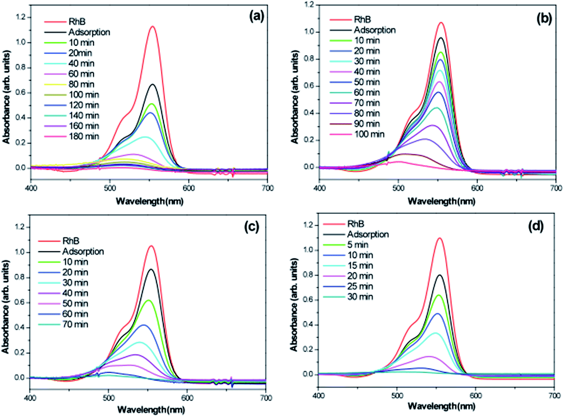 | ||
| Fig. 14 Absorption spectra of a RhB solution as a function of the LED light irradiation time in the presence of (a) WO3; (b) WO3·0.01Ag; (c) WO3·0.05Ag and (d) WO3·0.20Ag. | ||
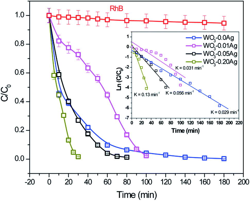 | ||
| Fig. 15 Photocatalytic degradation efficiency of RhB dye solution in the presence of different photocatalysts under LED light irradiation. The inset shown degradation kinetic of RhB dye solution with photocatalysts under LED light irradiation. | ||
Based on the above photocatalytic results, a mechanism for the photodegradation of RhB dye solution over the WO3·0.20Ag hierarchical architecture is proposed, as following (Schemes 1 and 2).
 | ||
| Scheme 1 Schematic energy band levels for the Ag/WO3 metal–semiconductor interface after contact. | ||
 | ||
| Scheme 2 Schematic representation of photocatalytic mechanism for degradation of dye pollutants. (i) Electron-hole pairs photogeneration, charge transfer and carriers separation process, (ii) oxygen superoxide ion and the hydroxyl radical generation process and (iii) degradation process of the dye pollutants. | ||
The Scheme 1 shown energy band levels for the Ag/WO3 metal–semiconductor interface after contact. Considering that the silver work function (ΦAgM) is lower than the semiconductor electronaffinity  the semiconductor acquires a negative charge and shifts downward at the interface.57 As a result a space charge region in which the electron concentration is greater than the concentration of ionized donor atoms is formed. The excess electron concentration at the interface supports the contact potential between the two materials. EF and
  stands for Fermi level and band gap energy of WO3. Consequently, when WO3–0.20Ag catalyst are illuminated under 467 nm, photogenerated electrons (e−) in the valence band (VB) of WO3–0.20Ag can be excited to the conduction band (CB); simultaneously, the same amount of holes (h+) are generated in the valence band (VB). Moreover, the energy bands bending in the space charge region (Scheme 1) facilitates the rapid transfer of the photogenerated electrons from CBWO3 to Ag nanoparticles (NPs); Ag NPs acts as an electron's reservoir for the process. Additionally, Ag NPs shown known surface plasmon resonance (SPR) effect, which extended and enhanced the light absorption and enhanced the separation efficiency of the photogenerated electron-hole pairs.61–63 As a results, these photogenerated electrons (e−) and electrons from the reservoir on the Ag NPs could be trapped by O2 molecules in the solution and generate the ˙O2− radical specie.64–67 On the other hand, the photogenerated holes (h+) are capable to react with H2O or OH− molecules, generating the ˙OH radical specie (Scheme 2). As a result, the RhB dye molecules can be effectively photodegraded by these strong oxidants radical species.
Finally, these results indicate that the number of photogenerated h+ and e− in the WO3–0.20Ag, responsible to produce the ˙OH and ˙O2− oxidants radical species, respectively, was very large compared with that of h+ and e− generated from WO3–0.0Ag, WO3–0.01Ag and WO3–0.05Ag catalyst.
4. Conclusions
In this study, we have synthesized Ag NPs decorated WO3 3D hierarchical structures by a one-step facile hydrothermal method in the absence surfactant. In addition, was found that Ag NPs amount is the critical factor in the formation of various novel and complex WO3 3D hierarchical architectures self-assembled, i.e. flower-like (pure WO3 and WO3·0.01Ag), football-like (WO3·0.05Ag) and spiky ball-like (WO3·0.20Ag). FEG-SEM and HRTEM analyses showed that Ag NPs are present on the surface of WO3 3D hierarchical architecture. The as-prepared 3D hierarchical architectures self-assembled displayed different photocatalytic efficiency for decomposition of RhB dye solution under the 467 nm illumination. The as-prepared WO3·0.20Ag 3D hierarchical structure presents a better photodegradation of RhB dye solution than that of the individual WO3 3D hierarchical structure, which is attributed to a engineering heterojuction between Ag NPs and WO3 semiconductor, which could enhanced the light absorption producing more charges carries (photoexcited electrons) and suppress the photogenerated electron-hole pairs recombination rate. This work may provide a facile alternative route for the shape-controlled synthesis of WO3 3D hierarchical structures and potential catalyst for spiky ball-like WO3·0.20Ag hierarchical architecture in the treatment of the wastewater remediation.Conflicts of interest
There are no conflicts to declare.Acknowledgements
This study was financially supported by the Brazilian agencies FAPESP and CNPq. In particular, we would like to acknowledge CEPID/CMDMC/CDMF/INCTMN, FAPESP processes no. 11/20536-7, 12/14106-2, and 13/07296-2 and CNPq process no. 470147/2012-1.References
- M. Fang, G. Dong, R. Wei and J. C. Ho, Adv. Energy Mater., 2017, 7, 1700559 CrossRef
.
- G. Zhang, Z. Zhao, H. Tan, H. Zhao, D. Qu, M. Zheng, W. Yu and Z. Sun, RSC Adv., 2015, 5, 21237 RSC
- Y. Sun, L. Wang, X. Yu and K. Chen, CrystEngComm, 2012, 14, 3199 RSC
- D. Chen, T. Li, Q. Chen, J. Gao, B. Fan, J. Li, X. Li, R. Zhang, J. Sund and L. Gao, Nanoscale, 2012, 4, 5431 RSC
- A. P. Dral and J. E. ten Elshof, Sens. Actuators, B, 2018, 272, 369 CrossRef CAS
- J. Xu, Z. Wang, W. Li, X. Zhang, D. He and X. Xiao, Nanoscale Res. Lett., 2017, 12, 54 CrossRef PubMed
- W. Xia, C. Mei, X. Zeng, G. Fan, J. Lu, X. Meng and X. Shen, ACS Appl. Mater. Interfaces, 2015, 7, 11824 CrossRef CAS PubMed
- H. Ren, X. Gou and Q. Yang, RSC Adv., 2017, 7, 12085 RSC
- Z. Jia, F. Lyu, L. C. Zhang, S. Zeng, S. X. Liang, Y. Y. Li and J. Lu, Sci. Rep., 2019, 9, 7636 CrossRef CAS PubMed
- H. Lee, J.-D. Liao, K. Sivashanmugan, B. H. Liu, W.-e Fu, C.-C. Chen, G. D. Chen and Y.-D. Juang, Nanomaterials, 2018, 8, 402 CrossRef PubMed
- L. Tzounis, R. Contreras-Caceres, L. Schellkopf, D. Jehnichen, D. Fischer, C. Cai, P. Uhlmann and M. Stamm, RSC Adv., 2014, 34, 17846 RSC
- S. Stankic, S. Suman, F. Haque and J. Vidic, J. Nanobiotechnol., 2016, 14, 73 CrossRef PubMed
- M. Abd-Ellah, S. Bazargan, J. P. Thomas, M. A. Rahman, S. Srivastava, X. Wang, N. F. Heinig and K. T. Leung, Adv. Electron. Mater., 2015, 1, 1500032 CrossRef
- S. Wu, H. He, X. Li, C. Yang, G. Zeng, B. Wu, S. He and L. Lu, Chem. Eng. J., 2018, 341, 126 CrossRef CAS
- Y. Lin, S. Wu, X. Li, X. Wu, C. Yang, G. Zeng, Y. Peng, Q. Zhou and L. Lu, Appl. Catal., B, 2018, 227, 557 CrossRef CAS
- X. Liu, J. Iocozzia, Y. Wang, X. Cui, Y. Chen, S. Zhao, Z. Li and Z. Lin, Energy Environ. Sci., 2017, 10, 402 RSC
- P. R. Sajanlal, T. S. Sreeprasad, A. K. Samal and T. Pradeep, Nano Rev., 2011, 2, 1 Search PubMed
- D. G. Shchukin and G. B. Sukrorukov, Adv. Mater., 2004, 16, 671 CrossRef CAS
- J. Y. Zheng, Z. Haider, T. K. Van, A. U. Pawar, M. J. Kang, C. W. Kim and Y. S. Kang, CrystEngComm, 2015, 17, 6070 RSC
- J. Li, J. Huang, J. Wu, L. Cao, Q. Li and K. Yanagisawa, CrystEngComm, 2013, 15, 7904 RSC
- H. Hossainian, M. Salavati-Niasari and M. Bazarganipour, J. Mol. Liq., 2016, 220, 747 CrossRef CAS
- T. C. M. Vinh Do, D. Q. Nguyen, K. T. Nguyen and P. H. Le, Materials, 2019, 12, 2434 CrossRef PubMed
- P. Dong, G. Hou, X. Xi, R. Shao and F. Dong, Environ. Sci.: Nano, 2017, 4, 539 RSC
- K. Ghosh, A. Roy, S. Tripathi, S. Ghule, A. K. Singh and N. Ravishanka, J. Mater. Chem. C, 2017, 5, 7307 RSC
- S. Girisk Kumar and K. S. R. Koteswara Rao, Appl. Surf. Sci., 2015, 355, 939 CrossRef
- J. Huang, D. Ma, F. Chen, D. Chen, M. Bai, K. Xu and Y. Zhao, ACS Appl. Mater. Interfaces, 2017, 9, 7436 CrossRef CAS PubMed
- S. Girisk Kumar and K. S. R. Koteswara, Appl. Surf. Sci., 2017, 391, 124 CrossRef
- Q. Xiang, G. F. Meng, H. B. Zhao, Y. Zhang, H. Li, W. J. Ma and J. Q. Xu, J. Phys. Chem. C, 2010, 114, 2049 CrossRef CAS
- S. S. Acharyya, S. Ghosh and R. Bal, Chem. Commun., 2015, 51, 5998 RSC
- J. Ding, Y. Chai, Q. Liu, X. Liu, J. Ren and W. L. Dai, J. Phys. Chem. C, 2016, 120, 4345 CrossRef CAS
- Q. Xiang, G. F. Meng, H. B. Zhao, Y. Zhang, H. Li, W. J. Ma and J. Q. Xu, J. Phys. Chem. C, 2010, 114, 2049 CrossRef CAS
- X. He, C. Hu, Y. Xi, K. Zhang and H. Hu, Mater. Res. Bull., 2014, 50, 91 CrossRef CAS
- C. Balazsi and J. Pfeifer, Solid State Ionics, 2002, 151, 353 CrossRef CAS
- A. Phuruangrat, D. J. Ham, S. J. Hong, S. Thongtema and J. S. Lee, J. Mater. Chem., 2010, 10, 1683 RSC
- Z. Gu, Y. Ma, W. Yang, G. Zhang and J. Yao, Chem. Commun., 2005, 41, 3597 RSC
- A. C. Marques, L. Santos, M. N. Costa, J. M. Dantas and P. Duarte, et al., Sci. Rep., 2015, 5, 9910–9917 CrossRef CAS PubMed
- S. Bai, K. Zhang, X. Shu, S. Chen, R. Luo, D. Li and A. Chen, CrystEngComm, 2014, 16, 10210 RSC
- N. Dirany, M. Arab, V. Madigou, Ch. Leroux and J. R. Gavarri, RSC Adv., 2016, 6, 69615 RSC
- M. Gotic, M. Ivanda, S. Popovic and S. Music, Mater. Sci. Eng., B, 2000, 77, 193 CrossRef
- B. Ingham, S. V. Chong and J. L. Tallon, J. Phys. Chem. B, 2005, 109, 4936 CrossRef CAS PubMed
- J. Diaz-Reyes, V. Dorantes-garcia, A. Pérez-Benitez and J. A. Balderas-Lopes, Superficies Vacio, 2008, 21, 12 Search PubMed
- S. Rajagopal, D. Nataraj, D. Mangalaraj, Y. Djaoued, J. Robichaud and O. Y. Khyzhun, Nanoscale Res. Lett., 2009, 4, 1335 CrossRef CAS PubMed
- M. F. Daniel, B. Desbat, J. C. Lassegues, B. Gerand and M. Figlarz, J. Solid State Chem., 1987, 67, 235 CrossRef CAS
- J. T. Szymansk and A. C. Roberts, Can. Mineral., 1984, 22, 681 Search PubMed
- C. Guéry, C. Choquet, F. Dujeancourt, J. M. Tarascon and J. C. Lassègues, J. Solid State Electrochem., 1997, 1, 199 CrossRef
- L. M. Kuti, S. S. Bhella and V. Thangadurai, Inorg. Chem., 2009, 48, 6804 CrossRef CAS PubMed
- L. Zhou, J. Zou, M. Yu, P. Lu, J. Wei, Y. Qian, Y. Wang and C. Yu, Cryst. Growth Des., 2008, 8, 3993 CrossRef CAS
- L. Santos, J. P. Neto, A. Crespo, D. Nunes, N. Costa and I. M. Fonseca, et al., ACS Appl. Mater. Interfaces, 2014, 6, 12226 CrossRef CAS PubMed
- F. Xu, Y. Yao, D. Bai, R. Xu, J. Mei, D. Wu, Z. Ga and K. Jiang, RSC Adv., 2015, 5, 60339 RSC
- D. Chen, T. Li, Q. Chen, J. Gao, B. Fan, J. Li, X. Li, R. Zhang, J. Sun and L. Gao, Nanoscale, 2012, 4, 5431 RSC
- M. Ahmadi, R. Younesi and M. J. F. Guinel, J. Mater. Res., 2014, 29, 1424 CrossRef CAS
- P. Dong, B. Yang, C. Liu, F. Xu, X. Xi, G. Hou and R. Shao, RSC Adv., 2017, 7, 947 RSC
- H. Ren, X. Goub and Q. Yang, RSC Adv., 2017, 7, 12085 RSC
- R. R. Kharade, S. S. Mali, S. P. Patil, K. R. Patil and M. G. Gang, et al., Electrochim. Acta, 2013, 102, 358 CrossRef CAS
- S. M. Harshulkhan, K. Janaki, G. Velraj, R. S. Ganapathy and S. Krishnaraj, J. Mater. Sci.: Mater. Electron., 2016, 27, 3158 CrossRef
- P. Dong, B. Yang, C. Liu, F. Xu, X. Xi, G. Hou and R. Shao, RSC Adv., 2017, 7, 947 RSC
- J. Jiang, H. Li and L. Z. Zhang, Chem.–Eur. J., 2012, 18, 6360 CrossRef CAS PubMed
- Y. Ren, C. Li, Q. Xu, J. Yan, Y. Li, P. Yuan, H. Xia, C. Niu, X. Yang and Y. Jia, Appl. Catal., B, 2019, 245, 648 CrossRef CAS
- Y. Lin, H. Liu, C. Yang, X. Wu, C. Du, L. Jiang and Y. Zhong, Appl. Catal., B, 2020, 264, 118479 CrossRef
- Y. Lin, X. Wu, Y. Han, C. Yang, Y. Ma, C. Du, Q. Teng, H. Liu and Y. Zhong, Appl. Catal., B, 2019, 258, 117969 CrossRef CAS
- D. P. Sahoo, S. Patnaik and K. Parida, ACS Omega, 2019, 4, 14721 CrossRef CAS PubMed
- D. Chen, T. Li, Q. Chen, J. Gao, B. Fan, J. Li, X. Li, R. Zhang, J. Sund and L. Gao, Nanoscale, 2012, 4, 5431 RSC
- V. Kavinkumar, A. Verma, S. Masilamani, S. Kumar, K. Jothivenkatachalam and Y. –P. Fu, Dalton Trans., 2019, 48, 10235 RSC
- T. Wang, J. Lang, Y. Zhao, Y. Su, Y. Zhao and X. Wang, CrystEngComm, 2015, 17, 6651 RSC
- H. Wang, X. Liu and S. Han, CrystEngComm, 2016, 18, 1933 RSC
- Y. Bua, Z. Chena and C. Sun, Appl. Catal., B, 2015, 179, 363 CrossRef
- C. Chai, J. Liu, Y. Wang, X. Zhang, D. Duan, C. Fan and Y. Wang, Appl. Phys. A, 2019, 125, 96 CrossRef
Footnote |
| † Electronic supplementary information (ESI) available. See DOI: 10.1039/c9ra10173j |
| This journal is © The Royal Society of Chemistry 2020 |