DOI:
10.1039/C9RA10100D
(Paper)
RSC Adv., 2020,
10, 698-704
Synthesis of Ag and AgCl co-doped ZIF-8 hybrid photocatalysts with enhanced photocatalytic activity through a synergistic effect
Received
3rd December 2019
, Accepted 12th December 2019
First published on 2nd January 2020
Abstract
Recently, Ag/AgCl composites with different structures have been widely studied and used as photocatalysts to degrade dye pollutants, due to their high separation efficiency of electron–hole pairs under visible light irradiation. Herein, we adopted a nucleation, precipitation, growth and photoreduction method to prepare Ag and AgCl co-doped ZIF-8 hybrid photocatalysts and explored the influence of Ag content on their physical and chemical properties. All as-prepared samples were characterized by X-ray diffraction (XRD), scanning electron microscopy (SEM), transmission electron microscopy (TEM), Brunauer–Emmett–Teller (BET) measurements, energy dispersive spectroscopy (EDS), UV-vis diffuse reflectance and X-ray photoelectron spectroscopy (XPS). XRD indicated that ZIF-8 and AgCl were formed and some of the AgCl was reduced into Ag0 after 30 min of UV light irradiation. SEM and TEM images verified that Ag/AgCl nanoparticles were inlaid in the body of ZIF-8 and Ag ions could hinder the growth of the ZIF-8 crystal. BET data indicated that Ag/AgCl nanoparticles did not alter the pore size of ZIF-8. The UV-vis diffuse reflectance spectra showed that Ag/AgCl@ZIF-8 has excellent ability to absorb visible light, indicating the high efficiency of the electron–hole pair separation of Ag/AgCl@ZIF-8. Finally, the photocatalytic activities of all of the as-synthesized samples were evaluated by degradation of RhB under visible light irradiation. Ag and AgCl co-doped ZIF-8 hybrid photocatalysts exhibited high photocatalytic activity due to the synergistic effect of ZIF-8, AgCl and Ag. After 60 min of visible light irradiation, Ag/AgCl(15)@ZIF-8 exhibited the best photocatalytic activity and could degrade 99.12% RhB, which was higher than Ag/AgCl (94.24%) and ZIF-8 (5.17%). Additionally, a photocatalytic mechanism for dye pollutant degradation over the Ag and AgCl co-doped ZIF-8 hybrid photocatalysts was proposed.
1. Introduction
Semiconductor photocatalysis has been considered as an efficient way to eliminate the environmental contamination coming from the consumption of energy and dwindling fossil fuels because it can degrade organic pollutants into green matter, such as H2O, and CO2.1 Until now, many photocatalysts, such as TiO2,2 ZnO,3 SnO2 (ref. 4) and ZrO2,5 have been found and used in many fields. Under UV light irradiation, these photocatalysts can be photoexcited and produce strong oxidizing materials to oxidize organic pollutants into nontoxic substances.6 However, most of the semiconductors have large band gaps and can only be excited by UV light. As a result, tremendous effort has been made to develop visible light-driven photocatalysts with high efficiency.7–15
In recent years, metal–organic frameworks (MOFs), constructed from metal clusters and organic linkers, have attracted increasing research attention due to their high surface areas, tunable pore sizes, and high thermal and chemical stability.16 These excellent outstanding features make them potential candidates to be used in gas storage, catalysis, drug delivery, chemical separation, electronic and magnetic materials.17–19 ZIF-8, as one MOF material, is built from Zn2+ and imidazolate organic ligands and has higher thermal and chemical stability than other MOFs.20 However, ZIF-8 has large band gaps and exhibits weak photoresponse under UV light.21 To enhance its photocatalytic efficiency, ZIF-8 is combined with other semiconductors to prepare composite photocatalysts. For instance, Luo and his colleague used TiO2 nanofibers as a support to load ZIF-8 nanoparticles on the surface.22 Due to the effective electron transfer between ZIF-8 and TiO2, the TiO2/ZIF-8 hybrid photocatalysts show higher photocatalytic activity than the TiO2 nanofibers. Yu et al. reported that core–shell ZnO@ZIF-8 nanospheres were synthesized via a self-template method and showed good activity in methylene blue degradation under UV irradiation.23 To take advantage of the sustainable and clean solar energy of sunlight, many researchers have made efforts to develop semiconductor/ZIF-8 hybrid photocatalysts with visible light response. For example, Liu et al. adopted a simple deposition-photoreduction method to prepare a Ag@AgCl/Ag nanofilm/ZIF-8 composite photocatalyst, in which Ag nanofilm was harnessed as a mediator to transfer photo-induced electrons from Ag@AgCl to ZIF-8 to enhance the photocatalytic degradation under visible light irradiation.24 Gao and his colleague reported that ZIF-8 can be used as a support to load Ag/AgCl nanoparticles. Ag/AgCl@ZIF-8 hybrid materials exhibit excellent photocatalytic properties when used as photocatalysts for RhB degradation under visible light irradiation.25 However, Ag+ has great oxidizability and can coordinate with organic ligands to form HAg(IM)2 complexes, which have a negative influence on the special surface area of ZIF-8.26 This “bottleneck” for these photocatalysts makes it hard to meet the requirements of practical applications.
In this paper, we adopted a nucleation, precipitation, growth and photoreduction method to prepare novel Ag/AgCl(x)@ZIF-8 hybrid photocatalysts. ZIF-8 kept its integrity and could avoid being oxidized by Ag+. Ag/AgCl nanoparticles, being synthesized by the reduction of AgCl under UV light, were inlaid in the body of ZIF-8. The photocatalytic activity of the Ag/AgCl(x)@ZIF-8 hybrid photocatalysts was evaluated by degradation of RhB under visible light irradiation. After being carefully researched, Ag/AgCl(15)@ZIF-8 exhibited the highest photocatalytic efficiency and excellent chemical stability. Ag/AgCl(15)@ZIF-8 was able to degrade 99.12% RhB and could degrade 97.16% RhB after four repeated cycles. The synergistic effects of Ag/AgCl nanoparticles to generate excitons and the ZIF-8 structure to capture dye molecules endow the Ag and AgCl co-doped ZIF-8 hybrid photocatalysts with superior photocatalytic activity in the degradation of organic pollutants.
2. Experimental
Materials
Silver nitrate (AgNO3, 99%), zinc chloride (ZnCl2, 99%), 2-methylimidazole (C4H6N2, 99%), rhodamine B (RhB, 99%) and methanol (CH3OH, 99%) were all analytical reagents and purchased from Sinopharm Chemical Reagent Co. Ltd. All reagents were directly used as received without further purification. Distilled water was used in this experiment.
Synthesis of Ag/AgCl@ZIF-8 hybrid photocatalysts
Ag/AgCl@ZIF-8 hybrid photocatalysts were synthesized by modifying the methods of Schejns et al. and McEvoy et al.27,28 Firstly, 10 mmol ZnCl2 was dispersed in 100 mL methanol and kept stirring vigorously for 30 min until it was dissolved absolutely. Then, 100 mL methanol, containing 80 mmol 2-methylimidazole, was added dropwise into the above solution and intensively stirred for 30 min to form a homogeneous milky suspension. Then, 40 mL of methanol, containing 3 mL of H2O and X mmol of AgNO3 (X is 5, 10, 15 and 20, respectively), was injected slowly into the above milky solution and kept stirring for 24 h under dark conditions. After that, it was centrifuged and washed with ethanol and distilled water to obtain the AgCl(x)@ZIF-8 composites. Finally, 1 g of the AgCl(x)@ZIF-8 composites was dispersed in 100 mL of distilled water and kept stirring vigorously for 30 min under UV light (λ ≤ 400 nm, from a 500 W mercury lamp) to prepare Ag/AgCl(x)@ZIF-8 hybrid photocatalysts. Ag/AgCl@ZIF-8 was centrifuged and dried in air at 60 °C.
Characterization
X-ray diffractometry (XRD) patterns were acquired on a Bruker-AXS D8 advance with Cu-Kα radiation in the range of 5–80° (2θ). Scanning electron microscopy (SEM) images were taken on a Hitachi SU70 scanning electron microscope at an accelerating voltage of 10 kV. The transmission electron microscope (TEM) pictures were obtained on a Tecnai F30 microscope operated at 100 kV. The mapping images were obtained from an energy dispersive spectrometer affiliated to the Tecnai F30 microscope. UV-vis diffuse reflectance spectra were recorded on a UV-1901 UV-vis spectrophotometer using BaSO4 as the reference from 250–900 nm. The nitrogen adsorption–desorption isotherms were obtained on TriStarII3020 adsorption apparatus at −196 °C. Before the sorption measurements, all samples were degassed at 150 °C for 5 h. The average pore size and pore volumes were calculated from the adsorption branches according to the Horvath-Kawazoe (HK) method.
Evaluation of photocatalytic activity
The photocatalytic activity of all as-synthesized samples was evaluated by the degradation of an aqueous RhB solution under a 500 W xenon lamp equipped with a UV cut-off filter (λ > 400 nm). In a typical procedure, 50 mg of all of the as-synthesized samples was dispersed in 100 mL of RhB solution (10 ppm) in a quartz photochemical reactor at room temperature. To eliminate the influence of adsorption of the sample, the suspension was stirred in the dark for 30 min before the irradiation. After that, the suspension was exposed under visible light, which was irradiated from a 500 W xenon lamp equipped with a 400 nm cut-off filter. Every 15 min, 5 mL of the suspension was withdrawn from the reactor, centrifuged at 10![[thin space (1/6-em)]](https://www.rsc.org/images/entities/char_2009.gif) 000 rpm for 2 min to remove the photocatalyst and then analyzed by a UV-1901 UV-vis spectrophotometer to calculate the residual dye concentration in the solution. The removal efficiency (DR) of RhB can be calculated using the following formula:
000 rpm for 2 min to remove the photocatalyst and then analyzed by a UV-1901 UV-vis spectrophotometer to calculate the residual dye concentration in the solution. The removal efficiency (DR) of RhB can be calculated using the following formula:| |
 | (1) |
where Co denotes the initial concentration of RhB, and Ct is the concentration of RhB at time t.
3. Results and discussion
Fig. 1 presents the XRD patterns of all of the as-synthesized samples. Fig. 1a is the XRD pattern of the as-synthesized Ag/AgCl. It shows diffraction peaks at 27.8°, 32.2°, 46.2°, 54.8°, 57.4°, 67.4°, 74.4° and 76.7°, which correspond to the (111), (200), (220), (311), (222), (400), (331) and (420) planes of cubic phase AgCl (JCPDS no. 31-1238), respectively.29 In addition, there is also a peak at 38.1°, which is ascribed to the (111) plane of Ag (JCPDS file: 65-2871).30 This indicates that Ag0 nanospecies are formed with AgCl. This can be attributed to the decomposition of AgCl under UV light irradiation. Fig. 1b is the XRD pattern of the as-synthesized ZIF-8. It exhibits peaks at 7.38°, 10.42°, 14.75°, 16.50°, 18.08° and 19.53°, which can be indexed to the (011), (002), (112), (022), (013), (222) and (123) planes of ZIF-8, respectively.31 Fig. 1c–f are the XRD patterns of Ag/AgCl(5)@ZIF-8, Ag/AgCl(10)@ZIF-8, Ag/AgCl(15)@ZIF-8 and Ag/AgCl(20)@ZIF-8, respectively. They all show characteristic peaks of ZIF-8, AgCl and Ag0. The peak intensities of Ag0 and AgCl increase with increasing Ag content. This suggests that the Ag0 and AgCl content also increases. Furthermore, no other peaks are detected, indicating that the Ag/AgCl(x)@ZIF-8 photocatalysts are solely composed of Ag0, AgCl and ZIF-8.
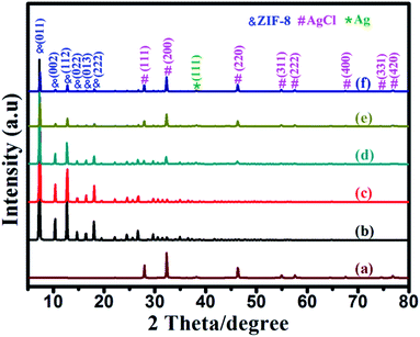 |
| | Fig. 1 The XRD patterns of (a) Ag/AgCl, (b) ZIF-8, (c) Ag/AgCl(5)@ZIF-8, (d) Ag/AgCl(10)@ZIF-8, (e) Ag/AgCl(15)@ZIF-8, and (f) Ag/AgCl(20)@ZIF-8. | |
The influence of Ag+ ions on the size and morphology of the ZIF-8 nanoparticles was estimated by scanning electron microscopy (SEM). All samples were obtained after 24 h of reaction and the results are shown in Fig. 2. As we known, the growth of ZIF-8 crystals evolves with time from cubes exposing 6{100} faces to rhombic dodecahedra exposing 12{110} faces, most likely the stable equilibrium morphology of ZIF-8 (Fig. 3).32 After 24 h of reaction, the ZIF-8 nanoparticles show an average size of 600 ± 24 nm and exhibit the shape of a rhombic dodecahedron exposing 12{110} faces (Fig. 2a). With 5 mmol AgNO3, ZIF-8 also exhibits well-defined truncated rhombic dodecahedral crystals and its particle size decreases to 550 nm (Fig. 2b). Adding 10 mmol AgNO3, the average size of the ZIF-8 nanoparticles is 400 ± 18 nm and a few Ag/AgCl nanoparticles are formed and inlaid in the ZIF-8 nanoparticles (Fig. 2c). With 15 mmol AgNO3, well-defined shrunken cubic crystals with an average size of 300 ± 22 nm are obtained (Fig. 2d). Many Ag/AgCl nanoparticles hybridize with the ZIF-8 crystals. Adding 20 mmol AgNO3, some Ag/AgCl nanoparticles with an average size of 200 ± 35 nm are formed and adhere on the surface of the ZIF-8. The particle size of ZIF-8 decreases to 200 ± 20 nm (Fig. 2e). Fig. 2f is an image of Ag/AgCl. Some Ag/AgCl nanoparticles are aggregated together.
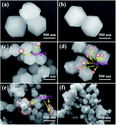 |
| | Fig. 2 SEM images of (a) ZIF-8, (b) Ag/AgCl(5)@ZIF-8, (c) Ag/AgCl(10)@ZIF-8, (d) Ag/AgCl(15)@ZIF-8, (e) Ag/AgCl(20)@ZIF-8, and (f) Ag/AgCl. | |
 |
| | Fig. 3 Illustration of the crystal morphology evolution with time: (a) cube, (b) cube with truncated edges, (c) rhombic dodecahedron with truncated corners, and (d) rhombic dodecahedron. | |
In order to investigate the internal structure of Ag/AgCl@ZIF-8, Ag/AgCl(5)@ZIF-8 was chosen as the sample to be analyzed by transmission electron microscopy. The results are shown in Fig. 4. Fig. 4a is the low magnification image of Ag/AgCl(5)@ZIF-8. Ag/AgCl(5)@ZIF-8 exhibits the typical morphology of a rhombic dodecahedron, which is in accordance with the SEM images (Fig. 2b). Fig. 4b is the high magnification image of Ag/AgCl(5)@ZIF-8. From the HRTEM image, we can clearly observe the characteristic lattice fringes of 0.205 and 0.318 nm, which are ascribed to the (200) and (111) planes of Ag and AgCl, respectively.33,34 Ag/AgCl nanoparticles are well inlaid in the porous metal organic framework. Ag/AgCl(5)@ZIF-8 was evaluated by an energy dispersive spectrometer affiliated to a Tecnai F30 microscope. The EDS mappings of Ag/AgCl(5)@ZIF-8 are shown in Fig. 5. Ag/AgCl(5)@ZIF-8 is composed of elemental Zn, N, C, Al and Cl. Ag and Cl are well dispersed on ZIF-8.
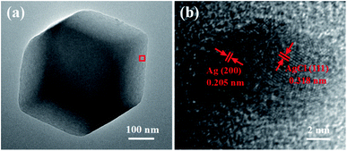 |
| | Fig. 4 (a) Low magnification TEM and (b) HRTEM images of Ag/AgCl(5)@ZIF-8. | |
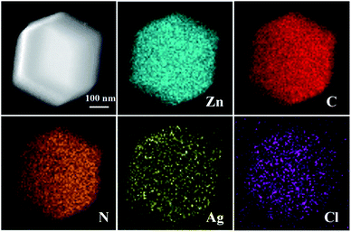 |
| | Fig. 5 EDS mappings of Ag/AgCl(5)@ZIF-8. | |
Fig. 6 shows the N2 adsorption–desorption isotherms of ZIF-8, Ag/AgCl(5)@ZIF-8, Ag/AgCl(10)@ZIF-8, Ag/AgCl(15)@ZIF-8, Ag/AgCl(20)@ZIF-8, and Ag/AgCl. ZIF-8, Ag/AgCl(5)@ZIF-8, Ag/AgCl(10)@ZIF-8, Ag/AgCl(15)@ZIF-8, and Ag/AgCl(20)@ZIF-8 show a high sorption step in the P/P0 <0.1 region, which is ascribed to a type I isotherm. This indicates that they exhibit microporosity.35 More interestingly, when ZIF-8 is loaded with Ag/AgCl, its N2 adsorption decreases. This is in accordance with the specific surface area and pore volume shown in Table 1. It may be attributed to the different catalytic extent of ZIF-8. However, the loading of Ag/AgCl did not change the pore size of ZIF-8, being consistent with the fact that Ag/AgCl nanoparticles were just inlaid in the ZIF-8 nanoparticles.
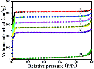 |
| | Fig. 6 N2 adsorption–desorption isotherms of (a) ZIF-8, (b) Ag/AgCl(5)@ZIF-8, (c) Ag/AgCl(10)@ZIF-8, (d) Ag/AgCl(15)@ZIF-8, (e) Ag/AgCl(20)@ZIF-8, and (f) Ag/AgCl. | |
Table 1 Textural properties of all samplesa
| Sample |
SBET (m2 g−1) |
Stma (m2 g−1) |
Vtotal (mL g−1) |
DHK (nm) |
| SBET: BET surface area. Stma: T-plot micropore area. Vtotal: T-plot micropore volume. DHK: average pore diameter. |
| ZIF-8 |
1148 |
1106 |
0.67 |
1.15 |
| Ag/AgCl(5)@ZIF-8 |
985 |
942 |
0.61 |
1.15 |
| Ag/AgCl(10)@ZIF-8 |
898 |
865 |
0.56 |
1.15 |
| Ag/AgCl(15)@ZIF-8 |
786 |
745 |
0.47 |
1.15 |
| Ag/AgCl(20)@ZIF-8 |
697 |
651 |
0.42 |
1.15 |
| Ag/AgCl |
53 |
41 |
0.03 |
13.45 |
Fig. 7 shows the UV-vis diffuse reflectance spectra of all of the as-synthesized samples. ZIF-8 exhibits a strong absorption at about 248 nm, which corresponds to the characteristic absorption peak of ZIF-8. In contrast to ZIF-8, Ag/AgCl(x)@ZIF-8 has two new strong adsorption peaks in the ultraviolet and visible regions. The strong absorption from 280 to 335 nm is ascribed to AgCl, and the other strong absorption from 442 to 700 nm is due to the SPR of Ag nanoparticles on the surface of Ag/AgCl(x)@ZIF-8. From the previous research, we know that the band gap energy can be calculated using the formula: Eg = 1239.8/λg (where λg is the absorption edge).36 The band gap energies of ZIF-8, AgCl and Ag are 5.00, 3.25 and 0.93 eV, respectively. More interestingly, with an increase in Ag/AgCl content, Ag/AgCl(x)@ZIF-8 exhibits stronger production of more and more electron–hole pairs under visible light irradiation.37 This is helpful to enhance the photocatalytic activity of Ag/AgCl@ZIF-8 and allow the use of sunlight to degrade organic dye pollutants.
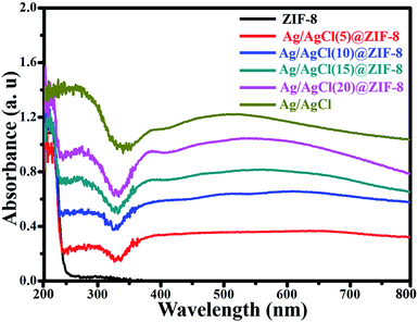 |
| | Fig. 7 UV-vis spectra of ZIF-8, Ag/AgCl(5)@ZIF-8, Ag/AgCl(10)@ZIF-8, Ag/AgCl(15)@ZIF-8, Ag/AgCl(20)@ZIF-8 and Ag/AgCl. | |
Recent studies have indicated that RhB is a carcinogenic contaminant and harmful to human health. Thus, the effective degradation of toxic RhB molecules into nontoxic small molecules will be good for both environment protection and human health. In this experiment, we adopted RhB solution as a probe to evaluate the photocatalytic activity of all of the as-synthesized samples under visible light irradiation. In order to eliminate the influence of the adsorption by the photocatalyst, the photocatalyst was dispersed in RhB solution and kept stirring for 30 min in the dark to get a desorption and adsorption equilibrium before irradiation under visible light. The results are shown in Fig. 8. From Fig. 8, it can be observed that 65.77%, 48.96%, 39.18%, 31.84%, 24.36% and 7.36% RhB was absorbed by ZIF-8, Ag/AgCl(5)@ZIF-8, Ag/AgCl(10)@ZIF-8, Ag/AgCl(15)@ZIF-8, Ag/AgCl(20)@ZIF-8 and Ag/AgCl, respectively. This is ascribed to the large surface are of ZIF-8. After 60 min of visible light irradiation, only 4.23% RhB was degraded in the absence of photocatalyst and 5.17% RhB was degraded by pure ZIF-8. This indicates that the self-photolysis of RhB is negligible and ZIF-8 cannot degrade RhB under visible light. When ZIF-8 was combined with Ag/AgCl, it exhibited excellent photocatalytic activity. Ag/AgCl(5)@ZIF-8 can degrade 80.18% RhB after 60 min of visible light irradiation. More interestingly, the photocatalytic activity of Ag/AgCl@ZIF-8 first enhances and then weakens with the increase of Ag content. The photocatalytic degradation efficiency of Ag/AgCl(10)@ZIF-8, Ag/AgCl(15)@ZIF-8, Ag/AgCl(20)@ZIF-8 and Ag/AgCl is 91.26%, 99.12%, 96.57% and 94.24%, respectively. Ag/AgCl(15)@ZIF-8 exhibits the highest photocatalytic activity.
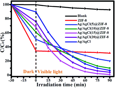 |
| | Fig. 8 The photocatalytic degradation of RhB with ZIF-8, Ag/AgCl(5)@ZIF-8, Ag/AgCl(10)@ZIF-8, Ag/AgCl(15)@ZIF-8, and Ag/AgCl(20)@ZIF-8. | |
Fig. 9 shows the photodegradation dynamic curves over all of the as-synthesized samples. Due to the low concentration of RhB, the kinetics of the photocatalytic reactions approximate a first order reaction and can be expressed by the following formula: ln(Co/Ct) = kapp. Ct is the concentration of RhB at irradiation time t. Co is the initial concentration of RhB. kapp is the apparent reaction rate constant, which can be obtained from the slope of the linear correlation. It can be observed that Ag/AgCl(15)@ZIF-8 exhibits the highest kapp value of 0.049 min−1, which is about 4.5, 2.3, 1.6 and 1.5 times higher than that of Ag/AgCl(5)@ZIF-8 (kapp = 0.011 min−1), Ag/AgCl(10)@ZIF-8 (kapp = 0.021 min−1), Ag/AgCl(20)@ZIF-8 (kapp = 0.030 min−1) and Ag/AgCl (kapp = 0.032 min−1), respectively. The high photocatalytic activity of Ag/AgCl(15)@ZIF-8 can be attributed to the synergistic effect of Ag0, AgCl and ZIF-8.
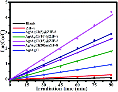 |
| | Fig. 9 The first-order kinetics of RhB degradation in the presence of ZIF-8, Ag/AgCl(5)@ZIF-8, Ag/AgCl(10)@ZIF-8, Ag/AgCl(15)@ZIF-8, and Ag/AgCl(20)@ZIF-8. | |
The photostability of Ag/AgCl@ZIF-8 is very important when it is used as a photocatalyst to degrade organic dye pollutants. Here, Ag/AgCl(15)@ZIF-8 was chosen as the specimen to degrade RhB under visible light for four repeated cycles. The results are shown in Fig. 10.
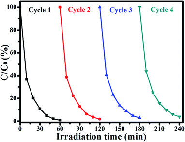 |
| | Fig. 10 Four photocatalytic degradation cycles of RhB using Ag/AgCl(15)@ZIF-8 under visible light irradiation. | |
In the first cycle, Ag/AgCl(15)@ZIF-8 can degrade 99.12% RhB after 60 min of visible light irradiation. Then, the Ag/AgCl(15)@ZIF-8 nanoparticles were collected by centrifugation, washed with distilled water and dried at 60 °C. After four repeated cycles, the photocatalytic efficiency of Ag/AgCl(15)@ZIF-8 is 97.16%. Compared with the first degradation reaction, the photocatalytic efficiency of Ag/AgCl(15)@ZIF-8 is only reduced by 1.96%. Furthermore, the characteristic peaks of Ag/AgCl(15)@ZIF-8 after four photocatalytic degradation cycles of RhB are almost the same as for the original Ag/AgCl(15)@ZIF-8 (Fig. 11). This confirms that Ag/AgCl(15)@ZIF-8 has remarkable reproducibility and long-term stability. The slight reduction of the degradation rate may be due to the inevitable loss of the Ag/AgCl(15)@ZIF-8 nanoparticles during the washing process.
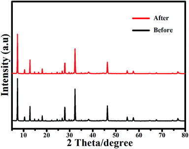 |
| | Fig. 11 The XRD patterns of Ag/AgCl(15)@ZIF-8 before and after four photocatalytic degradation cycles of RhB. | |
A schematic diagram of the degradation of RhB by Ag/AgCl@ZIF-8 under visible light irradiation is shown in Fig. 12. ZIF-8 has a high specific surface area. It can absorb RhB molecules on its surface to form a layer of high concentration RhB. According to the previous research, the conduction band (CB) and valence band (VB) potentials of AgCl are −0.06 and 3.19 eV, respectively.38 AgCl cannot be directly excited by visible light because of its large band gap (3.25 eV). However, Ag has strong SPR properties. Therefore, it can directly absorb visible light. Under visible light irradiation, Ag nanoparticles, contained in Ag/AgCl, can be excited to produce plasmon-induced electrons, which can be easily transferred to the conduction band of AgCl and combine with the adsorbed O2 to generate active species ·O2−. The plasmon-induced holes left on the surface of the Ag nanoparticles can incorporate with OH− to form ·OH. The formed ·O2− and ·OH as the main active species have high oxidation ability and can directly oxidize RhB into inorganic compounds. The elementary reaction equations are expressed as follows:
| | |
RhB + Ag/AgCl@ZIF-8 ↔ (RhB + Ag/AgCl@ZIF-8)adsorption
| (2) |
| | |
Ag/AgCl + hv → e− + h+
| (3) |
| | |
O2− + (RhB + Ag/AgCl@ZIF-8)adsorption → degradation products
| (6) |
| | |
·OH + (RhB + Ag/AgCl@ZIF-8)adsorption → degradation products
| (7) |
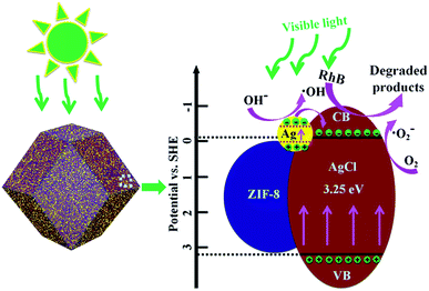 |
| | Fig. 12 A schematic illustration of Ag/AgCl@ZIF-8 catalyzing RhB degradation. | |
4. Conclusions
In summary, Ag/Ag@ZIF-8 hybrid photocatalysts, containing different amounts of Ag content, were successfully prepared by a nucleation, precipitation, growth and photoreduction method. Ag ions have a great influence on the growth of ZIF-8. After being carefully researched, Ag/AgCl nanoparticles can hinder the growth of ZIF-8 crystals and can be phagocytosed during the growth of ZIF-8 crystals. The UV-vis diffuse reflectance and photocatalytic degradation experimental results show that the Ag/AgCl@ZIF-8 photocatalyst has excellent ability to absorb visible light and can degrade RhB under visible light irradiation efficiently. In addition, the loading of Ag/AgCl on ZIF-8 has a great influence on the photocatalytic activity of the Ag/AgCl@ZIF-8 composites and Ag/AgCl(15)@ZIF-8 was found to exhibit the best photocatalytic activity for the degradation of RhB. After 60 min of visible light irradiation, Ag/AgCl(15)@ZIF-8 can degrade 99.12% RhB and it exhibits the highest kapp value of 0.236 min−1. Furthermore, Ag/AgCl(15)@ZIF-8 has excellent photostability. After four repeated degradation cycles, the photocatalytic efficiency of Ag/AgCl(30)@ZIF-8 is only reduced by 1.96%. The high photocatalytic activity and excellent photostability of Ag/AgCl(15)@ZIF-8 mean that it can be used for the degradation of organic pollutants.
Conflicts of interest
There are no conflicts to declare.
Acknowledgements
The authors thank eceshi (http://www.eceshi.cn) for the BET analysis.
Notes and references
- C. Liang, L. Zhang, H. Guo, C. G. Niu, X. J. Wen, N. Tang, H. Y. Liu, Y. Y. Yang, B. B. Shao and G. M. Zeng, Chem. Eng. J., 2019, 361, 373–386 CrossRef CAS.
- W. K. Jo and T. S. Natarajan, Chem. Eng. J., 2015, 281, 549–565 CrossRef CAS.
- X. B. Yang, J. Chen, H. X. Lai, J. P. Hu, M. Fang and X. T. Luo, RSC Adv., 2017, 7, 38519–38525 RSC.
- Z. J. Li, P. Luan, X. L. Zhang, Y. Qu, F. Raziq, J. S. Wang and L. Q. Jing, Nano Res., 2017, 10, 2321–2331 CrossRef CAS.
- H. Sudrajat, S. Babel, H. Sakai and S. Takizawa, J. Environ. Manage., 2016, 165, 224–234 CrossRef CAS PubMed.
- X. B. Yang, J. Chen, J. P. Hu, S. Y. Zhao, J. Y. Zhao and X. T. Luo, Catal. Sci. Technol., 2018, 8, 573–579 RSC.
- H. Guo, C. G. Niu, D. W. Huang, N. Tang, C. Liang, L. Zhang, X. J. Wen, Y. Yang, W. J. Wang and G. M. Zeng, Chem. Eng. J., 2019, 360, 349–363 CrossRef CAS.
- W. Zhong, S. Shen, S. Feng, Z. Lin, Z. Wang and B. Fang, CrystEngComm, 2018, 7851–7856 RSC.
- G. Liao, J. Fang, S. Li and B. Fang, Nanoscale, 2019, 11, 7062–7096 RSC.
- H. Guo, H. Y. Niu, C. Liang, C. G. Niu, D. W. Huang, L. Zhang, N. Tang, Y. Yang, C. Y. Feng and G. M. Zeng, J. Catal., 2019, 370, 289–303 CrossRef CAS.
- H. Y. Liu, C. Liang, C. G. Niu, D. W. Huang, Y. B. Du, H. Guo, L. Zhang, Y. Y. Yang and G. M. Zeng, Appl. Surf. Sci., 2019, 475, 421–434 CrossRef CAS.
- Y. Yang, C. Zhang, D. Huang, G. Zeng, J. Huang, C. Lai, C. Zhou, W. Wang, H. Guo, W. Xue, R. Deng, M. Cheng and W. Xiong, Appl. Catal., B, 2019, 245, 87–99 CrossRef CAS.
- S. Ye, M. Yan, X. Tan, J. Liang, G. Zeng, H. Wu, B. Song, C. Zhou, Y. Yang and H. Wang, Appl. Catal., B, 2019, 250, 78–88 CrossRef CAS.
- H. Yi, M. Jiang, D. Huang, G. Zeng, C. Lai, L. Qin, C. Zhou, B. Li, X. Liu, M. Cheng, W. Xue, P. Xu and C. Zhang, J. Taiwan Inst. Chem. Eng., 2018, 93, 184–192 CrossRef CAS.
- H. Yi, M. Yan, D. Huang, G. Zeng, C. Lai, M. Li, X. Huo, L. Qin, S. Liu, X. Liu, B. Li, H. Wang, M. Shen, Y. Fu and X. Guo, Appl. Catal., B, 2019, 250, 52–62 CrossRef CAS.
- X. B. Yang, J. Chen, Y. Q. Chen, P. J. Feng, H. X. Lai, J. T. Li and X. T. Luo, Nano-Micro Lett., 2018, 10, 15 CrossRef PubMed.
- C. Y. Gao, H. R. Tian, J. Ai, L. J. Li, S. Dang, Y. Q. Lan and Z. M. Sun, Chem. Commun., 2018, 54, 7093–7094 RSC.
- J. R. Fu, S. Das, G. L. Xing, T. Ben, V. Valtchev and S. L. Qiu, J. Am. Chem. Soc., 2016, 24, 7673–7680 CrossRef PubMed.
- Y. Z. Chen, Z. U. Wang, H. W. Wang, J. L. Lu, S. H. Yu and H. L. Jiang, J. Am. Chem. Soc., 2017, 139, 2035–2044 CrossRef CAS PubMed.
- Y. B. Li, L. H. Wee, A. Volodin, J. A. Martens and I. F. J. Vankelecom, Chem. Commun., 2015, 51, 918–920 RSC.
- H. P. Jing, C. C. Wang, Y. W. Zhang, P. Wang and R. Li, RSC Adv., 2014, 4, 54454–54462 RSC.
- X. Zeng, L. Q. Huang, C. N. Nan, J. S. Wang, J. T. Li and X. T. Luo, ACS Appl. Mater. Interfaces, 2016, 8, 20274–20282 CrossRef CAS PubMed.
- B. Yu, F. F. Wang, W. B. Dong, J. Hou, P. C. Lu and J. B. Gong, Mater. Lett., 2015, 156, 50–53 CrossRef CAS.
- J. X. Liu, R. Li, Y. Y. Hu, Z. H. Jia, Y. F. Wang, Y. W. Wang, X. C. Zhang and C. M. Fan, Appl. Catal., B, 2017, 202, 64–71 CrossRef CAS.
- S. T. Gao, W. H. Liu, N. Z. Shang, C. Feng, Q. H. Wu, Z. Wang and C. Wang, RSC Adv., 2014, 4, 61736–61742 RSC.
- X. B. Yang, Z. D. Wen, Z. L. Wu and X. T. Luo, Inorg. Chem. Front., 2018, 5, 687–693 RSC.
- A. Schejn, L. Balan, V. Falk, L. Aranda, G. Medjahdi and R. Schneider, CrystEngComm, 2014, 16, 4493–4500 RSC.
- J. G. McEvoy, W. Cui and Z. Zhang, Appl. Catal., B, 2014, 144, 702–712 CrossRef.
- B. Cai, J. Wang, S. Y. Gan, D. X. Han, Z. J. Wu and L. Niu, J. Mater. Chem. A, 2014, 2, 5280–5286 RSC.
- Z. D. Zhou, X. W. Peng, L. X. Zhong, L. Wu, X. F. Cao and R. C. Sun, Carbohydr. Polym., 2016, 136, 322–328 CrossRef CAS PubMed.
- Y. C. Pan, Y. Y. Liu, G. F. Zeng, L. Zhao and Z. P. Lai, Chem. Commun., 2011, 47, 2071–2073 RSC.
- J. Cravillon, C. A. Schröder, H. Bux, A. Rothkirch, J. Caro and M. Wiebcke, CrystEngComm, 2012, 14, 492–498 RSC.
- Y. Li, K. Zhou, M. He and J. F. Yao, Synthesis of ZIF-8 and ZIF-67 using mixed-base and their dye adsorption, Microporous Mesoporous Mater., 2016, 234, 287–292 CrossRef CAS.
- X. J. Chen, F. G. Chen, F. L. Liu, X. D. Yan, W. Hu, G. B. Zhang, L. H. Tian, Q. H. Xia and X. B. Chen, Catal. Sci. Technol., 2016, 6, 4184–4191 RSC.
- X. Xiao, W. D. Zhang, J. Y. Yu, Y. J. Sun, Y. X. Zhang and F. Dong, Catal. Sci. Technol., 2016, 6, 5003–5010 RSC.
- R. Long and N. J. English, ChemPhysChem, 2011, 12, 2604–2608 CrossRef CAS PubMed.
- S. T. Gao, W. H. Liu, N. Z. Shang, C. Feng, Q. H. Wu, Z. Wang and C. Wang, RSC Adv., 2014, 4, 61736–61742 RSC.
- X. F. Wang, S. F. Li, Y. Q. Ma, H. G. Yu and J. G. Yu, J. Phys. Chem. C, 2011, 115, 14648–14655 CrossRef CAS.
Footnote |
| † Yanqiu Jing and Qiang Lei contributed equally to this work. |
|
| This journal is © The Royal Society of Chemistry 2020 |
Click here to see how this site uses Cookies. View our privacy policy here.  Open Access Article
 *a,
Qiang Lei†b,
Chun Xiab,
Yu Guanb,
Yide Yangb,
Jixian Heb,
Yang Yangb,
Yonghui Zhangb and
Min Yanb
![[thin space (1/6-em)]](https://www.rsc.org/images/entities/char_2009.gif) 000 rpm for 2 min to remove the photocatalyst and then analyzed by a UV-1901 UV-vis spectrophotometer to calculate the residual dye concentration in the solution. The removal efficiency (DR) of RhB can be calculated using the following formula:
000 rpm for 2 min to remove the photocatalyst and then analyzed by a UV-1901 UV-vis spectrophotometer to calculate the residual dye concentration in the solution. The removal efficiency (DR) of RhB can be calculated using the following formula:


