DOI:
10.1039/C9RA09418K
(Paper)
RSC Adv., 2020,
10, 11233-11243
Mathematical modeling of the reaction of metal oxides with methane†
Received
12th November 2019
, Accepted 12th February 2020
First published on 20th March 2020
Abstract
Methane reduction has attracted substantial interest in recent years because an abundant amount of natural gas has been found and methane possesses a strong reduction ability. However, due to the complexity of the reaction, the reductive-kinetics model has not been developed very well. This work reported a new mathematical model for methane reduction. The model is in a form of explicit functions incorporating many parameters to increase its precision. Particularly, it considers the comparison of methane cracking rate and reaction rate. Both the gas diffusion in the product layer and chemical reaction controlled-kinetics formulae were deduced by considering three kinds of shapes (spherical, cylindrical and lamellar) of particles. Also, by employing two parameters (shape coefficient Sc and equivalent diameter d0), the formulae for the same reduction mechanism could be unified to one formula, which was easier to use. The simulation of the model also considers both isothermal and non-isothermal processes of methane reduction. Furthermore, it can describe the reduction of oxides of varied-valence metals. The kinetics of reduction of metal oxides by methane agrees with the results obtained in the practical system.
1. Introduction
Methane (CH4) as an alternative reducing agent to carbon is widely used in extractive metallurgy, which decreases the operating temperature, diminishes the emission of greenhouse gases and other pollutants such as heavy metals, sulfur dioxide and fly ash,1,2 and has received great attention in the field of metallurgy. Methane can be widely used to reduce iron oxide,3,4 titanium oxide5 and other titanium-containing materials,6,7 nickel oxide,1 celestite,8 tungsten oxide,9 cobalt oxide,10 etc.
To elucidate the experimental data, we specified the technical parameters and made the reduction process more controllable in terms of design and scale-up; it is meaningful and indispensable to establish the mathematical model of the CH4 reduction process. Although many valuable kinetic models of gas–solid reactions have been established, such as Jander's model,11 Carter's model,12 the nucleation and growth model,13,14 and the Ginstling–Brounshtein model,15 unfortunately, the previously mentioned treatments are greatly simplified and these models cannot meet the requirement of today's metallurgical industry development.16 Furthermore, these models cannot be employed to describe methane reduction due to its complexity, for instance, methane cracking occurs during the reaction, especially at a higher temperature. Moreover, two or three reaction interfaces usually appear along the radial direction in the particles during the reduction of polyvalent metal oxides, such as titanium dioxide and this also increases the difficulty of the reaction simulation.
Solving differential equations is the other kind of method for analyzing gas–solid reaction kinetics. By incorporating a series of parameters in the system, the formulae become more accurate, however, the difficulty of solving them is also increased and the numerical solutions are hard to obtain.17
Therefore, a model considering the multiple reaction interfaces is proposed for simulating the reaction between metal oxides and methane in the present study. The developed formulae can be used for modeling the reaction of metal oxides with different shapes as well. In addition, for the chemical reaction controlled conditions, the comparison of the methane cracking rate and reaction rate was incorporated.
2. General mechanism for the reduction of metal oxides by methane
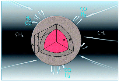
Some hypotheses are proposed first: raw particles possess a uniform diameter and are nonporous, and the diameter remains constant during the reduction. Furthermore, the reduction of metal oxides by methane can be divided into nine different steps
(i) External diffusion of methane.
(ii) Internal diffusion of methane.
(iii) Physical adsorption of CH4.
(iv) Chemical adsorption of CH4.
(v) Chemical reaction at the interface.
| | |
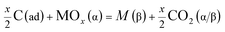
xCH4(α/β) + MOx(α) = M(β) + xCO(α/β) + 2xH2(α/β)
| (1) |
Eqn (1) shows the total reaction, in which the metal elements involved in the reaction are represented by M; the metal oxides and product phase are represented by α and β, respectively. A series of sub-steps are involved in the chemical reaction process.
(a) Cracking of chemisorbed methane;18
| | |
CH4(ad) = CH3(ad) + H(ad)
| (1a) |
| | |
CH3(ad) = CH2(ad) + H(ad)
| (1b) |
| | |
CH2(ad) = CH(ad) + H(ad)
| (1c) |
| | |
CH(ad) = C(ad) + H(ad)
| (1d) |
| | |
C(ad) = C(dissolved)
| (1e) |
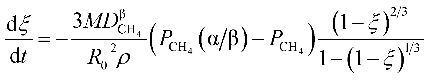
If C(ad) cannot be consumed completely, the reaction interface or blocked pores would be covered by the dissolved carbon, which is formed through eqn (1e), and retard further reduction.
(b) Reduction of metal oxides by H(ad) and C(ad);
| | |
2xH(ad) + MOx(α) = M(β) + xH2O(α/β)
| (1f) |
| |
 | (1g) |
or
| | |
xC(ad) + MOx(α) = M(β) + xCO(α/β)
| (1h) |
(c) The water-gas-shift and Boudouard reactions at the interface;
| | |
C + H2O(α/β) = CO(α/β) + H2(α/β)
| (1i) |
| | |
C + CO2(α/β) = 2CO(α/β)
| (1j) |
(vi) Chemical desorption of gaseous products (CO, H2).
(vii) Physical desorption of gaseous products (CO, H2).
(viii) Internal diffusion of gaseous products (CO, H2).
(ix) External diffusion of gaseous products (CO, H2).
In general, the internal diffusion of gas or interfacial chemical reaction is the restrictive step,19 which mainly depends on the properties of reaction systems. For example, the restrictive step can change if the particle size increases. Due to the similarity of formulae between the steps (ii) and (viii), this work only chooses step (ii) (internal diffusion of CH4) as a typical example to display the derivation process and the derivation process of step (viii) is shown in the ESI.† In addition, only a brief derivation process is shown in the body of the article and the ESI† shows the detailed derivation process in the corresponding section.
3. The theoretical analysis of single reaction
3.1. Interface chemical reaction
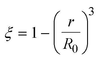
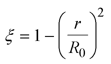
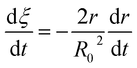
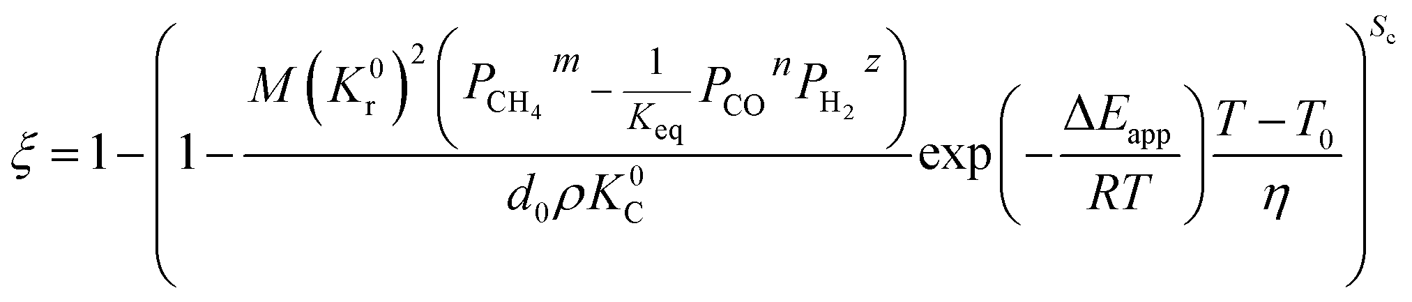
3.1.1. Spherical particles. Metal oxides with a spherical shape are shown in Fig. 1, in which x represents the thickness of the reaction product and R0 and r represent the radii of the initial particle and unreacted metal oxides, respectively. Due to the non-porosity of the initial particle and the invariance of the overall particle shape proposed in the previous section, CH4 reduction should obey the unreacted shrinking core mechanism,20,21 where the unreacted shrinking core model is commonly used in non-catalytic gas–solid reactions of metallurgy and chemical engineering.21 Although the unreacted shrinking core model cannot cover all the mechanisms of gas–solid reactions, it is widely accepted as the best simple model for most of the principal gas–solid reactions.22–24 In addition, our previous research also proved the presence of unreacted shrinking core for titania reduction.6,7,25,26 The ξ (reduction extent) at r can be expressed by using the following eqn (2):| |
 | (2) |
 |
| | Fig. 1 Spherical particle during the reduction process with CH4. | |
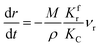
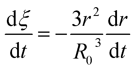
Eqn (3) can be obtained by the differentiation of eqn (2) with respect to time t.
| |
 | (3) |
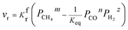
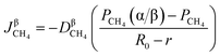
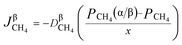
Rates of reaction per unit area on both sides of the reversible reaction27–30 in eqn (1) can be calculated as follows:
| | |
vbr = KbrPCOn(α/β)PH2z(α/β)
| (5) |
Here, reaction rate coefficients are defined by using
Kfr and
Kbr, and
m,
n and
z are the reaction orders. For
eqn (1), the overall reaction rate can be calculated per unit area by using
| | |
vr = vfr − vbr = KfrPCH4m(α/β) − KbrPCOn(α/β)PH2z(α/β)
| (6) |
When the interfacial chemical reaction is the control part of the reduction process, the resistance in diffusion (product layer and other steps) can be neglected, thus
The equilibrium constant of reaction (1) can be calculated as
Substituting eqn (10) in eqn (6), eqn (11) is obtained as:
| |
 | (11) |
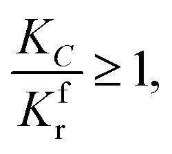
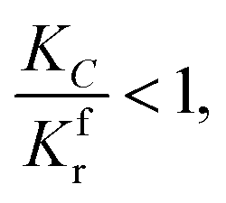
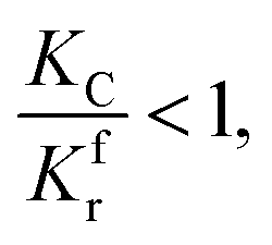
Because of the direct correlation between methane cracking and the reaction rate, two conditions are proposed: if the cracking is too fast, the deposited carbon coating on the surface of particles will retard the reaction, as discussed above; if the cracking rate is too small, the reduction will still be retarded because of the slow consumption of CO2 and H2O. Thus, there are two cases:
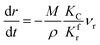
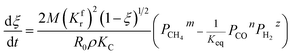
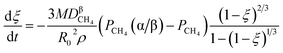
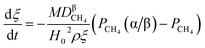
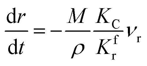
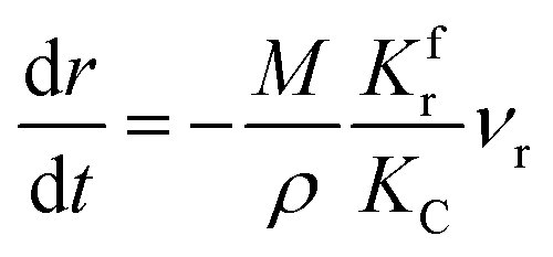
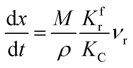
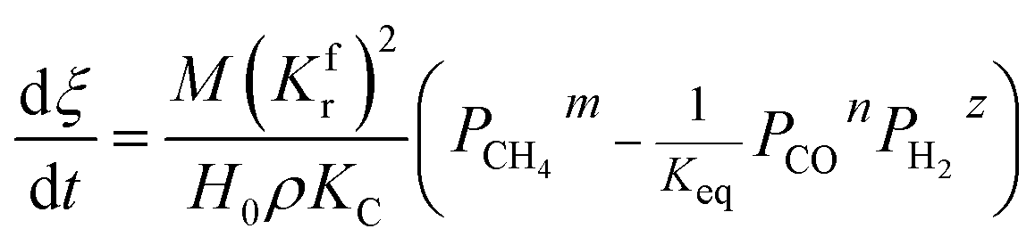
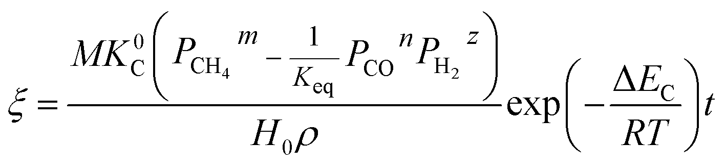
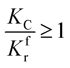
(1) When  (Kc is the cracking rate coefficient of methane), the growth rate of α in the radial direction, which is proportional to the overall reaction rate, can be expressed as follows:
| |
 | (12) |
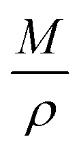
where
M represents the molecular weight of metal oxides and
ρ is the density. Thus, the reduction between the cracked products and metal oxides is the rate limiting step and the radial growth rate of α would be positively correlated with the reaction rate in this case. Due to the hindrance of excess deposited carbon, the radial growth rate of α would be negatively correlated with methane cracking. Therefore,
KC (the cracking rate coefficient of methane) and
Kfr (the reaction rate coefficient) are in the denominator and numerator, respectively. In addition,

was obtained through the derivation of dimensions.
Eqn (3) combines with
eqn (11) and
(12) to give the following equation.
| |
 | (13) |
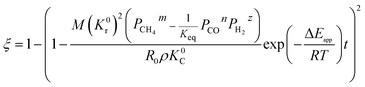
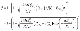
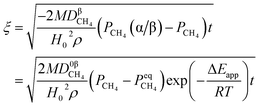
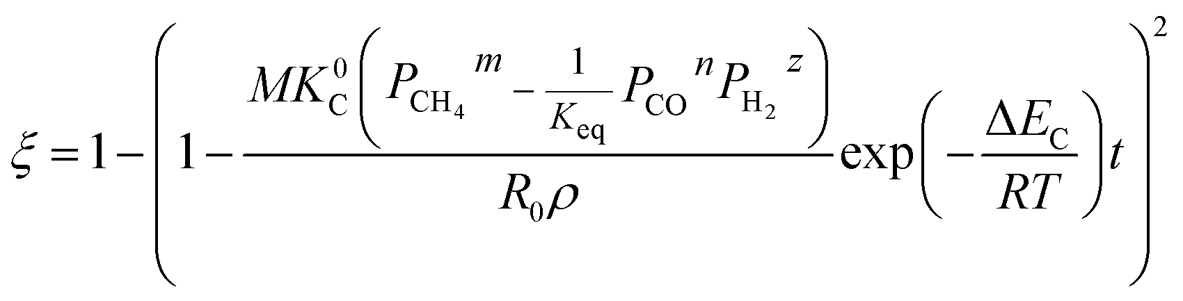
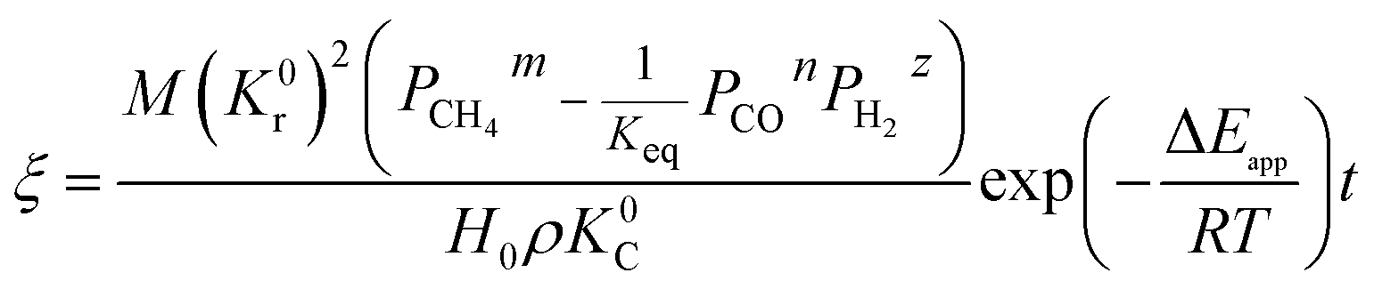
By integrating eqn (13) with the initial condition of ξ = 0 when t = 0, eqn (14) can be obtained.
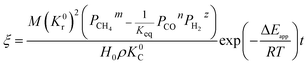
| |
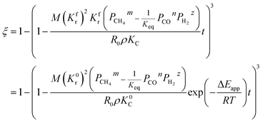 | (14) |
where Δ
Eapp = 2Δ
Er − Δ
Ec,
K0r and
K0C are temperature independent constants; is the apparent activation energy; Δ
Er and Δ
Ec are the activation energies of the reduction reaction and methane cracking, respectively.
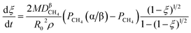
(2) When 
| |
 | (15) |
The process of methane cracking is the rate limiting step and the radial growth rate of α would be positively correlated with the cracking rate. In this case, it makes sense to put KC (the cracking rate coefficient of methane) in the numerator of the formula. Similarly, the relation between ξ and t can be expressed in eqn (16).
| |
 | (16) |
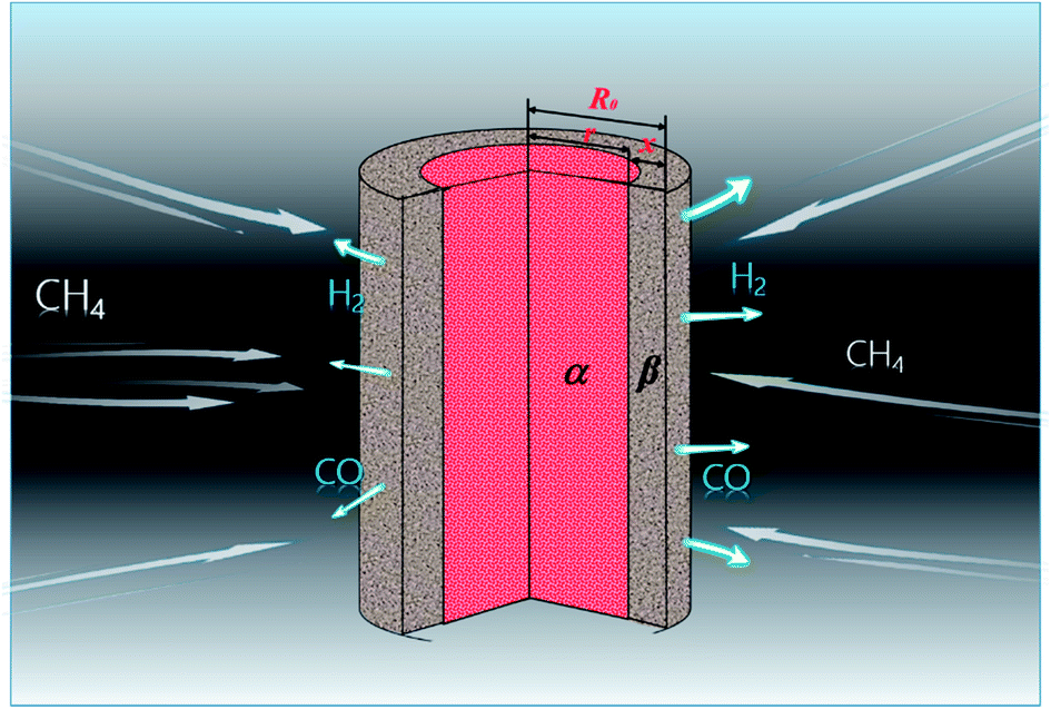
3.1.2. Cylindrical particles. The metal oxides with a cylindrical shape are shown in Fig. 2, in which x is the thickness of the reaction product, R0 and r are the radii of the cylindrical particle and unreacted metal oxides, respectively. The reduction on both top and bottom surfaces is negligible when the height of the cylindrical particle is far more than its diameter. Hence, ξ can be calculated by| |
 | (17) |
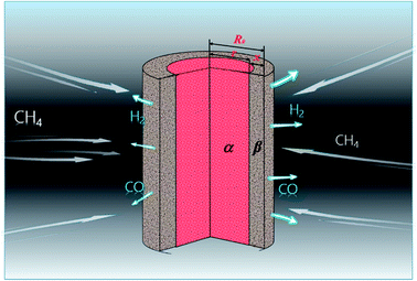 |
| | Fig. 2 Cylindrical particle during the reduction process with CH4. | |
By the differentiation of eqn (17) with respect to time t, eqn (18) is obtained as:
| |
 | (18) |
(1) When 
| |
 | (19) |
Eqn (20) can be deduced by combining eqn (11), (17), (18) and (19) as follows:
| |
 | (20) |
By substituting the initial conditions (ξ = 0, t = 0) in the equation mentioned above, eqn (21) can be derived after rearrangement
| |
 | (21) |
where Δ
Eapp = 2Δ
Er − Δ
Ec.
(2) When 
| |
 | (22) |
Similarly, the relation between ξ and t can be derived as shown in eqn (23).
| |
 | (23) |
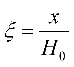
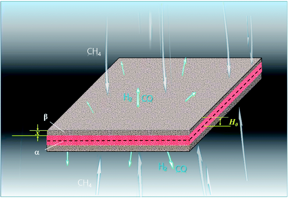
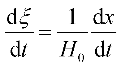
3.1.3. Lamellar particles. The metal oxides with lamellar-shaped particles are shown in Fig. 3, where H0 is the half-height of the lamellar particle. ξ can be calculated by:| |
 | (24) |
 |
| | Fig. 3 Lamellar particle during the reduction process with CH4. | |
It can be derived by differentiating eqn (24) with respect to time t.
| |
 | (25) |
(1) When 
| |
 | (26) |
Then, combining eqn (11), (24), (25) and (26), eqn (27) can be obtained.
| |
 | (27) |
By substituting the initial conditions (ξ = 0, t = 0) in the above equation, eqn (28) can be obtained.
| |
 | (28) |
where Δ
Eapp = 2Δ
Er − Δ
Ec.
(2) When 
| |
 | (29) |
Similarly, the relation between the reaction and time can be expressed as shown in eqn (30).
| |
 | (30) |
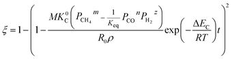
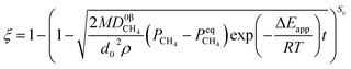
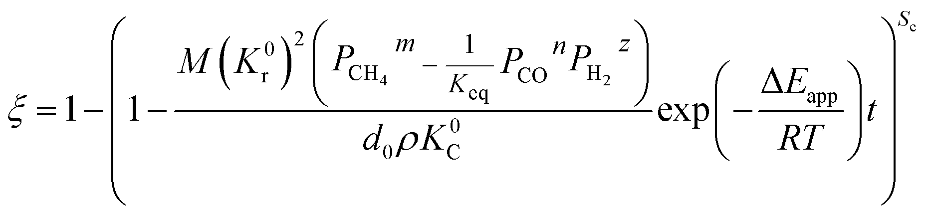
Two parameters are defined to unify the form of formulae: the shape coefficient Sc, which is equal to 3, 2 and 1 when the raw materials are spherical-shaped, cylindrical-shaped and lamellar-shaped, respectively; the equivalent diameter d0 represents the diameter of spherical particles, the diameter of cylindrical particles and the half height of lamellar particles, respectively. Under the isothermal condition, the derived formula can be rewritten as eqn (31).
When 
| |
 | (31) |
When 
| |
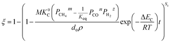 | (32) |
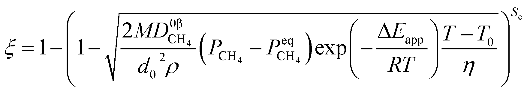
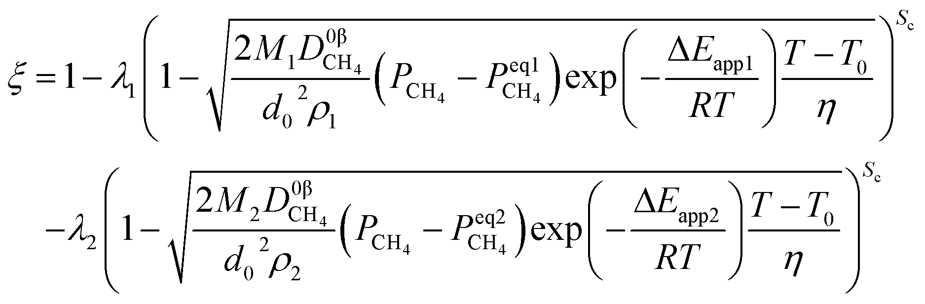
In industrial applications, most of the reduction processes of metal oxides are non-isothermal processes, such as the temperature of iron oxide in the shaft furnace increasing gradually due to furnace burden descent and the reverse flow of between gas and furnace burden. Furthermore, the coexistence of endothermic and exothermic reactions can also influence the temperature even in a single particle. Therefore, it is important to construct a model to predict the reduction process under non-isothermal conditions.
In this study, the rate of increase in the temperature η is assumed to be a constant value. The relationship between temperature (T) and time (t) can be calculated by,
in which
T0 represents the initial temperature. Here, we only discussed the simplest non-isothermal process (linear relationship). If the relationship between temperature and time is determined, any other non-isothermal formula can also be determined with the help of
eqn (31) and
(32). This non-isothermal model can be applied to the reactions involving powders and small pellets when they occur at moderate temperatures. Furthermore, reactions involving large pellets can also be predicted by this model when heat transfer is not the limiting factor of the reaction.
By substituting eqn (33) into eqn (31) and (32), the equations become.
When 
| |
 | (34) |
When 
| |
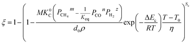 | (35) |
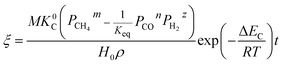
3.2. Diffusion in the product layer
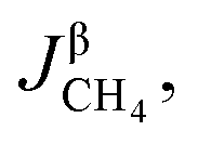
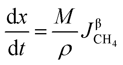
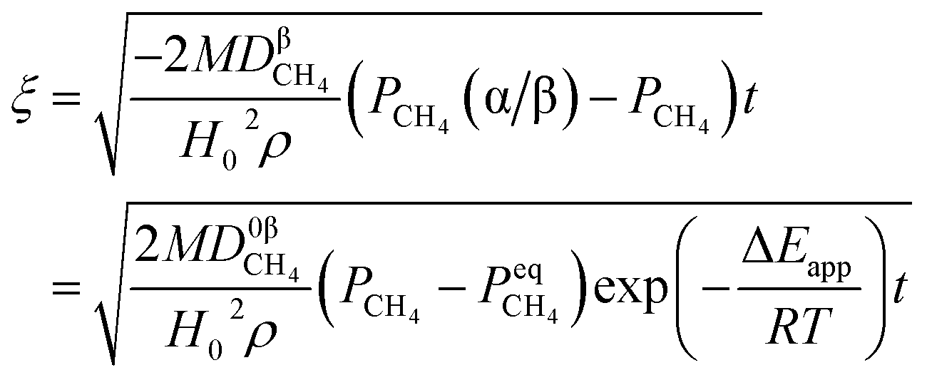
3.2.1. Spherical particles. When the gas diffusion in the product layer is the control link of the whole reaction, the growth rate of α in the radial direction, which is in direct proportion to the CH4 flux,  is given as:
| |
 | (36) |
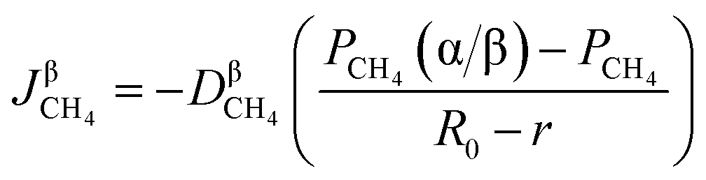
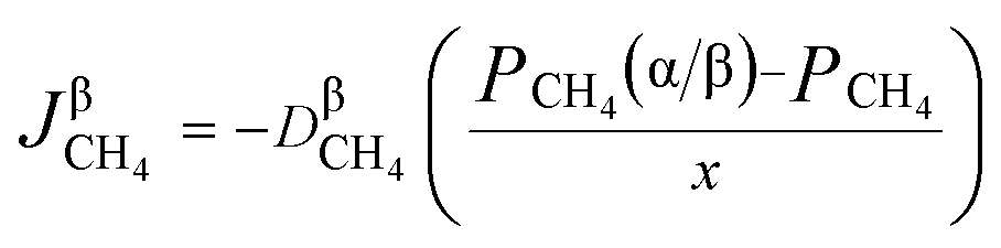
According to the Fick's first law of diffusion, CH4 flux is expressed as
| |
 | (37) |
where

represents the diffusion coefficient of CH
4 in the β phase;
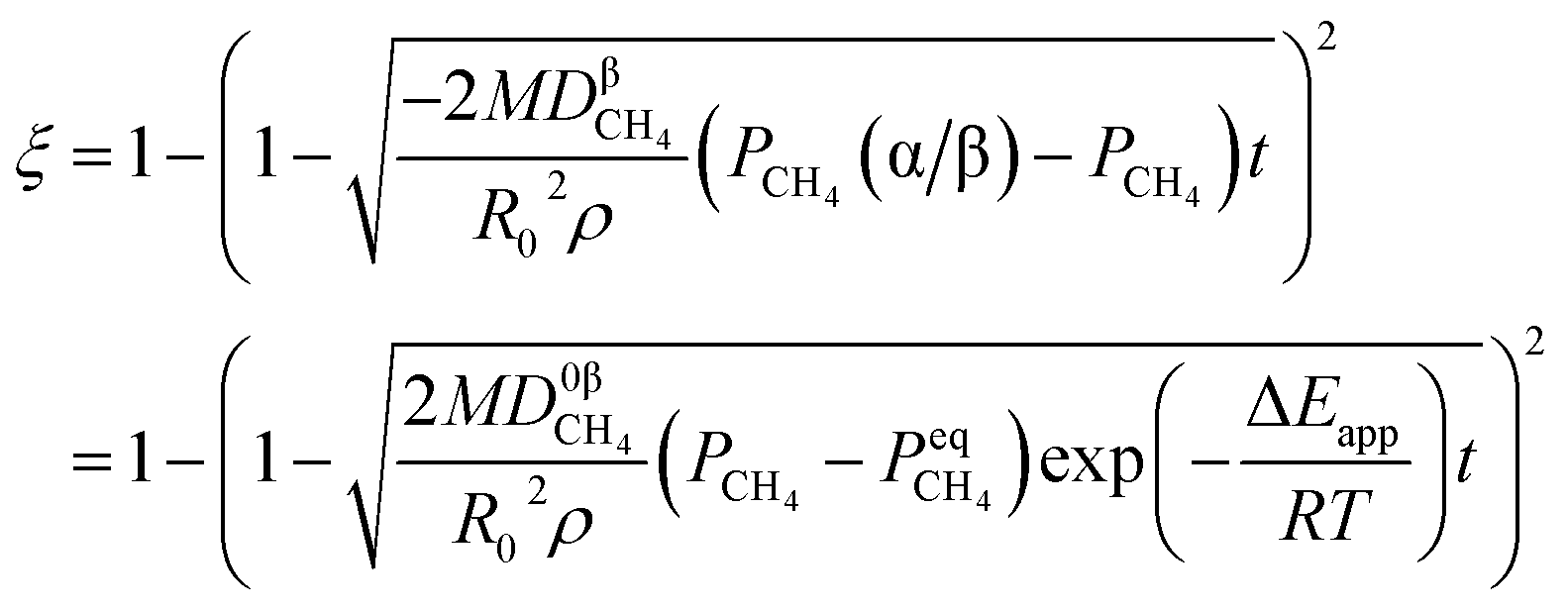
Eqn (38) is given by integrating eqn (2), (3), (36) and (37).
| |
 | (38) |
Eqn (38) is integrated and rearranged to obtain eqn (39).
| |
 | (39) |
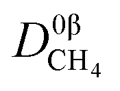
where

represents a constant that's not affected by temperature,

is the amount of CH
4 in equilibrium and Δ
Eapp is the apparent activation energy.
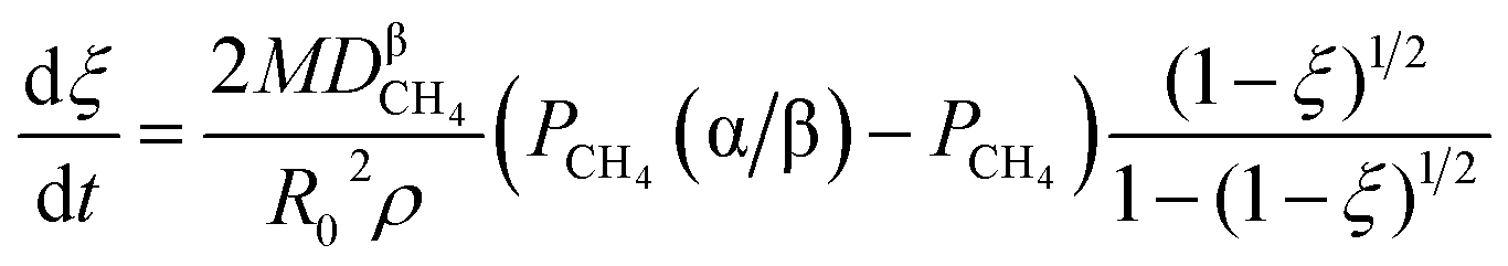
3.2.2. Cylindrical particles. Similarly, the growth rate of α in the radial direction should obey eqn (36). Combining eqn (17), (18), (36) and (37), eqn (40) can be obtained.| |
 | (40) |
Eqn (40) can be integrated and rearranged as
| |
 | (41) |
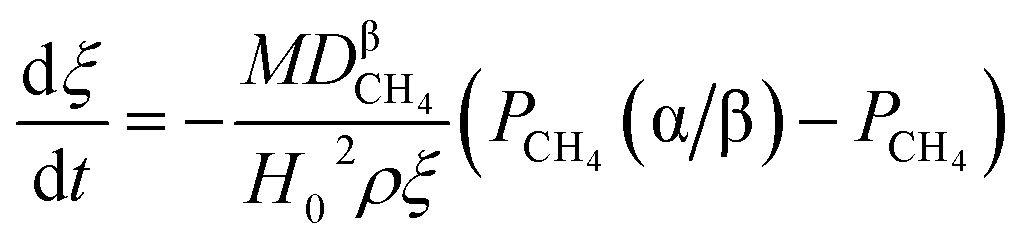
3.2.3. Lamellar particles. The growth rate of the thickness of the product layer is proportional to 
| |
 | (42) |
According to the Fick's first law of diffusion, eqn (43) can be given as
| |
 | (43) |
By combining eqn (24), (25), (42) and (43), eqn (44) can be obtained.
| |
 | (44) |
Integrating and rearranging eqn (44) yields eqn (45).
| |
 | (45) |
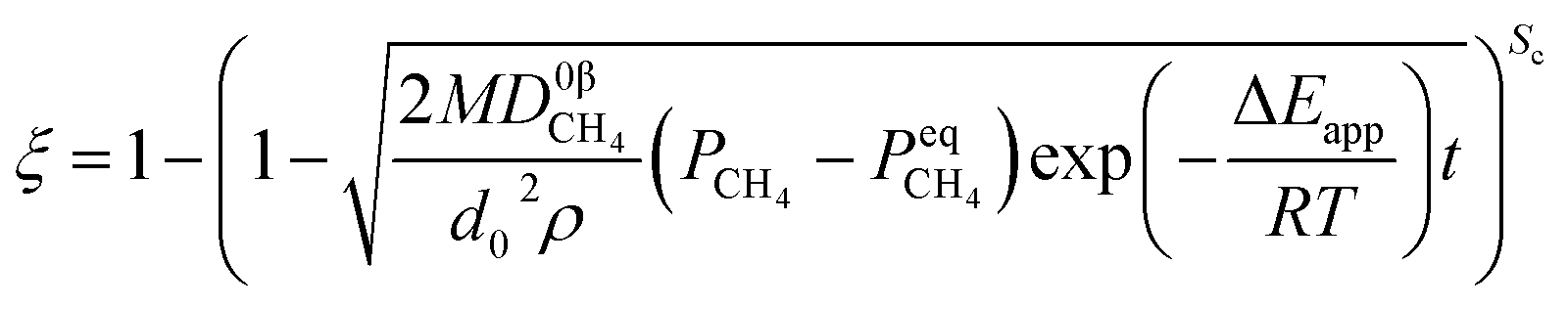
If the shape coefficient Sc and the equivalent diameter d0 are introduced into the model, the kinetic equation can be rewritten as
| |
 | (46) |
For spherical-shaped particles, Sc is equal to 3, 2 and 1 when the raw materials are spherical-shaped, cylindrical-shaped and lamellar-shaped, respectively; d0 represents the diameter of spherical particles, the diameter of cylindrical particles and the half-height of lamellar particles, respectively.
For non-isothermal reduction,
| |
 | (47) |
4. The theoretical analysis of dual reactions
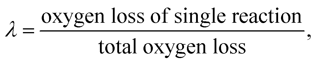
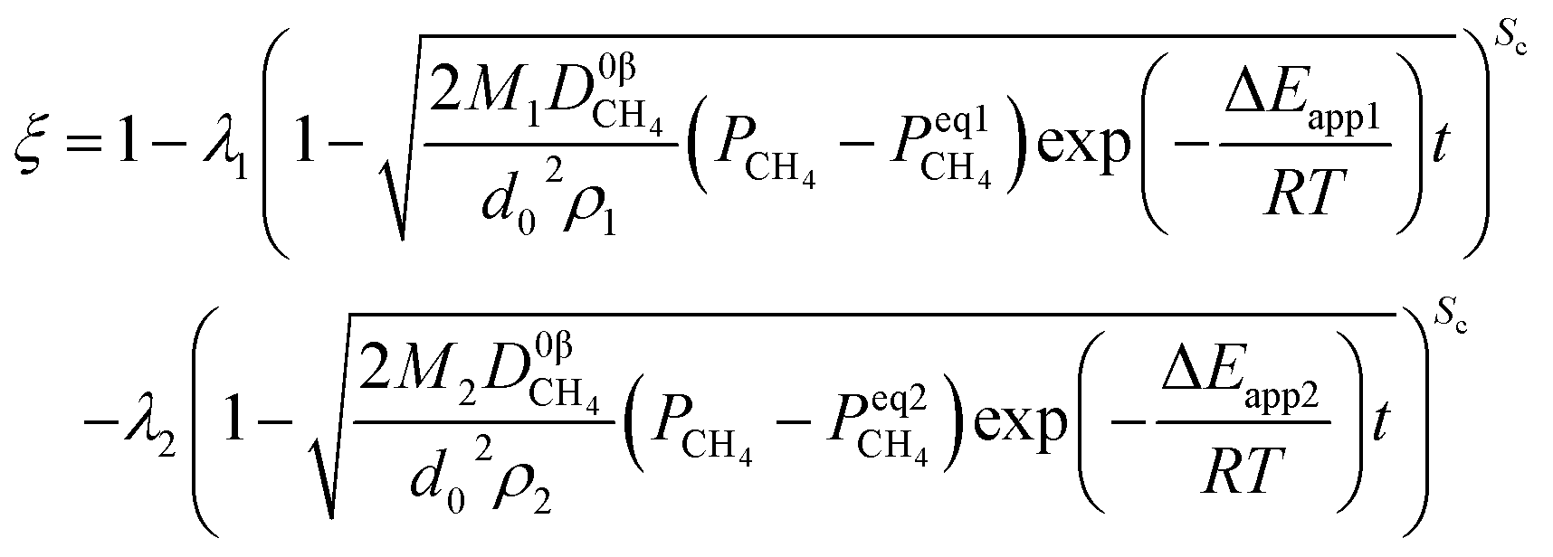
Developing a model to describe the reactions of dual interfaces or multiple interfaces is imperative and necessary. For example, when multiple valencies exist simultaneously in the reduction of metal oxides by CH4, the reaction process described by one interface model is inaccurate and even incorrect. When two reactions occur synchronously, the reactant in the second reaction is the product obtained in the first reaction. Two cases can be given:
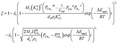
(1) When the rate of product formation of the first reaction is much larger than its consumption in the second reaction, there will be two coexisting reaction interfaces in the particle. ξ can be calculated as
where
λ1 and
λ2 are the coefficients determined by the loss of oxygen in each single reaction. According to
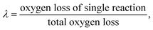
the value of
λ can be obtained and the order of reaction is represented by 1 or 2. The overall reduction extent is calculated by adding
ξ1 and
ξ2 with corresponding weights;
ξ1 and
ξ2 represent the reduction extent in each single reaction.
(2) There is only one interface when the rate of product formation of the first reaction is much less than its consumption in the second reaction, and the kinetic model, in this case, should be exactly the same as that of a single reaction.
For simplicity, the condition  is taken as an example to deduce the formulae.
4.1. Interface chemical reaction
When a chemical reaction is a controlling step in the dual reactions, integrating eqn (31) and (48) yield eqn (49) and (50).| |
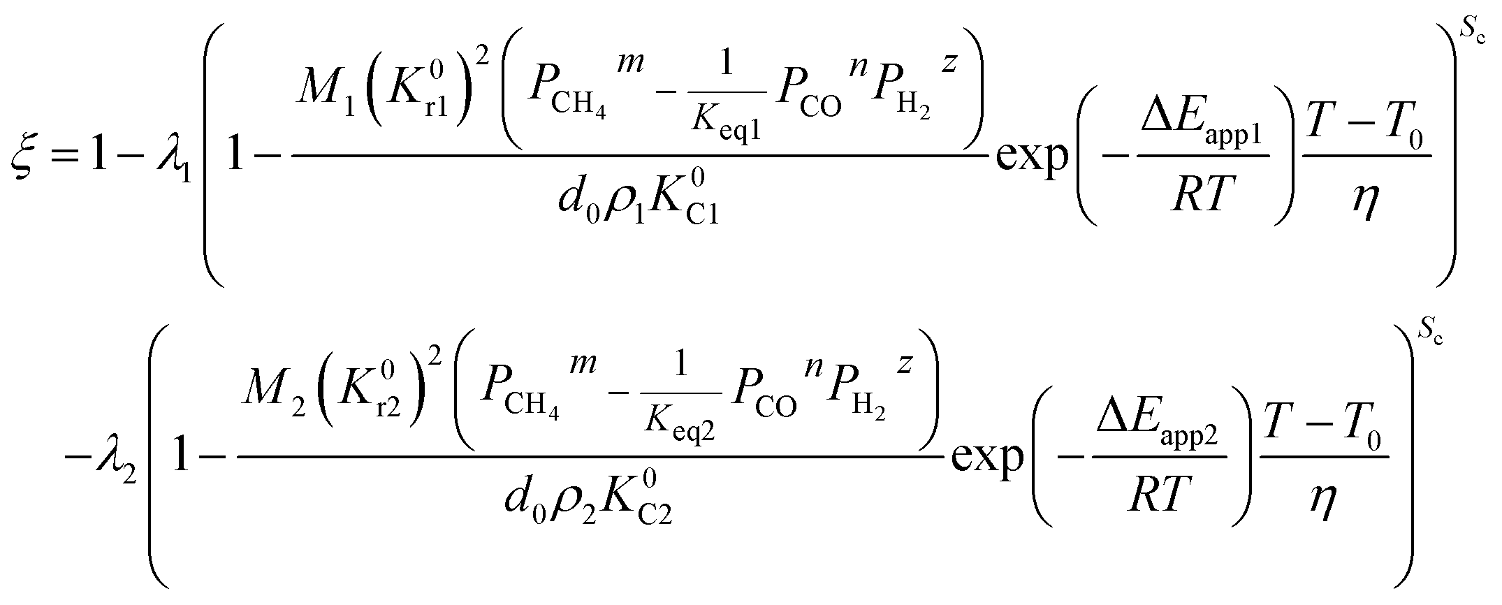
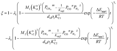 | (49) |
Under the non-isothermal condition,
| |
 | (50) |
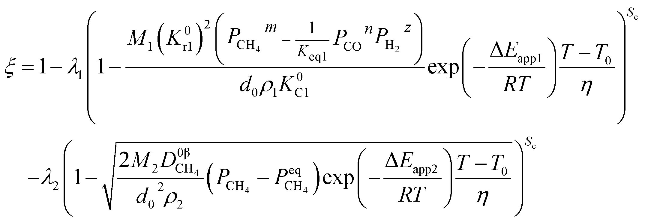
4.2. Mixed control
When one step of chemical reaction controls a reaction and CH4 diffusion in the product layer controls another reaction, the theoretical analysis of ξ can be done by integrating eqn (31), (46) and (48).| |
 | (51) |
For the non-isothermal reduction reaction,
| |
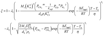 | (52) |
4.3. Diffusion in the product layer
If diffusion controls all reactions, it gives| |
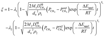 | (53) |
Likewise, under the non-isothermal condition, the equation can be obtained as
| |
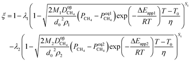 | (54) |
5. Practical application of the mathematical model
To get a simpler model, heat transfer is not discussed in this work, only the processes of chemical reaction and mass transfer are considered. Thus, it can be applied to the reduction of powder and pellets with small size or in systems, such as large pellets, where heat transfer is not the controlling factor. Generally, the nucleation and growth mechanism play a dominant role when the temperature is lower and the reduction at high temperatures may obey solid-state ion diffusion because of sintering. Hence, the developed model will be appropriate when the reaction occurrs at moderate temperatures.
5.1. Nickel oxide reduction predicted by the developed model
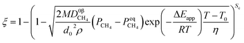
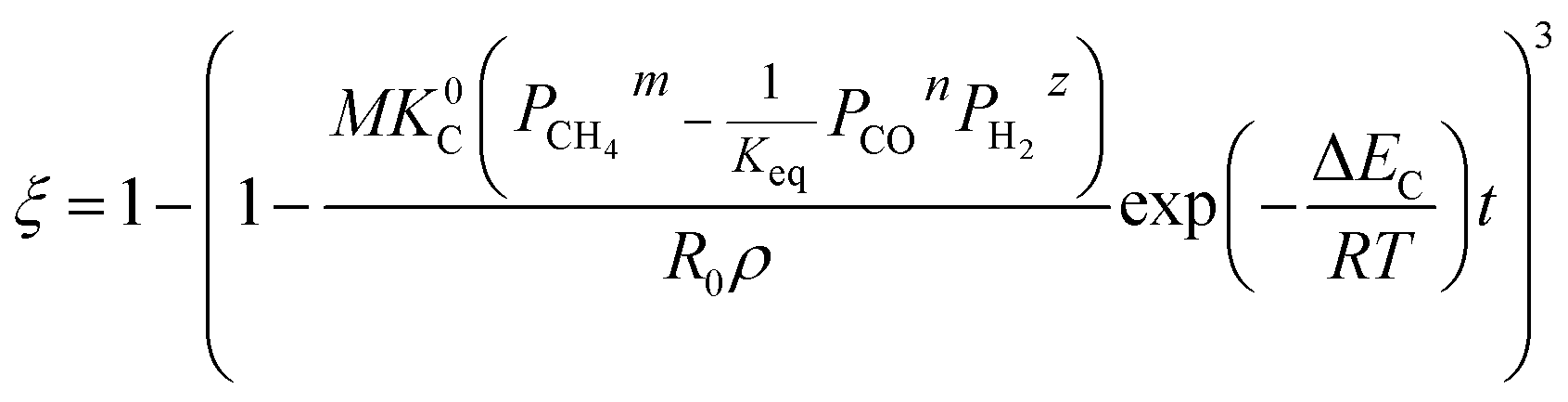
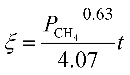
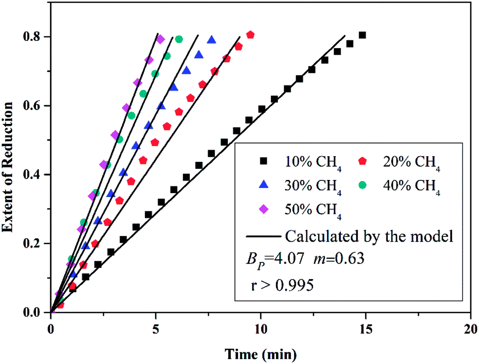
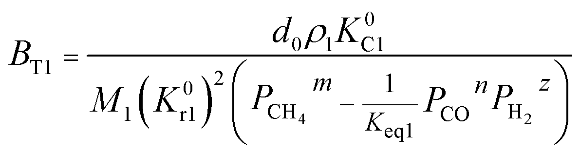
The application of the model will be very convenient because a lot of parameters are included in the derived model, such as T, R, and ρ. Rashidi et al.2 have done experimental research on the methane reduction of nickel oxide based on thermogravimetry with a methane concentration of 10–50% (with a gas flow rate of 200 mL L−1). A cylindrical sample with a diameter of 7 mm and 0.6 mm thickness was used in the experiment. Because the diameter is much larger than the thickness, the sample can be considered as lamellar-shaped. In general, the methane cracking rate can be very fast when the temperature is over 1000 °C. Therefore, eqn (30) and (45) can work in this case and a better prediction is found by using eqn (30). When methane concentration as a single factor is studied, a parameter, 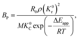 is defined as convenient to describe experimental data. BP is a function of R0, ρ, and M and it is affected by the substance. Once the metal oxides are fixed, BP becomes constant. The formula can be rewritten as,
| |
 | (55) |
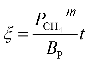
If the gas flow rate and Keq are large enough, then the formula becomes,
| |
 | (56) |
Then, Fig. 4 shows the predicted curves calculated by eqn (56), in which solid lines are the values calculated by the model and the dotted lines represent experimental data. It should be noted that a thick layer of nickel will be formed around the particle (at the final stage of the reaction) and the diffusion and movement of the gases will be hindered. Therefore, the data for reduction extents less than 0.8 are considered during the fitting. By comparing the curves, it can be observed that the developed model can describe the reduction very well and the obtained kinetic equation is given as eqn (57).
| |
 | (57) |
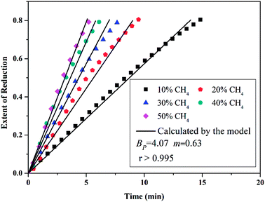 |
| | Fig. 4 Conversion extent vs. time curves for different CH4 concentrations at 660 °C (933 K). | |
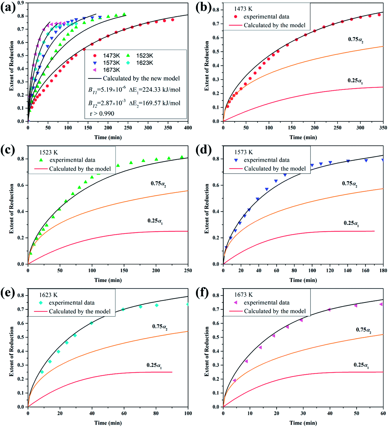
5.2. Titania reduction predicted by the developed model
The reduction of titania by CH4-containing gas (5 vol pct CH4–75 vol pct H2) under the isothermal condition was investigated by Zhang et al.5 In the experiment, titania powders (in the range of 212 to 355 μm or 355 to 500 μm) were used as the raw materials. Fig. 5(a) shows that the dotted lines represent experimental data. It can be found that the reduction path is TiO2 → Ti5O9 → Ti4O7 → Ti3O5 → Ti2O3 → (TiO–TiC)ss1,5 and the complex process can be described by reactions (58a–e).| | |
5TiO2 + CH4 → Ti5O9 + CO + 2H2
| (58a) |
| | |
4Ti5O9 + CH4 → 5Ti4O7 + CO + 2H2
| (58b) |
| | |
3Ti4O7 + CH4 → 4Ti3O5 + CO + 2H2
| (58c) |
| | |
2Ti3O5 + CH4 → 3Ti2O3 + CO + 2H2
| (58d) |
| | |
½Ti2O3 + (½ + 2x)CH4 → xTiCss + (1 − x)TiOss + (½ + x)CO + (1 + 4x)H2
| (58e) |
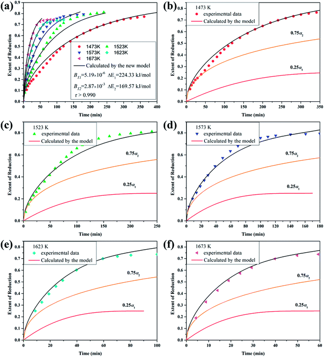 |
| | Fig. 5 (a) Theoretical and experimental curves: titania reduced by 5 vol pct CH4–75 vol pct H2 gas mixture at different temperatures; (b)–(f) kinetic curves (reduction extent vs. time) of the step reactions and overall reaction corresponding to (a). | |
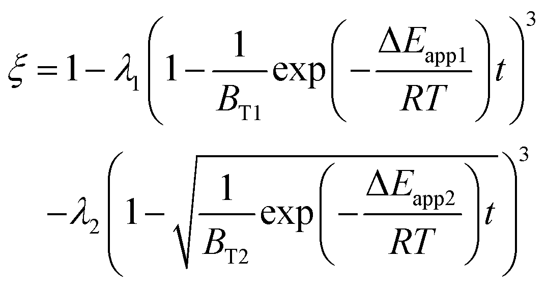
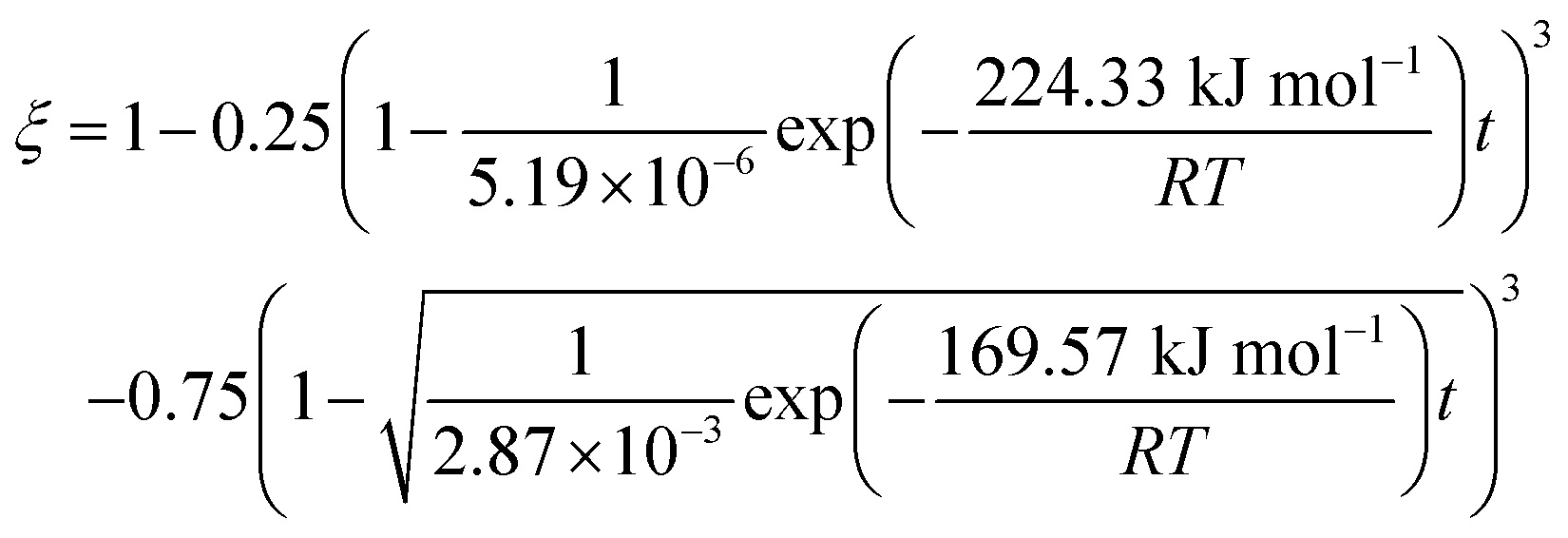
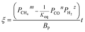
Therefore, the reaction from TiO2 to Ti2O3 can be considered as the first reaction and Ti2O3 to (TiO–TiC)ss can be regarded as the second reaction. The dual reactions have been verified to coexist in the reduction (TiC and Ti2O3 were confirmed to be formed in one sample5). Thus, the derived dual reaction model can be applied for the prediction of experimental data. λ1 and λ2 have values of 0.25 and 0.75, respectively. Different dual reaction formulae are employed to model the reduction kinetics and it is found that eqn (51) gives the best fitting results. To simplify the model, two parameters are defined, 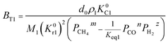 and
and 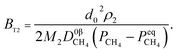 Compared with the values of PCH4, other values (PCO, PH2 and
  ) are very small and can be neglected, so BT1 and BT2 can be regarded as constants. Then, eqn (51) can be rewritten as
| |
 | (59) |
The results predicted by the dual reaction model are shown as solid lines in Fig. 5(a) and the obtained kinetic formula is shown as eqn (60).
| |
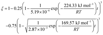 | (60) |
Furthermore, based on the new model, the reduction kinetics for TiO2 to Ti2O3 and Ti2O3 to (TiO–TiC)ss are obtained successfully as shown in Fig. 5(b)–(f).
5.3. Comparison of the application of different models
Table S1† shows the earlier reported kinetic models,11,31,32 which are compared with the new model developed in this work with practical applications. The reduction reaction of titania by 5 vol pct CH4–75 vol pct H2 gas mixture at 1473 K (investigated by Zhang et al.5) was selected to be the example calculated by different models. Obviously, the results obtained by the newly developed model are better than those obtained by the previous models, as shown in Table S1 and Fig. S1.† This is because the newly developed model considers the dual reactions, which occur simultaneously and is more close to practice.
5.4. The limitation of this model
This work assumed that all metal oxides are nonporous and these particles have a uniform diameter that remains constant during reduction. The model, developed in this work, only considers the effect of mass transfer and chemical reaction but not heat transfer. Therefore, the reactions involving powders and small pellets can be applied to this mathematical model when the reaction occurs at moderate temperatures. Furthermore, reactions involving large pellets can also be predicted by this model when the heat transfer is not the limiting factor of the reaction. However, the mixed controlling mechanism (the resistance of both chemical reaction and diffusion is large) for a single reaction is not considered in this study, which will be done in our future work.
6. Conclusions
(1) In this work, the reduction mechanism between metal oxides and methane was discussed in detail and a new mathematical model, which was in the form of explicit functions of many parameters, for methane reduction was developed. Particularly, the comparison of methane cracking rate and reaction rate was involved in the model.
(2) Both the gas diffusion in the product layer and chemical reaction controlled mechanisms were considered during the derivation. The kinetic formulae for the reduction of three shapes (spherical, cylindrical and lamellar) of particles were deduced as well and by incorporating two parameters Sc and d0, these formulae were unified to one formula.
(3) Whether it is an isothermal or non-isothermal condition, the model can be used to simulate the reduction between methane and metal oxides. Furthermore, it can describe the reduction of varied-valence metal oxides.
(4) The experimental data obtained from literature could be feasibly predicted using the new model of methane reduction.
Conflicts of interest
There are no conflicts to declare.
Acknowledgements
This work is supported by the National Natural Science Foundation of China (51674053, 51604046), National Key R&D Program of China (2018YFC1900500), Fok Ying Tung Education Foundation (171111), joint fund between Shenyang National Laboratory for Materials Science and State Key Laboratory of Advanced Processing and Recycling of Nonferrous Metals (18LHPY015), Young Elite Scientists Sponsorship Program by CAST (2018QNRC001) and the Venture & Innovation Support Program for Chongqing Overseas Returnees (cx2019041, cx2018055).
Notes and references
- O. Ostrovski and G. Zhang, AIChE J., 2006, 52, 300–310 CrossRef CAS.
- H. Rashidi, H. A. Ebrahim and B. Dabir, Thermochim. Acta, 2013, 561, 41–48 CrossRef CAS.
- Y. He and P. C. Pistorius, Metall. Mater. Trans. B, 2016, 47, 1538–1541 CrossRef CAS.
- W. Park and S. M. Jung, ISIJ Int., 2015, 55, 166–174 CrossRef CAS.
- G. Zhang and O. Ostrovski, Metall. Mater. Trans. B, 2000, 31, 129–139 CrossRef.
- J. Dang, F. Fatollahi-Fard, P. C. Pistorius and K. C. Chou, Metall. Mater. Trans. B, 2018, 49, 123–131 CrossRef CAS.
- J. Dang, F. Fatollahi-Fard, P. C. Pistorius and K. C. Chou, Metall. Mater. Trans. B, 2017, 48, 2440–2446 CrossRef CAS.
- H. A. Ebrahim and E. Jamshidi, Miner. Process. Extr. Metall., 2009, 118, 194–200 CrossRef CAS.
- H. M. Ahmed and S. Seetharaman, Metall. Mater. Trans. B, 2010, 41, 173–181 CrossRef.
- S. Shirchi, B. Khoshandam and F. Hormozi, J. Taiwan Inst. Chem. Eng., 2015, 51, 171–176 CrossRef CAS.
- W. Jander, Z. Anorg. Allg. Chem., 1927, 163, 1–30 CrossRef CAS.
- R. E. Carter, J. Chem. Phys., 2010, 34, 2010–2015 CrossRef.
- M. Avrami, J. Chem. Phys., 1941, 9, 177–184 CrossRef CAS.
- M. Avrami, J. Chem. Phys., 1939, 7, 1103–1112 CrossRef CAS.
- A. M. Ginstling and B. I. Brounshtein, Russ. J. Appl. Chem., 1950, 23, 1327–1338 CAS.
- K. C. Chou, ISIJ Int., 2018, 58, 785–791 CrossRef CAS.
- J. Dang and K. C. Chou, ISIJ Int., 2018, 58, 585–593 CrossRef CAS.
- N. Anacleto and O. Ostrovski, Metall. Mater. Trans. B, 2004, 35, 609–615 CrossRef.
- K. C. Chou, J. Am. Ceram. Soc., 2006, 89, 1568–1576 CrossRef CAS.
- G. Zhang and O. Ostrovski, Metall. Mater. Trans. B, 2001, 32, 465–473 CrossRef.
- J. Szekely, J. W. Evans and H. Y. Sohn, Gas-Solid Reactions, Academic Press, New York, 1976 Search PubMed.
- S. Homma, S. Ogata, J. Koga and S. Matsumoto, Chem. Eng. Sci., 2005, 60, 4971–4980 CrossRef CAS.
- M. Ishida and C. Y. Wen, Chem. Eng. Sci., 1971, 26, 1031–1041 CrossRef CAS.
- M. Ishida, C. Y. Wen and T. Shirai, Chem. Eng. Sci., 1971, 26, 1043–1048 CrossRef CAS.
- R. Zhang, J. Dang, D. Liu, Z. Lv, G. Fan and L. Hu, Sci. Total Environ., 2019, 69, 1–13 CrossRef PubMed.
- R. Zhang, D. Liu, G. Fan, H. Sun and J. Dang, Int. J. Energy Res., 2019, 43, 4253–4263 CrossRef CAS.
- L. Maier, B. Schädel, K. H. Delgado, S. Tischer and O. Deutschmann, Top. Catal., 2011, 54, 845–858 CrossRef CAS.
- M. K. Nikoo and N. A. S. Amin, Fuel Process. Technol., 2011, 92, 678–691 CrossRef CAS.
- M. N. Pedernera, J. PiñA and D. O. Borio, Chem. Eng. J., 2007, 134, 138–144 CrossRef CAS.
- J. W. Snoeck, G. F. Froment and M. Fowles, J. Catal., 1997, 169, 250–262 CrossRef CAS.
- P. Pourghahramani and E. Forssberg, Thermochim. Acta, 2007, 454, 69–77 CrossRef CAS.
- J. Dang, G. H. Zhang, K. C. Chou, R. G. Reddy, Y. He and Y. Sun, Int. J. Refract. Met. Hard Mater., 2013, 41, 216–223 CrossRef CAS.
Footnote |
| † Electronic supplementary information (ESI) available. See DOI: 10.1039/c9ra09418k |
|
| This journal is © The Royal Society of Chemistry 2020 |
Click here to see how this site uses Cookies. View our privacy policy here. 
 Open Access Article
 This Open Access Article is licensed under a Creative Commons Attribution-Non Commercial 3.0 Unported Licence
 ab and
Jie Dang
ab and
Jie Dang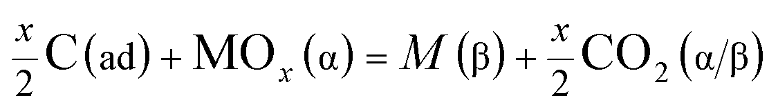


 (Kc is the cracking rate coefficient of methane), the growth rate of α in the radial direction, which is proportional to the overall reaction rate, can be expressed as follows:
 was obtained through the derivation of dimensions. Eqn (3) combines with eqn (11) and (12) to give the following equation.


 is given as:
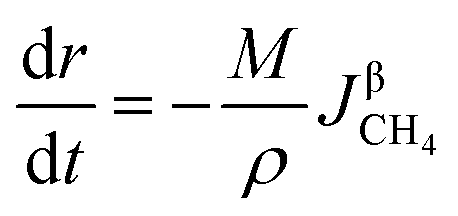
 represents the diffusion coefficient of CH4 in the β phase;

 represents a constant that's not affected by temperature,
  is the amount of CH4 in equilibrium and ΔEapp is the apparent activation energy.
 the value of λ can be obtained and the order of reaction is represented by 1 or 2. The overall reduction extent is calculated by adding ξ1 and ξ2 with corresponding weights; ξ1 and ξ2 represent the reduction extent in each single reaction.
 is taken as an example to deduce the formulae.
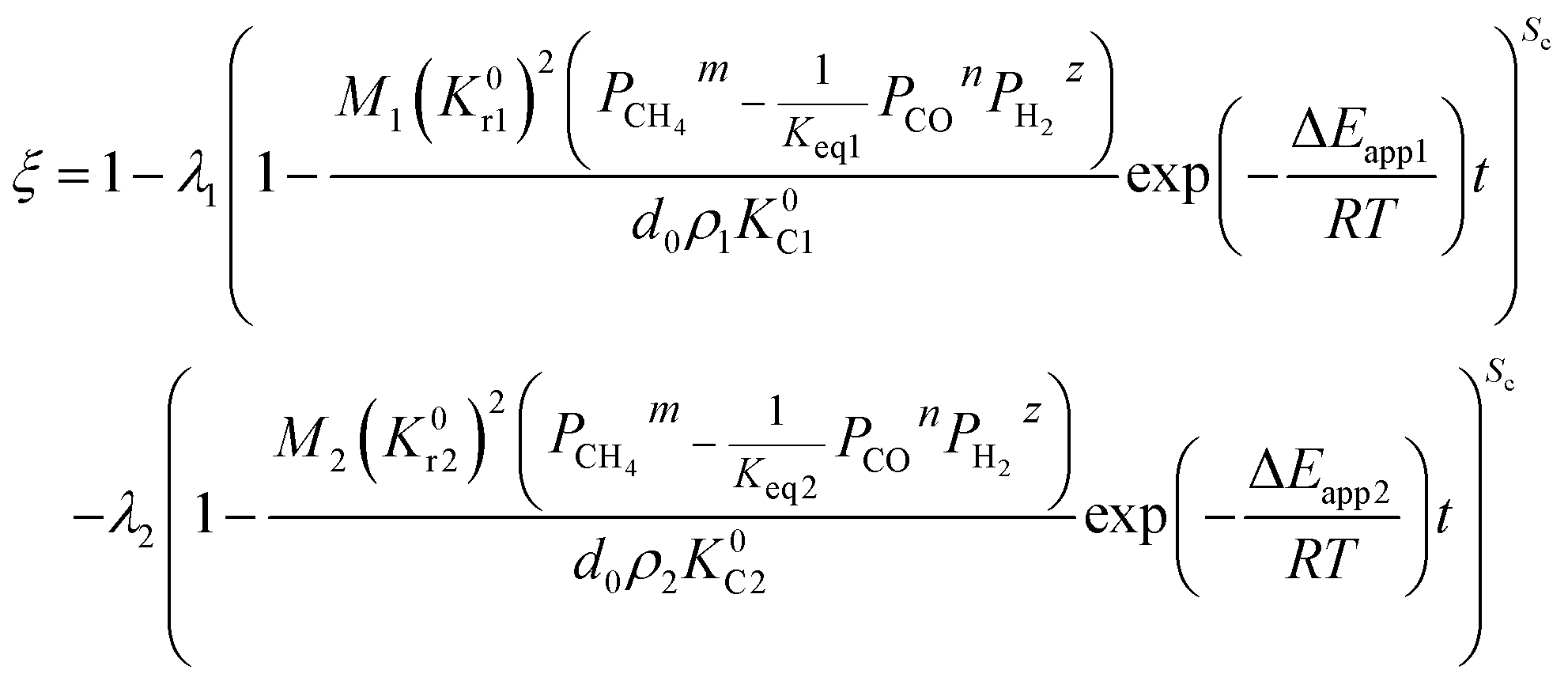

 is defined as convenient to describe experimental data. BP is a function of R0, ρ, and M and it is affected by the substance. Once the metal oxides are fixed, BP becomes constant. The formula can be rewritten as,
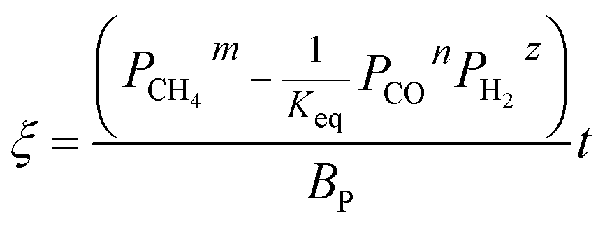
 and
and 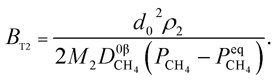 Compared with the values of PCH4, other values (PCO, PH2 and
  ) are very small and can be neglected, so BT1 and BT2 can be regarded as constants. Then, eqn (51) can be rewritten as