 Open Access Article
Asymmetric molecular modification of viologens for highly stable electrochromic devices†
Mark Kim,
Yong Min Kim and
Hong Chul Moon *
*
Department of Chemical Engineering, University of Seoul, Seoul 02504, Republic of Korea. E-mail: hcmoon@uos.ac.kr
First published on 2nd January 2020
Abstract
Viologens are one of the most well-known electrochromic (EC) chromophores. In particular, symmetric dialkyl viologens have been widely used in EC devices (ECDs), but suffer from the formation of viologen radical cation dimers that deteriorate device performance. In this work, we propose an effective route to suppress dimer formation through molecularly altering one of the N-substituents. We prepare 1-benzyl-1′-heptyl viologens and find that such asymmetric molecular structures attribute to the suppression of dimer production when used as EC chromophores. The suppression of dimer formation allows us to drive the device at relatively higher voltages, so that we could achieve viologen-based ECDs showing large transmittance changes between colored and bleached states, efficient and fast coloration, and stable coloration/bleaching cyclic operation. The results indicate that high-performance ECDs can be realized by utilizing viologens containing asymmetric molecular structures.
1. Introduction
Electrochemical displays have attracted great attention for use in transparent displays because of their simplicity in device configuration and fabrication process, low-voltage operation, and low-power consumption.1–15 An example of electrochemical displays is an electrochromic device (ECD) that changes its optical characteristics such as a color through redox reactions of electrochromic (EC) chromophores. The device performance strongly depends on the electrochemical and optical properties of its EC materials.Among EC materials including metal oxides,16,17 conducting polymers,18 metallo-supramolecular polymers,19 and small organic molecules,20,21 1,1′-disubstituted-4,4′-bipyridilium salts, referred to as viologens, have been extensively studied in ECDs.22,23 In particular, symmetric viologens bearing two identical alkyl N-substituents have been the most widely used and usually exhibit a blue-colored state.5,10,22,24 However, there are problems with the practical use of viologens. For example, dialkyl viologen radical cations tend to form dimers via spin-pairing when the length of the alkyl chains is sufficiently long (e.g., heptyl) and hydrophilic electrolytes are incorporated.25–28 The redox behaviors of dimers are quasi-reversible, resulting in relatively poor operational stability.25,29–31 studies on asymmetric viologens, which have two different N-substituents, have concentrated on the color tunability or pH-dependent redox behavior.32–34 Recently, we suggested the use of 1-heptyl-4-(4-pyridyl)pyridinium salt (monoheptyl viologen, MHV+) to decrease dimer production. The asymmetry of MHV+ suppressed the dimerization of colored species, and MHV+-based ECDs exhibited outstanding coloration/bleaching cyclic operation. The ECDs containing MHV+ displayed a magenta-colored state, but the coloration voltage was increased compared to disubstituted viologens displaying a blue-colored state.29
Herein, we extend the strategy of adjusting viologen symmetry to achieve highly stable high-performance ECDs. Previously, a few asymmetric viologens have been reported but the correlation between molecular symmetry and EC characterization of viologens has not been systematically investigated.35–37 To prepare asymmetric viologens, two different N-substituents of benzyl and heptyl groups were introduced into 4,4′-bipyridine, giving 1-benzyl-1′-heptyl-4,4′-bipyridinium salt (benzyl heptyl viologen, BHV2+). For a comparison, symmetric 1,1′-diheptyl-4,4′-bipyridinium salt (diheptyl viologens, DHV2+) were used in ECDs. In both systems, the other components contained in the EC layer were the same; 1-butyl-3-methylimidazolium tetrafluoroborate ([BMI][BF4], electrolyte) and dimethyl ferrocene (dmFc, anodic species). DHV2+-based ECDs formed radical cation dimers when the concentration of radical cations became high upon the application of voltages larger than −0.8 V. The device performance degraded severely with repeated coloration/bleaching cycles. In contrast, the asymmetric disubstituted viologen BHV2+ did not show remarkable dimerization in the same electrolyte system, regardless of the applied voltage. As a result, the blue-colored state arising from radical cations appeared at only −0.6 V, which was apparently lower than that (−1.1 to −1.2 V)10 of the other asymmetric MHV+. The blue-colored state of BHV2+-based ECDs was maintained even at −1.2 V, indicating considerably reduced dimerization. This EC behavior offers high voltage operation without severe dimerization, by which ECDs exhibiting large transmittance contrast (ΔT), fast and efficient coloration, and excellent cyclic coloration/bleaching stability were achieved. Overall, this work demonstrates that the modification of molecular symmetry of viologens is a simple and effective method for high-performance ECDs.
2. Experimental
2.1 Materials
MHV(Br), dimethyl ferrocene (dmFc), benzyl chloride, and ammonium hexafluorophosphate (NH4PF6) were purchased from Sigma Aldrich. DHV(Br)2 and 1-butyl-3-methylimidazolium tetrafluoroborate ([BMI][BF4]) were purchased from Tokyo Chemical Industry and Iolitec, respectively. Indium tin oxide (ITO)-coated glasses (sheet resistance: 10 Ω sq−1, Asahi Glass Co.) were repeatedly washed with acetone before use.2.2 Preparation of BHV(PF6)2 and DHV(PF6)2
In this study, two electrochromic materials, DHV(PF6)2 and BHV(PF6)2, were employed. DHV(PF6)2 was prepared by an anion exchange reaction between DHV(Br)2 (3.086 g, 6 mmol) and NH4PF6 (2.934 g, 18 mmol) in DI water. The solution was stirred at room temperature for 12 h, and then white precipitates were collected, washed with DI water, and dried in vacuum at 50 °C for 24 h.The synthetic route of BHV(PF6)2 is shown in Scheme 1. First, the anion (i.e. Br−) of MHV(Br) was exchanged to PF6−, in a manner similar to the treatment of DHV(Br)2. The prepared MHV(PF6) (2.402 g, 6 mmol) and benzyl chloride (0.756 g, 6 mmol) was dissolved in acetone (60 mL). The solution was allowed to react at 50 °C for 72 h. Then, the resulting solution was concentrated and dropped into the aqueous solution containing excess NH4PF6 for the anion exchange. After stirring for 24 h, the obtained brownish solid was filtered and dried at 50 °C in vacuum. To selectively remove unreacted MHV(PF6), the crude product was vigorously washed with dichloromethane (DCM), resulting in purified BHV(PF6)2.
2.3 Fabrication of electrochromic devices (ECDs)
The ECDs in this work were based on a very simple structure of two ITO-coated electrodes and an EC layer. The EC layer (liquid) was readily obtained by dissolving either BHV(PF6)2 or DHV(PF6)2 in [BMI][BF4], in which the typical concentration of EC chromophores was fixed at 0.05 M. Because viologens are cathodic EC materials, we also added an equimolar amount of an anodic species, dimethyl ferrocene (dmFc), to complete the closed electrochemical system.38,39 Two ITO-coated glasses were assembled using double-sided tape (88 μm thick), with one end left open (see Scheme 2). The EC liquid was injected using a syringe through the open end which was then sealed with a glue gun.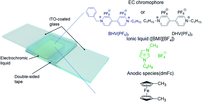 | ||
| Scheme 2 Schematic illustration of the ECD in this work and the chemical structures of the materials included in the EC layer. | ||
2.4 Characterizations
The redox behaviors of the viologens were examined using cyclic voltammetry (CV). Cyclic voltammograms were acquired on a potentiostat (Wave Driver 10, Pine Instrument) at a sweep rate of 25, 50, 80, and 100 mV s−1. The Pt disk, Ag wire, and ITO-coated glass were selected as the working, reference, and counter electrodes, respectively. The electrolyte-soluble anodic species, dmFc, was used as an internal standard for calibration. 1H NMR spectrum was recorded on Bruker digital Avance III 500 instrument using methanol-d4 (CD3OD) as a solvent. The voltage dependence of the optical properties and the estimation of response times for the ECDs were investigated using a UV-vis spectrometer (V-730, Jasco). The scan range and rate were 400–1100 nm and 400 nm min−1, respectively. The CIELAB color coordinates were extracted from the obtained UV-vis spectra using the Spectra Magic NX software, providing the L*, a*, and b* values. The external power was supplied from the same potentiostat or a source meter (Keithley 2400, Tektronix).3. Results and discussion
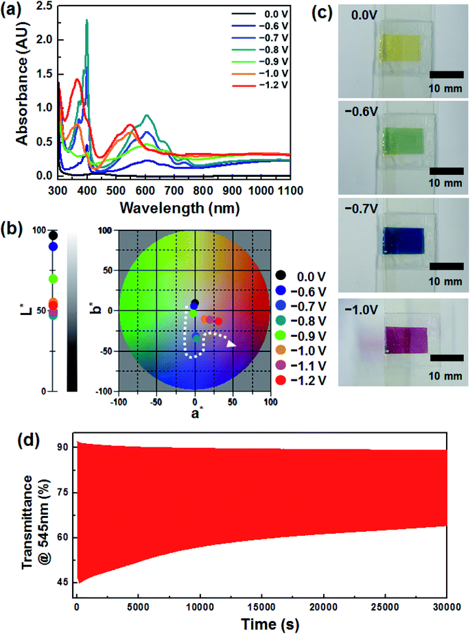
Fig. 1a shows the voltage dependence of the optical characteristics of the device, which included an EC layer consisting of DHV2+ (cathodic EC chromophore), dmFc (anodic non-EC species) and [BMI][BF4] (electrolyte). Under no bias, the weak absorption at ∼434 nm was simply observed, arising from the dissolved dmFc. When the applied voltage was −0.6 V, the coloration commenced with the reduction of DHV2+ to DHV+˙. The absorption spectrum, having a λmax of ∼605 nm, was fully developed at −0.8 V, which corresponds to a blue color (see Fig. 1b). However, when the applied voltage was further increased, dramatic changes in the spectra were recorded. For example, the intensity of the peaks at ∼605 and ∼400 nm was diminished and a new characteristic absorption at ∼545 and ∼366 nm corresponding to the dimers of DHV+˙ appeared. In addition, a* value (∼0.88 at −0.8 V) of the CIELAB color coordinate abruptly moved to a larger a* value of 13.29 at −1.0 V, corresponding to the transition bluish to reddish colored state (Fig. 1b).The sequential variations in color (i.e. transparent to blue to magenta) are clearly displayed in Fig. 1c. Such EC behaviors are highly related to the formation of dimers of radical cations. In general, the dimerization arising from spin-pairing becomes dominant, as the length of alkyl N-substituents on dialkyl viologens increases and hydrophilic electrolytes are employed.25–28 Also, we found that the magenta-colored dimer composed a majority of the colored species when the concentration of radical cations in the gel electrolyte was sufficient.29 In this work, similar coloration behaviors were observed from the ECD based on DHV2+ and [BMI][BF4], although no polymer gelator was included in the electrolyte. Therefore, the second coloration at applied voltages higher than −0.8 V could be explained by the dominant dimerization. However, the redox reaction of the dimers was quasi-reversible, so the coloration/bleaching cyclic stability was relatively lower. Fig. 1d shows the transient transmittance profile during the cyclic operation, for which the coloration and bleaching were conducted for 5 and 55 s each at −1.2 V and under a short circuit condition, respectively. The initial ΔT (ΔTo) at 545 nm was ∼46%, whereas only ∼54% of ΔTo (i.e. ΔT ∼ 25%) remained after continuous operation for 30![[thin space (1/6-em)]](https://www.rsc.org/images/entities/char_2009.gif) 000 s.
000 s.
Accordingly, the molecular modification of viologens to suppress the formation of quasi-reversible dimers is necessary to achieve highly stable ECDs. For this purpose, we propose asymmetric BHV2+ that involves a bulky benzyl N-substituent instead of one of the heptyl groups (see Schemes 1 and 2). The prepared molecular structure of BHV2+ was analyzed using 1H NMR. For example, two characteristics peaks corresponding to –CH2– of the benzyl and heptyl groups adjacent to the nitrogen were shown at ∼5.90 (singlet, peak b) and ∼4.70 ppm (triplet, peak f), respectively (see Fig. 2a). The integration area of peak b and f was determined to be 1.00 and 1.04, respectively, which supports that the target asymmetric viologen BHV2+ was successfully synthesized. The successful synthesis was further supported by 13C NMR, 19F NMR, and electrospray ionization mass spectroscopy (ESI-MS) (Fig. S1–S3 in ESI†). The electrochemical behaviors of BHV2+ are examined with CV (Fig. 2b). A [BMI][BF4] solution containing 0.05 M of BHV2+ (EC chromophore) and 0.05 M of dmFc (anodic species) was prepared, and the working electrode (WE), counter electrode (CE), and reference electrode (RE) were a Pt disk, ITO, and Ag wire, respectively. Cyclic voltammograms were recorded at four different scan rates. Irrespective of the scan rate, two redox peaks were clearly shown with high reversibility (ipc/ipa ∼ 0.99). In contrast, symmetric DHV2+ exhibited low reversibility of redox behaviors (Fig. S4 in ESI†). For example, the ipc/ipa was only ∼0.63 for DHV2+/DHV+˙ couple, which is due to the formation of quasi-reversible dimers of DHV+˙ in [BMI][BF4].
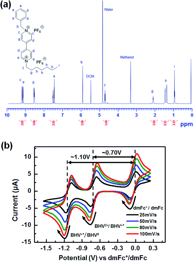 | ||
| Fig. 2 (a) 1H NMR spectrum of BHV(PF6)2. (b) Cyclic voltammograms of the EC system containing both BHV2+ and dmFc in [BMI][BF4]. | ||
To investigate the EC properties of BHV2+, the UV-vis absorption spectra were recorded at various applied voltages (Fig. 3a). Similar to the DHV2+ device (Fig. 1a), a broad and small peak at ∼434 nm originating from the dmFc was observed in the bleached state before the application of voltage. The characteristic absorption at ∼605 nm appeared at −0.6 V. Considering the onset potentials of the reduction (−0.62 V) of BHV2+ and oxidation (−0.07 V) of dmFc, the coloration voltage was in good agreement with the CV result (Fig. 2b). As the applied voltage increased, the absorption intensity of the UV-vis spectra was enhanced due to the presence of a larger amount of BHV+˙. It should be noted that characteristic absorptions at ∼605 and ∼400 nm did not change in contrast to the EC behavior of DHV2+ (see Fig. 1a), supporting the formation of less dimers. The changes in the CIELAB color coordinates are plotted in Fig. 3b. As the applied voltage increased to −1.2 V, the L* value decreased, indicating a large contrast of color intensity. While there was no remarkable change in a*, the b* values largely shifted to more negative values (e.g., −2.39 at −0.6 V to −48.19 at −1.2 V). Namely, the bluish colored state of the ECD containing BHV2+ did not change significantly. Photographs of the device at four different voltages display the corresponding EC behavior (Fig. 3c). Therefore, we conclude that a simple modification of the N-substituent of the viologens to achieve an asymmetric structure effectively diminished the formation of radical cation dimers.
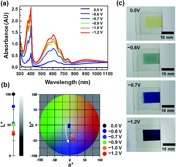 | ||
| Fig. 3 (a) Voltage dependence of UV-vis spectra of BHV2+. (b) Variation in CIELAB color coordinates (L*, a*, b*) of the ECD containing BHV2+. (c) Photographs of BHV2+ at various applied voltages. | ||
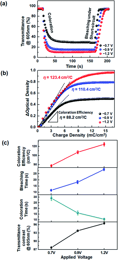
The device response during coloration and bleaching was also examined. We estimated the time required for a 90% change of ΔTmax, referred to as the response time (t), from the transient transmittance profiles during continual coloration and bleaching (Fig. 4a). It is noted that the application of voltages higher than −0.8 V was not suitable for DHV2+-based ECDs, because the dimerization of radical cations was accelerated and quasi-reversible magenta-colored dimers were produced. However, the use of asymmetric BHV2+ allowed the ECDs to operate at higher voltages. As a result, much shorter coloration time (tc ∼ 10.6 s) was achieved at −1.2 V, compared to the operation at −0.7 (tc ∼ 29.0 s) and −0.9 V (tc ∼ 16.0 s). The device colored at −1.2 V required a longer bleaching time due to the higher concentration of BHV+˙, similar to the viologen-based Type I ECDs.33,40,41
Coloration efficiency (η) values were compared at various voltages. The η is defined by η = ΔOD/ΔQ = log(Tb/Tc)/ΔQ, where ΔOD is the optical density contrast calculated by the logarithm of the transmittance ratio of bleached (Tb) and colored (Tc) states, and ΔQ is the amount of injected charge. The η value was extracted from the slope of a linear fit of the graphs of ΔOD vs. ΔQ given in Fig. 4b. We found that coloration was more efficient at a higher voltage: η at −0.7, −0.9, and −1.2 V were 88.2, 110.4, and 123.4 cm2 C−1, respectively. The increase in η at higher voltages may be attributed to the facilitated charge injection caused by the larger electron energy at a higher electrode potential. An overall comparison of the EC characteristics is shown in Fig. 4c. The operation at a higher voltage was beneficial, in terms of larger transmittance variation between colored and bleached states, faster coloration dynamics, and higher η. It should be noted that all of these advantages were obtained because the molecular asymmetry was properly controlled so as not to form a significant quantity of dimers.
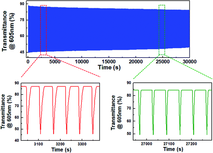
Eventually, the decrease in dimerization of BHV2+ resulted in the realization of highly stable ECDs. Fig. 5 shows the change in transmittance as a function of time during continual coloration/bleaching cycles. For a fair comparison with the ECD based on DHV2+, we set ΔTo at 605 nm to be ∼42%. A programmed voltage wave consisting of 5 s at −1.2 V followed by 55 s at 0.0 V was supplied from a potentiostat. ΔT was maintained at ∼82% of ΔTo even after 30![[thin space (1/6-em)]](https://www.rsc.org/images/entities/char_2009.gif) 000 s. Obviously, this result indicates a higher stability of BHV2+-based ECDs than DHV2+-based ECDs, as well as the importance and effectiveness of molecular tuning of EC chromophores.
000 s. Obviously, this result indicates a higher stability of BHV2+-based ECDs than DHV2+-based ECDs, as well as the importance and effectiveness of molecular tuning of EC chromophores.
4. Conclusions
In this work, we proposed a simple and effective strategy to suppress the dimerization of viologen radical cations. Molecular asymmetry was achieved by introducing a bulky benzyl N-substituent instead of one of the heptyl groups on DHV2+. The resulting BHV2+ exhibited a blue-colored state regardless of applied voltage level, implying a significantly reduced amount of dimerization, in contrast to DHV2+ in [BMI][BF4]. We took advantage of the high voltage operation and realized BHV2+-based ECDs exhibiting large transmittance contrast, faster coloration response, higher coloration efficiency, and good cyclic stability.Conflicts of interest
There are no conflicts to declare.Acknowledgements
This work was partly supported by Korea Institute of Energy Technology Evaluation and Planning (KETEP) grant funded by the Korea government (MOTIE) (20193020010370) and X-mind Corps program of National Research Foundation of Korea (NRF) funded by the Ministry of Science, ICT (NRF-2017H1D8A1030582).References
- P. M. S. Monk, R. J. Mortimer and D. R. Rosseinsky, Electrochromism and electrochromic devices, Cambridge University Press, Cambridge, UK, 2007 Search PubMed.
- R. J. Mortimer, D. R. Rosseinsky and P. M. S. Monk, Electrochromic materials and devices, Wiley-VCH, 2015 Search PubMed.
- H. C. Moon, T. P. Lodge and C. D. Frisbie, Chem. Mater., 2014, 26, 5358–5364 CrossRef CAS.
- H. C. Moon, T. P. Lodge and C. D. Frisbie, J. Mater. Chem. C, 2016, 4, 8448–8453 RSC.
- Y. M. Kim, D. G. Seo, H. Oh and H. C. Moon, J. Mater. Chem. C, 2019, 7, 161–169 RSC.
- K. Hong, M.-G. Kim, H. M. Yang, D. C. Lim, J. Y. Lee, S. J. Kim, I. Lee, K. H. Lee and J.-L. Lee, Adv. Energy Mater., 2016, 6, 1600651 CrossRef.
- E. Nossol and A. J. G. Zarbin, Sol. Energy Mater. Sol. Cells, 2013, 109, 40–46 CrossRef CAS.
- J. Jensen, M. V. Madsen and F. C. Krebs, J. Mater. Chem. C, 2013, 1, 4826–4835 RSC.
- S. Tsuneyasu, Y. Watanabe, K. Nakamura and N. Kobayashi, Sol. Energy Mater. Sol. Cells, 2017, 163, 200–203 CrossRef CAS.
- H. Oh, D. G. Seo, T. Y. Yun, C. Y. Kim and H. C. Moon, ACS Appl. Mater. Interfaces, 2017, 9, 7658–7665 CrossRef CAS PubMed.
- A. Llordés, G. Garcia, J. Gazquez and D. J. Milliron, Nature, 2013, 500, 323–326 CrossRef PubMed.
- J. Jensen and F. C. Krebs, Adv. Mater., 2014, 26, 7231–7234 CrossRef CAS PubMed.
- A. M. Österholm, D. E. Shen, J. A. Kerszulis, R. H. Bulloch, M. Kuepfert, A. L. Dyer and J. R. Reynolds, ACS Appl. Mater. Interfaces, 2015, 7, 1413–1421 CrossRef PubMed.
- G. Cai, P. Darmawan, M. Cui, J. Wang, J. Chen, S. Magdassi and P. S. Lee, Adv. Energy Mater., 2016, 6, 1501882 CrossRef.
- M. Vidotti and S. I. C. Torresi, Electrochim. Acta, 2009, 54, 2800–2804 CrossRef CAS.
- I. Bouessay, A. Rougier, P. Poizot, J. Moscovici, A. Michalowicz and J.-M. Tarascon, Electrochim. Acta, 2005, 50, 3737–3745 CrossRef CAS.
- R. J. Mortimer, Annu. Rev. Mater. Res., 2011, 41, 241–268 CrossRef CAS.
- J. H. Johnston, J. Moraes and T. Borrmann, Synth. Met., 2005, 153, 65–68 CrossRef CAS.
- A. Winter and U. S. Schubert, Chem. Soc. Rev., 2016, 45, 5311–5357 RSC.
- Y. Watanabe, K. Imaizumi, K. Nakamura and N. Kobayashi, Sol. Energy Mater. Sol. Cells, 2012, 99, 88–94 CrossRef CAS.
- B. Lim, S.-Y. Han, S.-H. Jung, Y. J. Jung, J. M. Park, W. Lee, H.-S. Shim and Y.-C. Nah, J. Ind. Eng. Chem., 2019, 80, 93–97 CrossRef CAS.
- H.-C. Lu, S.-Y. Kao, H.-F. Yu, T.-H. Chang, C.-W. Kung and K.-C. Ho, ACS Appl. Mater. Interfaces, 2016, 8, 30351–30361 CrossRef CAS PubMed.
- S.-Y. Kao, H.-C. Lu, C.-W. Kung, H.-W. Chen, T.-H. Chang and K.-C. Ho, ACS Appl. Mater. Interfaces, 2016, 8, 4175–4184 CrossRef CAS PubMed.
- K. C. Ho, Y. W. Fang, Y. C. Hsu and L. C. Chen, Solid State Ionics, 2003, 165, 279–287 CrossRef CAS.
- C. L. Bird and A. T. Kuhn, Chem. Soc. Rev., 1981, 10, 49–82 RSC.
- E. M. Kosower and J. L. Cotter, J. Am. Chem. Soc., 1964, 86, 5524–5527 CrossRef CAS.
- R. J. Mortimer and T. S. Varley, Chem. Mater., 2011, 23, 4077–4082 CrossRef CAS.
- L. Zhang, T. Y. Zhou, J. Tian, H. Wang, D. W. Zhang, X. Zhao, Y. Liu and Z. T. Li, Polym. Chem., 2014, 5, 4715–4721 RSC.
- T. Y. Yun and H. C. Moon, Org. Electron., 2018, 56, 178–185 CrossRef CAS.
- H. Oh, D. G. Seo, T. Y. Yun, S. B. Lee and H. C. Moon, Org. Electron., 2017, 51, 490–495 CrossRef CAS.
- J.-H. Ryu, M.-S. Park and K.-D. Suh, Colloid Polym. Sci., 2007, 285, 1675–1681 CrossRef CAS.
- Y. Alesanco, A. Viñuales, G. Cabañero, J. Rodriguez and R. Tena-Zaera, Adv. Opt. Mater., 2017, 5, 1600989 CrossRef.
- Y. Alesanco, A. Viñuales, G. Cabañero, J. Rodriguez and R. Tena-Zaera, ACS Appl. Mater. Interfaces, 2016, 8, 29619–29627 CrossRef CAS PubMed.
- A. L. de Lacey and V. M. Fernández, J. Electroanal. Chem., 1995, 399, 163–167 CrossRef.
- I. Pibiri, A. Beneduci, M. Carraro, V. Causin, G. Casella, G. A. Corrente, G. Chidichimo, A. Pace, A. Riccobono and G. Saielli, J. Mater. Chem. C, 2019, 7, 7974–7983 RSC.
- N. Jordão, L. Cabrita, F. Pina and L. C. Branco, Chem.–Eur. J., 2014, 20, 3982–3988 CrossRef PubMed.
- G. K. Pande, N. Kim, J. H. Choi, G. Balamurugan, H. C. Moon and J. S. Park, Sol. Energy Mater. Sol. Cells, 2019, 197, 25–31 CrossRef CAS.
- K. Madasamy, D. Velayutham, V. Suryanarayanan, M. Kathiresan and K.-C. Ho, J. Mater. Chem. C, 2019, 7, 4622 RSC.
- H. C. Moon, C. H. Kim, T. P. Lodge and C. D. Frisbie, ACS Appl. Mater. Interfaces, 2016, 8, 6252–6260 CrossRef CAS PubMed.
- K.-W. Kim, H. Oh, J. H. Bae, H. K. Kim, H. C. Moon and S. H. Kim, ACS Appl. Mater. Interfaces, 2017, 9, 18994–19000 CrossRef CAS PubMed.
- D. Barrios, R. Vergaz, J. C. Torres-Zafra, C. Vega, J. M. Sanchez-Pena and A. Viñuales, IEEE Photonics J., 2012, 4, 2105–2115 Search PubMed.
Footnote |
| † Electronic supplementary information (ESI) available. See DOI: 10.1039/c9ra09007j |
| This journal is © The Royal Society of Chemistry 2020 |


