DOI:
10.1039/C9RA08319G
(Paper)
RSC Adv., 2020,
10, 5666-5672
Multilayer carbon materials prepared from Zanthoxylum schinifolium husk for high-performance supercapacitors†
Received
12th October 2019
, Accepted 18th December 2019
First published on 4th February 2020
Abstract
In this work, porous carbon mixed with nitrogen (NC) prepared using Zanthoxylum schinifolium husk as a precursor has been successfully applied in a supercapacitor (SC). The effects of KOH dosage on the structure, composition and capacitive properties of the carbon were investigated by a variety of techniques (SEM, HRTEM, XRD, Raman spectroscopy, XPS, BET, and electrochemical tests). The results of physical characterizations also confirmed that NC had a high specific surface area, abundant pores and a large number of heteroatomic functional groups. Meanwhile, the sample exhibits the best electrochemical performance in a 6 M KOH electrolyte, including high specific capacitance (333.7 F g−1 at a current density of 0.5 A g−1), desirable rate capability and superior cycling stability (97.9% capacitance retention after 5000 cycles). More importantly, the assembled symmetrical supercapacitor (NC-3//NC-3) holds superior energy density (16.7 W h kg−1 at a power density of 300.6 W kg−1) and good cycling stability (98.5% specific capacitance retention after 5000 cycles).
1. Introduction
High-efficiency energy conversion and storage technologies are the major challenges and important opportunities for human beings at present.1–3 Among the advanced energy storage techniques, a supercapacitor with high power density, fast charge–discharge rate, and long cycle life has good application prospects in the portable energy storage field.4,5 According to different energy storage mechanisms, a supercapacitor can be divided into two types.6–8 One is an electric double-layer capacitor (EDLC), which relies on the electrostatic charge accumulation at the interface between the electrode and the electrolyte to store energy. The other is a pseudocapacitor, the charge storage of which depends on the fast reversible redox reactions occurring on the surface of the electrodes. Among the EDLC electrode materials, porous carbons with large active surfaces, excellent stability, and good electrical conductivity have good application prospects.
In recent years, excellent carbon materials have been obtained by carbonizing and activating pore formation in biomass materials. As reported, cornstalks, rice husks, seaweeds, fungi, shrimp shells, egg whites, gelatin, etc. have been successfully used to prepare activated carbon with excellent capacitance properties.9–11 Biomass materials with abundant heteroatoms, such as O, N, and S, have excellent pore structures and rich functional groups of heteroatoms.12–14 The abundant functional groups on the surface of carbon materials and their crystal structures improve their wettability and pseudo-capacitance.15 Therefore, the preparation of biomass-based carbon materials with more connected channels and more active functional groups has been an important research direction.16,17
Herein, porous carbon having abundant nitrogen functional groups is prepared by KOH activation in a tube furnace. The raw material Zanthoxylum schinifolium husk (ZSH) is easy to obtain and has a high heteroatom content; thus, it is a promising raw material for producing nitrogen-rich porous carbon. In this work, by choosing ZSH as a new precursor, we successfully prepared nitrogen self-doped layered porous carbon (NC) via combining carbonization and activation processes. By changing the KOH dosage, we obtained carbon materials with different pore structures and nitrogen contents.18–20 Compared with the traditional carbon materials,21–23 our work demonstrates the following advantages: (1) carbon has abundant pore and open layer structures. Uniform and interconnected pore structures endow plentiful active sites and shorten the ion diffusion length remarkably, facilitating the ion transport and storage in electrode materials. (2) NC with heteroatom-enriched surface functional groups can contribute to additional pseudo-capacitance. In fact, NC displays outstanding electrochemical performance in electrochemical tests. NC possesses high specific capacitance, excellent rate capability, and good cyclic stability. Furthermore, the symmetric supercapacitor (noted as NC-3//NC-3) assembled in this study has a broad operating potential of 1.5 V and delivers high energy density. In addition, the method reported in this article is applicable to different biomass materials.
2. Experimental
2.1 Materials
ZSH was purchased from YongHui supermarket (Shapingba, Chongqing, China). Hydrochloric acid and ethanol were bought from Sinopharm Chemical Reagent Co., Ltd (China). Potassium hydroxide was acquired from Shanghai Aladdin Biochemical Technology Co., Ltd (China). Polytetrafluoroethylene (PTFE) solution (60%) and acetylene black were obtained from Shanghai Macklin Biochemical Co., Ltd (China). Deionized water was obtained using the equipment of KMR-10 (Chengdu Haochun instrument equipment Co., Ltd, China). Nickel foam (1 cm × 2 cm) was obtained from Changde Lyrun Material Co., Ltd (Beijing, China).
2.2 Preparation of nitrogen-doped layered porous carbon
ZSH was soaked and washed with deionized water. After drying at 60 °C, ZSH was transferred into a tube furnace to be carbonized at 500 °C for 2 h with a heating rate of 1 °C min−1 under N2. After cooling down to room temperature, the pre-carbonized ZSH (denoted as PNC) was mixed with KOH in crucibles according to certain mass ratios. Then the crucibles were put into a tube furnace to be activated at 500 °C for 2 h with a heating rate of 5 °C min−1 under N2. Finally, the carbon materials obtained after cooling down to room temperature were washed with 2 M HCl and deionized water and then dried at 60 °C. The obtained samples are denoted as NC-x, where x (x = 2, 3, or 4) represents the mass ratio of KOH to PNC (Fig. 1).
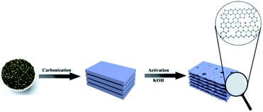 |
| | Fig. 1 Schematic of NC preparation. | |
2.3 Material characterization
The crystal structure of the material was determined by a polycrystal X-ray powder diffractometer (Lab XRD-6100, Japan) with Cu Kα radiation (λ = 1.5406 Å). The specific surface area and pore size distribution of the as-prepared carbon materials were measured by an N2 adsorption/desorption analyzer (3H-2000PS1, Beijing Beide Instrument Technology Co. Ltd.). The graphitization degree was measured by a laser confocal Raman spectrometer (Horiba Evolution) with an argon ion laser (λ = 532 nm). The elemental composition was studied by X-ray photoelectron spectroscopy (XPS; Thermo ESCALAB 250XI). The morphology and microstructure were analyzed by field emission scanning electron microscopy (SEM; SU8000, Hitachi Co.) and high-resolution field emission transmission electron microscopy (HRTEM; JEOL JEM 2100F). The electrochemical characterizations were performed using an electrochemical workstation (Shanghai Chenhua CHI660E, China).
2.4 Electrochemical measurements
The electrochemical tests of the materials were conducted by a three-electrode system in 6 M KOH electrolyte at room temperature, with a platinum electrode and an Hg/HgO electrode as the counter electrode and reference electrode, respectively. To fabricate working electrodes, the active material, acetylene black and the binder polytetrafluoroethylene (PTFE) were mixed in a mass ratio of 80![[thin space (1/6-em)]](https://www.rsc.org/images/entities/char_2009.gif) :10:10, followed by the addition of absolute ethanol to make the mixture into a uniform slurry. Then, the slurry was smeared on a 1 × 2 cm2 substrate of nickel foam and dried at 60 °C; the nickel foam was washed with hydrochloric acid, ethanol, and deionized water ahead of time. Finally, the above-mentioned materials were pressed into electrode slices under 10 MPa pressure. The mass of NC active material on each electrode was about 2–3.0 mg.
:10:10, followed by the addition of absolute ethanol to make the mixture into a uniform slurry. Then, the slurry was smeared on a 1 × 2 cm2 substrate of nickel foam and dried at 60 °C; the nickel foam was washed with hydrochloric acid, ethanol, and deionized water ahead of time. Finally, the above-mentioned materials were pressed into electrode slices under 10 MPa pressure. The mass of NC active material on each electrode was about 2–3.0 mg.
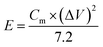
The symmetric supercapacitor NC-3//NC-3 was assembled by symmetrical NC electrodes with a polyester fiber paper as the separator. Its electrochemical measurements were carried out in a two-electrode system with 6 M KOH electrolyte at room temperature. In order to achieve a charge storage balance, the active material load masses of the two electrodes in NC-3//NC-3 are approximately equal. The specific capacitance of the electrode was calculated by the following equation:
| |
 | (1) |
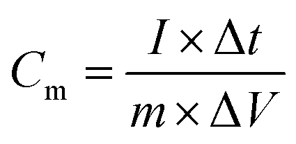
Here,
Cm (F g
−1) is the specific capacitance,
I (A) is the discharge current, Δ
t (s) is the discharge time,
m (g) is the active material mass and Δ
V (V) is the potential window.
The energy density and power density of the supercapacitor were calculated according to the following eqn (2) and (3), respectively:
| |
 | (2) |
| |
 | (3) |
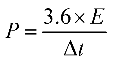
Here,
E (W h kg
−1) is the energy density,
Cm (F g
−1) is the specific capacitance, Δ
V (V) is the discharge potential range,
P (kW kg
−1) is the power density and Δ
t (s) is the discharge time.
Cyclic voltammetry (CV), galvanostatic charge–discharge (GCD) tests and electrochemical impedance spectroscopy (EIS) were carried out on a CHI660E electrochemical workstation.
3. Results and discussion
3.1 Material characterization
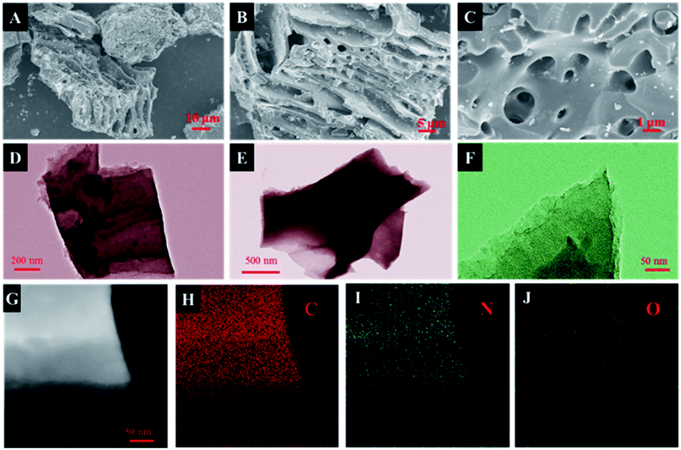
The morphology of the obtained samples was observed by SEM and HRTEM (Fig. 2, S2†). As depicted in Fig. 2A, the carbonized ZSH has a natural layered structure that can be easily infiltrated by electrolytes. It has been found that KOH is capable of etching the carbon framework to form a porous structure. The main mechanism of this process was proposed: KOH reacts with the precursor to generate H2O, CO, CO2, K2O, K2CO3, and K at the beginning of the process.24,25 Then, pores are further created in the carbon through the gasification process, which is attributed to the formation of H2O and CO2. In fact, after KOH etching at a high temperature, large amounts of pores and channels were generated in NC-3 (Fig. 2C). Moreover, NC-3 (Fig. 2D–F) further confirmed its layered structure, which provided large active surfaces and open ion diffusion channels.26 The EDS mapping of NC-3 (Fig. 2H–J) indicated that the NC-3 surface is rich in heteroatoms (N and O), and this coincided with the XPS result. Heteroatom doping can effectively improve the wettability and electronic conductivity of carbon materials.16,27
 |
| | Fig. 2 (A–C) SEM images and (D–G) HRTEM images of NC-3; (H–J) EDS mappings of NC-3. | |
Fig. 3A shows the X-ray diffraction patterns of all samples. Two primary peaks at 25.2° and 43.6° are observed, which correspond to the (002) and (101) planes of the graphitic carbon. The shift in the (002) crystal plane diffraction peak of the NC-x samples was towards a smaller angle than that observed for NC, demonstrating that layer spacing increased because metallic K efficiently intercalated into the carbon lattices of the carbon matrix during activation, which resulted in the expansion of the carbon lattices. After the removal of the intercalated metallic K and other K compounds by washing, the expanded carbon lattices could not return to their previous non-porous structures and thus, a large lattice spacing was created.28 Besides, the graphitization degree of the samples was further determined by Raman spectroscopy. As shown in Fig. 3B, three materials exhibit two obvious peaks at ∼1346 cm−1 (D band) and ∼1591 cm−1 (G band), which are related to the disordered structures and graphitic texture, respectively.29,30 Obviously, the graphitization degree gradually declined with the increase in the KOH dosage, which led to the formation of defects.
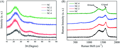 |
| | Fig. 3 XRD patterns (A) and Raman spectra (B) of NC and NC-x (2, 3, 4). | |
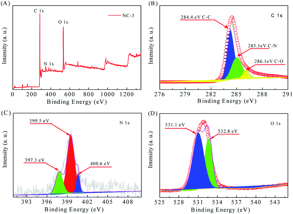
XPS analysis (Fig. 4) was conducted to determine the surface chemical composition. From the survey spectrum in Fig. 4A, we infer that the sample NC-3 mainly contains C, O and N elements without other metal atoms. In the C 1s spectrum (Fig. 4B), there are three kinds of C states: C–C (284.4 eV), C–N (285.1 eV) and C–O (286.1 eV).27,31 In the N 1s spectrum (Fig. 4C), the three individual peaks located at 397.3 eV, 399.5 eV and 400.6 eV represent pyridinic-N (N-6), pyrrolic-N (N-5) and quaternary-N (N-Q) and oxidized-N (N-X), respectively. As reported, N-6 and N-5 distributed on the material surface and edges are the main providers of pseudo-capacitance.32,33 Meanwhile, the presence of N-Q can promote electron transfer and enhance conductivity. Therefore, the high-content N with surface activity plays an important role in improving the capacitance performance of the carbon material.34 The O 1s spectrum (Fig. 4D) fits well with the two peaks at 531.1 eV and 532.8 eV, which are assigned to CO and COH/COC, respectively. In conclusion, these N and O-based surface functional groups can change the atomic arrangement order, increase the reactive sites, and enhance the conductivity, thus improving the capacitive performance of the material.5,35
 |
| | Fig. 4 XPS spectra of NC-3: (A) survey spectrum, (B) C 1s, (C) N 1s and (D) O 1s. | |
The specific surface area (SBET) and pore size distribution of NC-x (x = 2, 3, and 4) were measured by nitrogen adsorption–desorption (Table 2). The specific surface area of NC was significantly smaller than that of the activated sample. As shown in Fig. 5, samples NC, NC-2, and NC-3 display type-IV N2 adsorption/desorption isotherms but NC-4 displays a type-I isotherm. This is because the number of micropores increases with the increase in potassium hydroxide, which keeps on reacting with carbon atoms, causing an increase in the pore size and disappearance of the hysteresis loop.28 At a low relative pressure (P/P0 < 0.2), the adsorption capacity increases rapidly. However, when the relative pressure increases further, the amount of adsorption is saturated and this gradually forms a plateau, revealing the presence of a microporous structure and narrow pore size distribution.36 Among them, NC-3 has the largest specific surface area. NC-2 has a smaller specific surface area due to insufficient activation degree. The reduced specific surface area of NC-4 may be because of excess KOH, leading to pore collapse. Therefore, a reasonable activator amount is critical for the preparation of high-performance carbon.19,37 As for NC-3, its appropriate pore size distribution and large specific surface area can effectively enhance the wettability of the material and accelerate ion transfer, leading to improved capacitive properties.38
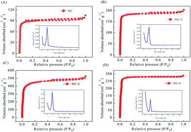 |
| | Fig. 5 N2 adsorption/desorption isotherms and pore size distribution curves of NC and NC-x (2, 3, 4) (A–D). | |
3.2 Electrochemical performance
The electrochemical behavior of NC electrodes (Fig. 6) was investigated in a three-electrode system with a 6 M KOH electrolyte. In Fig. 6A, all CV curves at a scan rate of 5 mV s−1 with the potential window from −1 to 0 V show a quasi-rectangular shape, indicating a typical behavior of double-layer capacitance. In addition, the apparent humps in the CV curve imply the presence of pseudocapacitance generated by the redox reactions of heteroatomic functional groups, such as C–N, C![[double bond, length as m-dash]](https://www.rsc.org/images/entities/char_e001.gif) N, C–O, CO, and N–O.35 It is worth noting that the CV curve of NC-3 shows the highest capacitance, indicating that its layered structure and suitable pore size distribution are more conducive to ion transmission, and its higher heteroatom content can generate more pseudo-capacitance, thus obtaining better capacitance.39 The CV curves of NC-3 (Fig. 6B) show no obvious distortion when the scan rate changes from 5 to 100 mV s−1, suggesting the ideal capacitive behavior with fast charge–discharge ability and excellent multiplier performance. Fig. 6C displays the GCD curves of the samples at the current density of 0.5 A g−1. The slightly curved shape of the GCD curves further indicates the coexistence of double-layer capacitance and pseudo-capacitance.2,6 From Fig. 6D, it can be seen that the GCD curves of NC-2 always maintain good symmetry at different current densities, proving the excellent material reversibility. As a result, the NC-3 electrode provided more impressive capacity retention, excellent cycling stability and outstanding electrochemical performance (Fig. S4†).
N, C–O, CO, and N–O.35 It is worth noting that the CV curve of NC-3 shows the highest capacitance, indicating that its layered structure and suitable pore size distribution are more conducive to ion transmission, and its higher heteroatom content can generate more pseudo-capacitance, thus obtaining better capacitance.39 The CV curves of NC-3 (Fig. 6B) show no obvious distortion when the scan rate changes from 5 to 100 mV s−1, suggesting the ideal capacitive behavior with fast charge–discharge ability and excellent multiplier performance. Fig. 6C displays the GCD curves of the samples at the current density of 0.5 A g−1. The slightly curved shape of the GCD curves further indicates the coexistence of double-layer capacitance and pseudo-capacitance.2,6 From Fig. 6D, it can be seen that the GCD curves of NC-2 always maintain good symmetry at different current densities, proving the excellent material reversibility. As a result, the NC-3 electrode provided more impressive capacity retention, excellent cycling stability and outstanding electrochemical performance (Fig. S4†).
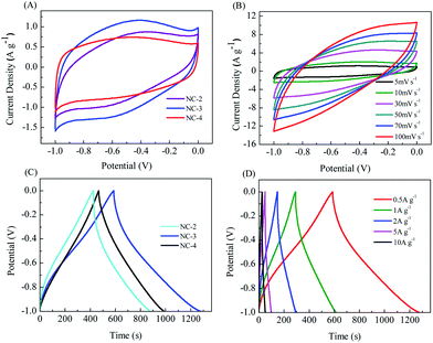 |
| | Fig. 6 Electrochemical properties of NC-x (2, 3, 4) measured in 6 M KOH: (A) CV curves of NC-x at 5 mV s−1. (B) CV curves of NC-3 from 5 to 100 mV s−1. (C) GCD curves of NC-x at 0.5 A g−1 and (D) GCD curves of NC-3 from 0.5 to 10 A g−1. | |
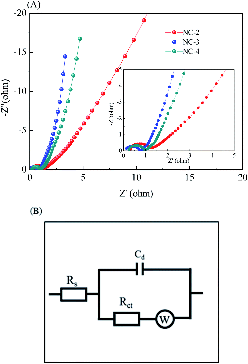
To further investigate the behavior of the NC electrode for supercapacitors, electrochemical impedance spectroscopy (EIS, Fig. 7A) was carried out in a frequency range from 10−2 Hz to 104 Hz. The inset shows the equivalent circuit for the fitting of the EIS data, where Rs is the solution resistance, Cd is double-layer capacitance, Rct is the charge transfer resistance, and W is the Warburg impedance (Fig. 7B). It can be observed that the Nyquist plot has two distinct parts: a semicircle part at a high frequency and a linear part at a low frequency. At a high frequency, the solution resistance and the charge transfer resistance can be obtained from the intercept at the real axis (Z′) and the semicircle intercepts in the Nyquist plot, respectively. According to this fitting result, the Rs values (Table 1) of NC-2, NC-3, and NC-4 are calculated to be 0.31, 0.15 and 0.32 Ω, respectively. As expected, NC-3 has the lowest equivalent series resistance, suggesting good contact between the electrolyte and the active material. Meanwhile, the Rct value (Table 1) of NC-3 is 0.61 Ω, which is lower than those of NC-2 (0.87 Ω) and NC-4 (0.69 Ω), indicating its better charge transfer capability and electrical conductivity. Besides, the steep line at a low frequency reveals the relatively small W of NC-3, manifesting the easy intercalation and deintercalation of ions in the electrode. These superiorities of NC-3 are largely ascribed to the following two reasons: (1) the abundant micropores and large specific surface area of the sample can increase the contact area between the electrode and the electrolyte, thus providing more electroactive sites;37 (2) the layered structure can enhance the wettability of the material and facilitate charge transfer and ion diffusion.40,41
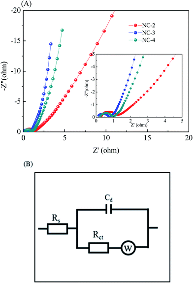 |
| | Fig. 7 (A) Nyquist plots and (B) equivalent-circuit diagram of NC-x (2, 3, 4). | |
Table 1 Rs/Rct of NC and NC-x (2, 3, 4)
| Sample |
Rs (Ω) |
Rct (Ω) |
| NC-2 |
0.31 |
0.87 |
| NC-3 |
0.15 |
0.61 |
| NC-4 |
0.32 |
0.69 |
Table 2 The BET surface area, coulombic efficiency, ID/IG, layer spacing, yield of NC and NC-x (2, 3, 4)
| Sample |
SBETa (m2 g−1) |
C (%) |
ID/IG |
Layer spacingb |
Yieldc (%) |
| The SBET was determined by using multi-point BET method. Layer spacing of (002) crystal plane. Yield is before and after carbonization of NC, yield is before and after activation of NC-2, NC-3, and NC-4. |
| NC |
277.4698 |
79.6 |
0.6960 |
3.769 |
91.6 |
| NC-2 |
740.7407 |
90.3 |
0.8985 |
3.927 |
96.7 |
| NC-3 |
1473.6663 |
97.9 |
0.8792 |
3.935 |
94.3 |
| NC-4 |
864.7580 |
93.7 |
0.9823 |
3.944 |
92.1 |
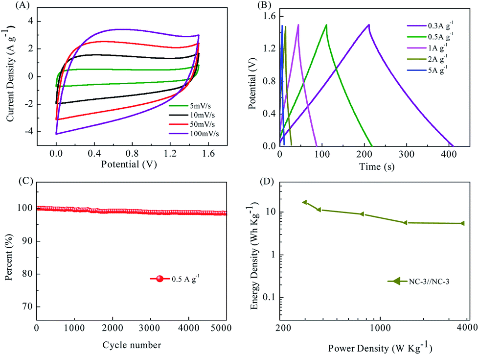
Electrochemical tests were also carried out in a two-electrode symmetric cell with the same mass loading on both the positive and negative electrodes.9 NC-3 exhibited the best capacitive performance in the aforementioned three-electrode system. Its electrochemical properties were further investigated in a two-electrode system. Fig. 8A displays the CV curves for the symmetric supercapacitor assembled using NC-3 operated in different voltage windows ranging from 5 to 50 mV s−1 within the voltage window of 0–1.5 V. The CV curves for the symmetric supercapacitor exhibit a rectangular shape at sweep rates. The GCD curves of NC-3//NC-3 show a nearly symmetrical triangular shape even at a current density as high as 5 A g−1 (Fig. 8B), implying the ideal capacitive behavior of the carbon. In addition, no obvious IR drop is observed even at high current densities, indicating its high charge–discharge efficiency and low internal resistance due to the fast charge transfer and ion diffusion.42 NC-3//NC-3 also has excellent cycle performance (Fig. 8C, still retaining 98.5% capacitance after 5000 times of charge/discharge) and high energy density and power density (Fig. 8D). Combined with the electrochemical data, this work transforms the ZSH biomass into a carbon material with a high specific surface area and achieves excellent performance of the supercapacitor. This is beneficial for the conversion of biomass materials into energy storage materials.
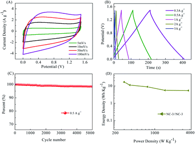 |
| | Fig. 8 Capacitive properties of the NC-3//NC-3 symmetric supercapacitor tested in 6 M KOH: (A) CV curves at various scan rates. (B) GCD curves at various current densities. (C) Cyclic stability of NC-3//NC-3 at a charge–discharge current density of 0.5 A g−1 for 5000 cycles. (D) Ragone plot of NC-3//NC-3. | |
4. Conclusion
In this work, green renewable Zanthoxylum schinifolium husk was transformed into a porous multi-layered carbon material by a simple carbonization-activation two-step method. In addition, the mass ratios between ZSH and KOH (1:2, 1:3, and 1:4) were determined to influence the structure and the capacitance properties of the activated carbon materials. The results showed that NC-3 had the most reasonable pore structure and the best capacitive performance. In particular, hybrid functional groups and layered porous structures improved the capacitive properties of the carbon materials. The layered porous structure not only provided open channels for ion transmission but also shortened the diffusion path of ions, promoting the rapid transmission of electrolyte ions and effectively alleviating the volume expansion and deformation in the cycle process. In addition, the abundant N, C, and O functional groups could not only improve the infiltration of the electrode surface, but also provide additional Faraday capacitors, thus improving the energy storage performance of the material. The electrochemical test results also showed that NC-3 has the best electrochemical performance. When the current density was 0.5 A g−1, the specific capacitance was as high as 333.7 F g−1, and the capacitance could be maintained at 97.9% even after 5000 charge/discharge cycles. The symmetrical capacitor NC-3//NC-3 can be constructed, and it can exhibit high energy density and power density.
Conflicts of interest
There are no conflicts to declare.
Acknowledgements
The authors are thankful for financial supports obtained from the Program of Chongqing Research Program of Basic Research and Frontier Technology (No. cstc2018jcyjA2390) and Chongqing Education Committee Science and Technology Research Project (No. KJ130650).
References
- Y. Yuan, R. Yi, Y. Sun, J. Zeng, J. Li, J. Hu, Y. Zhao, W. Sun, C. Zhao, L. Yang and C. Zhao, J. Nanomater., 2018, 2018, 1–10 Search PubMed.
- Z. Bi, Q. Kong, Y. Cao, G. Sun, F. Su, X. Wei, X. Li, A. Ahmad, L. Xie and C.-M. Chen, J. Mater. Chem. A, 2019, 7, 16028–16045 RSC.
- H. Lu and X. S. Zhao, Sustainable Energy Fuels, 2017, 1, 1265–1281 RSC.
- T. Ouyang, K. Cheng, F. Yang, L. Zhou, K. Zhu, K. Ye, G. Wang and D. Cao, J. Mater. Chem. A, 2017, 5, 14551–14561 RSC.
- L. Zhang, F. Zhang, X. Yang, K. Leng, Y. Huang and Y. Chen, Small, 2013, 9, 1342–1347 CrossRef CAS PubMed.
- X.-L. Su, J.-R. Chen, G.-P. Zheng, J.-H. Yang, X.-X. Guan, P. Liu and X.-C. Zheng, Appl. Surf. Sci., 2018, 436, 327–336 CrossRef CAS.
- S. Yang, S. Wang, X. Liu and L. Li, Carbon, 2019, 147, 540–549 CrossRef CAS.
- H. Chen, D. Liu, Z. Shen, B. Bao, S. Zhao and L. Wu, Electrochim. Acta, 2015, 180, 241–251 CrossRef CAS.
- S. Song, F. Ma, G. Wu, D. Ma, W. Geng and J. Wan, J. Mater. Chem. A, 2015, 3, 18154–18162 RSC.
- F. Zeng, Z. Li, X. Li, J. Wang, Z. Kong, Y. Sun, Z. Liu and H. Feng, Appl. Surf. Sci., 2019, 467–468, 229–235 CrossRef CAS.
- G. Zhao, C. Chen, D. Yu, L. Sun, C. Yang, H. Zhang, Y. Sun, F. Besenbacher and M. Yu, Nano Energy, 2018, 47, 547–555 CrossRef CAS.
- B. D. Boruah and A. Misra, ACS Appl. Energy Mater., 2019, 2, 278–286 CrossRef CAS.
- C. Chen, D. Yu, G. Zhao, B. Du, W. Tang, L. Sun, Y. Sun, F. Besenbacher and M. Yu, Nano Energy, 2016, 27, 377–389 CrossRef CAS.
- X. Zhou, H. Li and J. Yang, J. Energy Chem., 2016, 25, 35–40 CrossRef.
- C. H. Ng, H. N. Lim, S. Hayase, Z. Zainal, S. Shafie, H. W. Lee and N. M. Huang, ACS Appl. Energy Mater., 2018, 1, 692–699 CrossRef CAS.
- M. P. Down, S. J. Rowley-Neale, G. C. Smith and C. E. Banks, ACS Appl. Energy Mater., 2018, 1, 707–714 CrossRef CAS.
- H. Wang, W. Wang, H. Wang, X. Jin, H. Niu, H. Wang, H. Zhou and T. Lin, ACS Appl. Energy Mater., 2018, 1, 431–439 CrossRef CAS.
- Y. Qing, Y. Jiang, H. Lin, L. Wang, A. Liu, Y. Cao, R. Sheng, Y. Guo, C. Fan, S. Zhang, D. Jia and Z. Fan, J. Mater. Chem. A, 2019, 7, 6021–6027 RSC.
- Y. Xie, L. Wang, Q. Guo, J. Yin, J. Liu, L. Fan and J. Wu, J. Mater. Sci. Mater. Electron., 2018, 29, 7957–7964 CrossRef CAS.
- M. P. Down, S. J. Rowley-Neale, G. C. Smith and C. E. Banks, ACS Appl. Energy Mater., 2018, 1, 707–714 CrossRef CAS.
- V. T. Le, H. Kim, A. Ghosh, J. Kim, J. Chang, Q. A. Vu, D. T. Pham, J.-H. Lee, S.-W. Kim and Y. H. Lee, ACS Nano, 2013, 7, 5940–5947 CrossRef CAS PubMed.
- S. D. B. K. Sharma, A. Stoesser, S. K. Mondal, S. K. Garlapati, M. H. Faway, V. S. K. Chakravadhanula, R. Kruk and H. Hahn, ACS Appl. Mater. Interfaces, 2018, 10, 22408–22418 CrossRef PubMed.
- C. Sasirekha, S. Arumugam and G. Muralidharan, Appl. Surf. Sci., 2018, 521–527 CrossRef CAS.
- A. Durairaj, T. Sakthivel, S. Ramanathan, A. Obadiah and S. Vasanthkumar, Cellulose, 2019, 26, 1–12 CrossRef.
- L. Cheng, H. H. Yu, J. W. Yong, J. Li and P. C. Ji, J. Power Sources, 2018, 394, 9–16 CrossRef.
- Y. Wu, Y. Yang, X. Zhao, Y. Tan, L. Ying, W. Zhen and F. Ran, Nano-Micro Lett., 2018, 10, 63 CrossRef PubMed.
- K. Li, W. Bin Zhang, Z. Y. Zhao, Y. Zhao, X. W. Chen and L. Bin Kong, Mater. Res. Express, 2018, 5, 025514 CrossRef.
- J. Wang and S. Kaskel, J. Mater. Chem., 2012, 22, 23710–23725 RSC.
- L. Shi, L. Jin, Z. Meng, Y. Sun, C. Li and Y. Shen, RSC Adv., 2018, 8, 39937–39947 RSC.
- W. Zhang, J. Xu, D. Hou, J. Yin, D. Liu, Y. He and H. Lin, J. Colloid Interface Sci., 2018, 530, 338–344 CrossRef CAS PubMed.
- Y. Xie, L. Wang, Q. Guo, Y. Jie, L. Jia, L. Fan and J. Wu, J. Mater. Sci. Mater. Electron., 2018, 29, 1–8 CrossRef.
- L. Shi, L. Jin, Z. Meng, Y. Sun, C. Li and Y. Shen, RSC Adv., 2018, 8, 39937–39947 RSC.
- A. Subagio, A. Darari, I. S. Hakim and A. Subhan, Mater. Sci. Forum, 2018, 929, 121–127 Search PubMed.
- S. Chen, J. Liang, J. Zhao, H. Li, Y. Liu, H. Deng, C. Liu, S. Tang and Y. C. Cao, Chin. Chem. Lett., 2019, 3, 787–791 CrossRef.
- Y. Zhu, T. Fang, J. Hua, S. Qiu, H. Chu, Y. Zou, C. Xiang, P. Huang, K. Zhang, X. Lin, E. Yan, H. Zhang, F. Xu, L. Sun and J. Zeng, ChemistrySelect, 2019, 4, 7358–7365 CrossRef CAS.
- G. Zhao, Y. Li, G. Zhu, J. Shi, T. Lu and L. Pan, Ionics, 2019, 25, 3935–3944 CrossRef CAS.
- Y. Luan, Y. Huang, L. Wang, M. Li, R. Wang and B. Jiang, J. Electroanal. Chem., 2016, 763, 90–96 CrossRef CAS.
- S. Zhang, Y. Pang, Y. Wang, B. Dong, S. Lu, M. Li and S. Ding, J. Alloys Compd., 2018, 735, 1722–1729 CrossRef CAS.
- B. Zhu, B. Liu, C. Qu, H. Zhang, W. Guo, Z. Liang, F. Chen and R. Zou, J. Mater. Chem. A, 2018, 6, 1523–1530 RSC.
- P.-W. Xiao, Q. Meng, L. Zhao, J.-J. Li, Z. Wei and B.-H. Han, Mater. Des., 2017, 129, 164–172 CrossRef CAS.
- C. Liang, J. Bao, C. Li, H. Huang, C. Chen, Y. Lou, H. Lu, H. Lin, Z. Shi and S. Feng, Microporous Mesoporous Mater., 2017, 251, 77–82 CrossRef CAS.
- L. Qiang, Z. Hu, Z. Li, Y. Yang, X. Wang, Y. Zhou, X. Zhang, W. Wang and Q. Wang, J. Porous Mater., 2019, 26, 1217–1225 CrossRef CAS.
Footnote |
| † Electronic supplementary information (ESI) available. See DOI: 10.1039/c9ra08319g |
|
| This journal is © The Royal Society of Chemistry 2020 |
Click here to see how this site uses Cookies. View our privacy policy here. 
 Open Access Article
 This Open Access Article is licensed under a Creative Commons Attribution-Non Commercial 3.0 Unported Licence
 *ab,
Liu Yanga,
Shuya Wangc and
Lian Liua
*ab,
Liu Yanga,
Shuya Wangc and
Lian Liua