 Open Access Article
Observing the three-dimensional terephthalic acid supramolecular growth mechanism on a stearic acid buffer layer by molecular simulation methods†
Chia-Hao Su‡
a,
Hui-Lung Chen‡b,
Shih-Jye Sunc,
Shin-Pon Ju *de,
Tsu-Hsun Houd and
Che-Hsin Lin
 d
d
aInstitute for Translational Research in Biomedicine, Kaohsiung Chang Gung Memorial Hospital, Kaohsiung 833, Taiwan
bDepartment of Chemistry and Institute of Applied Chemistry, Chinese Culture University, Taipei 111, Taiwan
cDepartment of Applied Physics, National University of Kaohsiung, Kaohsiung 811, Taiwan
dDepartment of Mechanical and Electro-Mechanical Engineering, National Sun Yat-sen University, Kaohsiung 804, Taiwan. E-mail: jushin-pon@mail.nsysu.edu.tw
eDepartment of Medicinal and Applied Chemistry, Kaohsiung Medical University, Kaohsiung 807, Taiwan
First published on 8th January 2020
Abstract
The terephthalic acid (TPA) supramolecular growth mechanisms on the stearic acid (STA) buffer layer, such as the phase separation and layer-by-layer (LBL) mechanisms, were considered by molecular simulations. The electrostatic surface potential (ESP) charges obtained by the semi-empirical ab initio package VAMP with PM6 were used with the Dreiding force field. The stochastic tunneling-basin hopping-discrete molecular dynamics method (STUN-BH-DMD) was first used to construct the most stable STA buffer layers (STA100, STA120, and STA140) on graphene. At STA100 and STA120, the STA molecule stacking along their long axis is the major mechanism to obtain the stable STA buffer layer. At STA140, the hydrogen bond network between the terminal COOH groups of STA molecules makes the STA buffer layer the most stable, leading to a higher disintegration temperature among all STA coverages. In the early growth of the TPA supramolecule, TPA molecules were first adsorbed by the holes between STA piles. At STA100 and STA120, the subsequent TPA molecules were adsorbed by the TPA molecules within the holes, leading to the phase separation growth. At STA140, the TPA supramolecule tends to grow by the LBL mechanism.
Introduction
Advanced self-assembly technology has allowed novel two-dimensional (2D) nanostructure materials to become widespread.1 Among these nanomaterials, the 2D supramolecule is made up of one or several types of molecules through the self-assembly process, which forms an ultra-thin film on a substrate.2,3 The self-assembled 2D supramolecule nanostructure is generally monotonic and its pattern is also straight-forward to control. Accordingly, different 2D supramolecules have been extensively used in many fields, such as for anticancer drug delivery,4,5 gene delivery, photothermal therapy (PTT), photodynamic therapy (PDT), biosensing, and regenerative medicine.6Since 2D supramolecules are mainly formed by the ordered arrangement of compositional molecules on the substrate, two key factors in constructing such a 2D supramolecule with specific textures are the relative orientations of the compositional molecules as well as the molecule's orientation to the substrate.7 Consequently, understanding at the atomic scale how compositional molecules arrange themselves on the substrate is key to developing new 2D supramolecules. An analysis of the ordered pattern of compositional molecular arrangements observed by scanning tunneling microscopy (STM)8,9 indicates that these compositional molecules are stabilized by the intermolecular hydrogen bonds and van der Waals force.10 Moreover, the textures of self-assembled supramolecules can be tailored by using molecules with different chirality,10,11 substrates with different surface facets,12 different fragment positions of functional groups,13 and side chains of different lengths.14 For example, Liu focused on the self-assembly process of hydrogen-bonded supramolecular complexes of nucleic-acid–base (guanine, G) and fatty-acid (SA) molecules at the liquid–solid interface. Their STM results confirmed that different electronegativity conditions for N and H atoms at different positions in the G molecules have an important effect on the length and strength of hydrogen bonding between the G–SA molecules in the supramolecule.14 In Bernasek's study,11 STM was used to study the chiral arrangement of self-assembled arachidonic anhydride monolayers on graphite. According to the STM morphologies, they proposed that two chiral isomorphic domains with a highly ordered itinerary on graphite can be attributed to the influence of weak van der Waals interactions between molecules. In another Bernasek study,15 STM was used to study the molecular arrangement of 5OIA and terephthalic acid on highly oriented pyrolytic graphite (HOPG) substrates. They proposed that the stable supramolecular arrangement was formed by the intermolecular hydrogen bond network between 5OIA and terephthalic acid. In a related study, Costantini studied the effect of substrate type on the supramolecular morphologies after the self-assembly process by using TPA molecules on pristine Si(111) and Si(111)–√3 × √3-Ag surfaces.12 The experimental results showed that TPA molecules do not form an ordered supramolecular structure on the pristine semiconductor surface because of the stronger molecule–substrate interaction. In contrast, the TPA molecule has a weaker interaction with Si(111)–√3 × √3-Ag, leading to the formation of an ordered supramolecular layer stabilized by carboxyl hydrogen bonds, which are very similar to the supramolecular layer of TPA formed on Ag(111). The PVBA molecule was used in Lin's study for investigating two-dimensional chiral self-assembly on Cu(100) substrates.10 Their experimental results indicated that the final molecular arrangement on the substrate was significantly dependent on the PVBA coverage. In Li's study,16 they wanted to fabricate the three-dimensional terephthalic acid (TPA) supramolecule on the HOPG substrate. They first prepared a two-dimensional stearic acid (STA) as the buffer layer on HOPG, which can effectively reduce the interaction between TPA and HOPG and promote the growth of the 3D TPA supramolecule. Their experimental results indicated that the molecular arrangement of a 2D STA supramolecule on HOPG is a critical factor in obtaining the 3D TPA supramolecule.
Although experimental studies have proposed the possible molecular interaction mechanism in the formation of stable 2D supramolecules on substrates, there is still no direct experimental evidence to show clear atomic interactions such as hydrogen bonding or π–π interactions at the atomic scale. Therefore, using numerical simulation is an alternative approach to investigate the local compositional molecular arrangements of 2D supramolecules on a substrate. Among different numerical methods, molecular dynamics (MD) simulations have been successfully used to observe the molecular behaviors of 2D supramolecules on different surfaces. For instance, Hentschke used molecular dynamics simulations to predict molecular arrangements of alkanes adsorbed by a graphite surface.17 They found that MD simulations were a valuable complementary tool for the interpretation of STM data, because the combination of STM and MD approaches can describe in detail the molecular structural and dynamical behaviors of ultrathin organic films. In Wang's study,7 they used MD simulations to predict the molecular arrangement of organic thin films (OTFs), which can be tailored by adjusting the strength of the van der Waals interaction with the substrate. Their simulation results reveal that the 2D ordered structure is mainly driven by the molecule–molecule interactions during the self-assembly process, and the interaction between the molecule and substrate governs the array orientation of the adsorbed molecules, which has only an indirect influence on the molecular order. In Martsinovich's study,13 the advantages and disadvantages of MD and Monte Carlo (MC) simulations were applied to the self-assembly processes of TPA, IPA, and PA molecules on substrates. Both MD and MC methods can predict the ordered TPA supramolecular structure because the geometry of TPA is the most symmetric one among these three molecules. According to their simulation results, they stated MD simulations are more robust, whereas MC simulation results tend to depend on the choice of the initial molecule distribution.
In the current work, the stochastic tunneling-basin hopping-discrete molecular dynamics (STUN-BH-DMD) method was used to predict the most stable supramolecular structure on the substrate and explore the mechanisms driving the interaction of compositional molecules in the supramolecule. The growth mechanisms of a 2D STA supramolecule on the graphene and 3D TPA supramolecule on the 2D STA supramolecule were studied, and the simulation results were compared with the corresponding STM experimental results presented in Li's experimental study.16
Simulation model and STUN-BH-DMD method
Fig. 1(a) and (b) show the molecular structures and the molecular sizes of STA and TPA molecules, respectively. The graphene size with the periodic boundary conditions in the x- and y-dimensions is shown in Fig. 1(c), and the x and y lengths of the graphene are 145.14 Å and 126.66 Å. The Dreiding force field18 was used to describe the interatomic interactions of STA, TPA, and graphene. For the partial charges of STA and TPA atoms, the electrostatic surface potential (ESP) charges were used, which were obtained by the semi-empirical ab initio VAMP package with the neglect of diatomic differential overlap (NDDO) Hamiltonian approximation method in PM6 (parameterization method 6).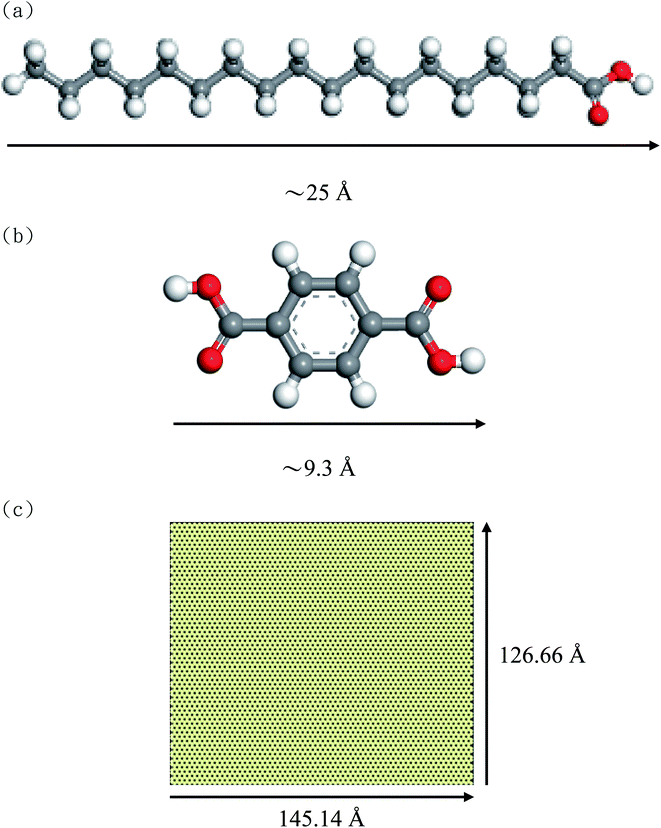 | ||
| Fig. 1 Molecular structures of (a) STA, (b) TPA, and (c) graphene with periodic boundary conditions in the x- and y-dimensions. | ||
To find the most stable STA buffer supramolecule on the graphene, the following sequential steps were taken: (1) firstly, the STA molecules were randomly imposed into the region above the graphene. (2) A virtual wall paralleled to the graphene, located above the highest STA molecule, was gradually moved toward the graphene to force all STA molecules to contact the graphene surface. The virtual wall had a weak repulsive interaction with all STA molecules. (3) The NVT MD simulation was conducted at 1500 K for 50 ps in order to produce a completely random STA distribution on the graphene. (4) Finally, the STUN-BH-DMD method19–23 was conducted to predict the most stable two-dimensional STA supramolecule on the graphene. The detailed STUN-BH-DMD process used for the current system can be found in the ESI.†
The large-scale atomic/molecular massively parallel simulator (LAMMPS) package24 was employed to conduct the STUN-BH-DMD search and MD simulation. All MD simulations using the most stable configurations after the STUN-BH-DMD method search considered the long-ranged coulombic interaction by the particle–particle particle–mesh (PPPM) method.18,25 The Open Visualization Tool (OVITO) package26 was used to visualize the simulation results and to do the post processing.
Results and discussion
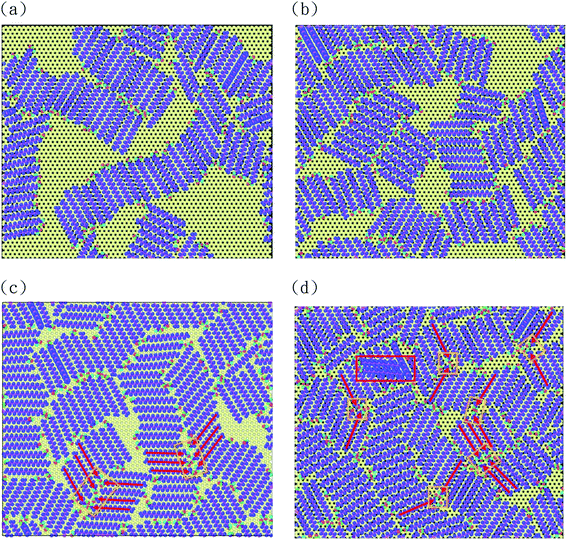
The experimental results of Lin's study10 show that the final supramolecular morphologies on the Cu(100) substrate significantly depend on the coverage of the supramolecule compositional molecule. Moreover, in Li's experimental study,16 they found the growth mechanisms of three-dimensional TPA thin films were different when the coverage of the STA buffer layer was different. They found that the mechanisms of phase separation growth and layer-by-layer (LBL) growth occur at lower and higher buffer layer coverages, respectively. Consequently, four STA coverages on the graphene were considered in this study, which used 100, 120, 140, and 145 STA chains on the graphene, with the surface area shown in Fig. 1(c). For convenience in presenting our simulation results, these four coverages are designated as STA100, STA120, STA140, and STA145.Fig. 2(a)–(d) shows the most stable configurations after the STUN-BH-DMD search for different STA coverages, and the corresponding average interaction strengths of STA–STA and STA–graphene as well as the average hydrogen bond number are listed in Table 1. For STA100, STA120, and STA140, one can see that all STA molecules are adsorbed by the graphene surfaces. For STA145, two STA molecules marked by the rectangle in Fig. 2(d) are on the first STA buffer layer, indicating that the STA145 is oversaturated in terms of forming a single buffer layer on the graphene surface. For the lower coverages (STA100 and STA120), there is more open space on the graphene for STA chains to adjust their orientations relative to their neighbor STA chains in order to reach the most stable configuration. Fig. 2(a) and (b) indicate that there are two main mechanisms causing the system to have the lower energy. The first one is the formation of hydrogen bonds between the terminal COOH groups of the two STA chains, and the second one is the stacking of STA chains by their long axis. At STA100 and STA120, the stacking mechanism is dominant and several domains are formed by the STA stacking, which can be seen in Fig. 2(a) and (b). At the higher STA coverages shown in Fig. 2(c) and (d), one can see most STA stacking piles are connected by the hydrogen bonds forming between the STA chains of neighbor piles. In Table 1, the average hydrogen bond numbers of STA140 and STA145 are higher than those of STA100 and STA120. The average STA interaction energies of STA140 and STA145 are also higher than those of STA100 and STA120, because the average hydrogen bond numbers in STA140 and STA 145 are higher. It should be noted that the interaction energy between the STA and the graphene is nearly the same for all coverages.
| Coverage | Average STA interaction energy with STA (kcal mol−1) | Average STA interaction energy with graphene (kcal mol−1) | Average of H-bond (per STA) |
|---|---|---|---|
| STA100 | −9.01 | −35.81 | 0.38 |
| STA120 | −9.08 | −35.80 | 0.51 |
| STA140 | −9.72 | −35.75 | 0.53 |
| STA145 | −10.07 | −35.17 | 0.65 |
In Fig. 2(c) and (d), one can see some local herringbone structures formed by the hydrogen-bonded STA pair, as indicated by the red arrows. In Rabe's study,27 the 1-octadecanol molecule with the same alkyl part as that of the STA molecule is used to form the supramolecule on the HOPG. Their experimental results show that the herringbone arrangements formed by a hydrogen-bonded 1-octadecanol pair exist, because the pairing of hydrogen bonds requires a tilt angle between two molecules to ensure the stability of the hydrogen bonds, thus forming a herringbone arrangement. Their experimental finding is confirmed by these simulation results presented in Fig. 2(c) and (d).
After the most stable STA structures were obtained by the STUN-BH-DMD method, their thermal properties were further investigated by MD simulations. Since STA145 is oversaturated on the graphene, only the cases of STA100, STA120, and STA140 were used for this MD study. The square displacement (SD) profile during the temperature elevation was used to observe the thermal stability of 2D STA supramolecules on graphene at different coverages. The definition of SD at time t is presented in eqn (1):
 | (1) |
Fig. 3 represents the square displacement (SD) profiles of STA100, STA120, and STA140 during the temperature elevation from 300 to 600 K. For each case, the SD profiles present the H-bond donor and acceptor atoms of all STA terminal COOH groups, as well as the alkane part of the STA molecule. One can see these SD profiles slightly increase with the temperature at the early elevation process up to 380 K, 400 K, and 470 K for STA100, STA120, and STA140, respectively. When the temperatures exceed these temperatures, the SD has a tendency to increase more significantly with the increasing temperature. This identifies the point at which STA buffers of different coverages begin to disintegrate, so these temperatures are designated as Td, the disintegration temperature. In Fig. 3(a)–(c), morphologies at temperatures 20 K lower and 20 K higher than the corresponding Td are shown as insets. Note that the morphologies at the temperatures 20 K lower than Td are very similar to the corresponding initial morphologies shown in Fig. 2. At Td, the morphologies of the STA buffer layers are slightly different from those at the lower temperatures, indicating that the kinetic energies at Td begin to overcome the STA binding energy. In contrast, when the temperatures exceed Td, the arrangements of STA chains (e.g., insets showing temperatures 20 K higher than Td) are considerably different from those shown in Fig. 2, implying that the STA buffer layers disintegrate when the system temperature exceeds Td. A comparison of these Td values shows that the Td value is higher at higher STA coverage. This is because the average STA bonding energy is higher at the higher STA coverage, as shown in Table 1. The SD profiles of the COOH group and the alkanes clearly show that the COOH and alkane profiles begin to separate in STA100 and STA120 when the system temperatures exceed Td, implying that the disintegrations in these two cases start from the breakage of hydrogen bonds. For STA140, the COOH and alkane SD profiles still closely match at temperatures lower than 570 K, which is about 100 K higher than its Td. This is likely due to the crowding of the STA molecules and therefore there is insufficient space to disintegrate.
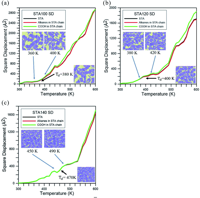 | ||
| Fig. 3 Square displacement (SD) profiles during the temperature elevation process for (a) STA100, (b) STA120, and (c) STA140. Td is used to indicate the disintegration temperature for each case. | ||
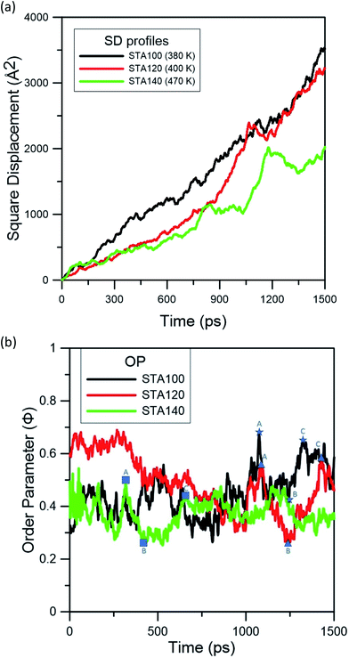
To investigate the STA disintegration processes, Fig. 4(a) and (b) show the SD profiles and the order parameter (OP) variations at the corresponding Td during the MD simulations, respectively. Fig. 4(a) shows the values of SD profiles increase with the simulation time, indicating that the STA molecules have left their equilibrium positions and can continually move on the graphene surface. In order to investigate the STA molecular arrangement change on the graphene surface at the system temperatures of Td, Fig. 4(b) shows the variations of OP during the MD simulation. The OP, P2, is expressed by the following formula:29
 | (2) |
cos![[thin space (1/6-em)]](https://www.rsc.org/images/entities/char_2009.gif) θ = u·n θ = u·n
| (3) |
 | (4) |
In Fig. 4(b), one can see the OP values of STA100, STA120, and STA140 range between 0.3 and 0.7 with significant fluctuations during the MD simulation. To observe the configuration change when the OP decreases from the local maximum to a local minimum and then increases to another local maximum, labels A (local maximum), B (local minimum), and C (local maximum) on the OP profiles for each case are demarcated by different symbols in Fig. 4(b), and the corresponding morphologies of STA100, STA120, and STA140 for labels A, B, and C are shown in Fig. 5.
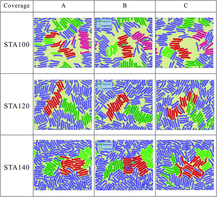 | ||
| Fig. 5 The corresponding STA morphologies on the graphene surface at labels A, B, and C indicated in OP profiles of Fig. 4(b) (see three coverages animation from A to C in the ESI.†). | ||
In Fig. 5, STA molecules marked in red for all STA coverages were used as the reference STA molecules for presenting the STA subdomains at label B. It can be seen the STA subdomains marked in green or dark-green at label B are perpendicular to the reference subdomain, resulting in lower OP values. At labels A and C, the STA molecules in these two subdomains seem not significantly perpendicular to each other, leading to the relatively higher OP values, as shown in Fig. 4(b). At the disintegration temperatures, one can see the STA molecules can move on the graphene surface to adjust their arrangement for making the STA layer more stable with a higher OP value (see Animation 1–3 in ESI†) However, ordered STA layers at Label A can only be maintained for a very short time because the kinetic energies at Td are high enough to disintegrate the ordered STA layer.
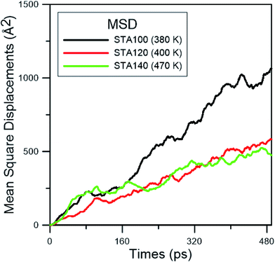
In order to study the diffusion behaviors of STA, the mean square displacement (MSD) profiles were obtained first. The MSD is calculated on the basis of eqn (5):
 | (5) |
 | (6) |
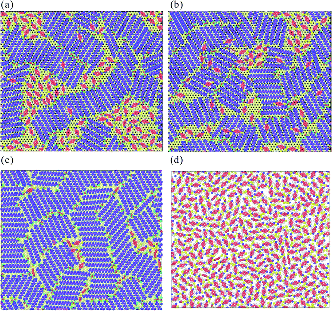 | ||
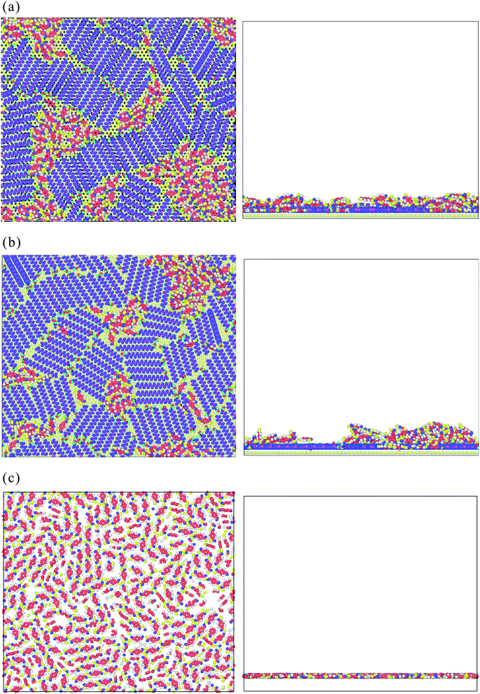
| Fig. 7 The early growth mechanism of the TPA supramolecule on (a) STA100, (b) STA120, (c) STA140, and (d) graphene. For clear observation on the TPA arrangement, the graphene structure is hidden. | ||
Fig. 8(a)–(c) show the top and side views of TPA/STA arrangement when more TPA molecules were adsorbed onto the STA buffer layer. For STA100 and STA120 shown in Fig. 8(a) and (b), after filling the holes with TPA molecules, the subsequent TPA molecules turn out to be adsorbed by the TPA molecules near or within the holes, resulting in the three-dimensional TPA growth. One can see the TPA/STA phase separation is still dominant for STA100 and STA120. In Fig. 8(c) for STA140, the subsequent TPA molecules finally form a complete TPA monolayer on the graphene, indicating that the layer by layer growth mechanism of TPA on the STA buffer layer results in high coverage.
For observing the local number density distribution of three-dimensional TPA supramolecular structures on the STA140 and graphene through the layer-by-layer growth mechanism, 2500 TPA molecules were placed on the established STA140 buffer layer and pristine graphene first. A virtual repulsive wall parallel to the graphene surface was also used to confine all molecules between the graphene surface and the virtual repulsive wall. The distance between the graphene surface and the virtual repulsive wall was adjusted until the average pressure was close to 1 atm during the NVT MD simulation at 300 K. Then, the NVT MD at 300 K was performed for another 4 ns to completely relax the system. The integration time step was 0.5 fs and the Nosé–Hoover thermostat was introduced to control the system temperature. A cut-off distance of 12 Å was utilized for calculate the 2 dimensional long-range electrostatics by Ewald summation and van der Waals interactions.
Fig. 9 shows the number density distribution of TPA molecules on the STA140 and pure graphene along the z dimension, respectively. It can be seen the first two density peaks of each case are relatively more distinct than other parts of the density profiles. For a certain range of z, the density value almost fluctuates with a constant value, which corresponds to the bulk TPA density. In Table 2, the order parameters of TPA molecules within the first, second peaks, and bulk region are listed. It should be noted that the reference vector is the direction normal to the graphene surface and the direction normal to the six-membered ring of the TPA molecule is used for the molecular reference vector. Consequently, if all TPA molecules are adsorbed completely flat on the substrate, the OP value is 1. For the pure graphene, the first density peak is the highest and the narrowest among all the density peaks. The corresponding OP of the first peak in Table 2 is about 0.81 and the density between the first and second peak is close to 0, indicating that most TPA molecules within the first peak were adsorbed completely flat on the graphene surface with the 2-dimensional hydrogen bonding network. For the second layer of the pure graphene case, the OP becomes lower, implying that the TPA molecules within the second peak can form the three-dimensional hydrogen bonding network with TPA molecules above the second TPA layer. For the STA140 case, the OP values of the first and second peaks are lower than the corresponding peaks of the pure graphene case and the density between the first and second peaks are not close to zero, indicating that the TPA supramolecules on STA140 are formed by the three dimensional hydrogen bond network through the LBL mechanism.
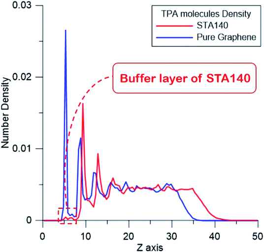 | ||
| Fig. 9 The number density distribution of TPA molecules on STA140 and pure graphene along the thickness direction. | ||
| 1st peak | 2nd peak | Bulk region | |
|---|---|---|---|
| STA140 | 0.57 | 0.22 | 0.04 |
| Pure graphene | 0.81 | 0.42 | 0.06 |
Conclusions
The STUN-BH-DMD method with the Dreiding force field has been used to find the most stable STA supramolecular structures on the graphene and TPA supramolecular structures on the STA buffer layer. Two major TPA growth mechanisms, phase separation and LBL growth, are observed. According to the simulation results, the following conclusions can be made:(1) The STA molecule arrangement on the graphene depends on the STA coverage. At the relatively lower coverages, STA100 and STA120, the stacking of STA molecules by their long axis is the main mechanism to stabilize the STA buffer layer. At the higher STA coverage, STA140, the hydrogen bonding between the terminal COOH groups of two STA molecules makes the STA buffer layer more stable than those at the lower STA coverages.
(2) The disintegration temperature of STA140 is higher than those of STA100 and STA120 after the thermal stability simulation by the temperature elevation process. It is because the average hydrogen bond number of STA140 is the highest.
(3) At the early growth stage of the TPA supramolecule on the STA buffers, the TPA molecules were first adsorbed by the holes formed between the STA piles on the graphene. At the lower STA coverages, STA100 and STA120, the subsequent TPA molecules were adsorbed by the TPA molecules within the holes, resulting in the phase separation growth.
(4) At the higher coverage STA140 or on the pure graphene, the TPA supramolecule tends to grow in all three dimensions by the LBL mechanism.
In this study, a general process using the STUN-BH-DMD method was developed to predict the TPA supramolecular structure on the STA buffer layer or on the graphene. The same numerical process can be further used to predict the arrangement of any other molecule type on a surface with different textures. For the STUN-BH-DMD search process, the final configurations of STA100, STA120, and STA140 were obtained by the quenching process from 1100 to 300 K with a cooling rate of 0.008 K per STUN-BH-DMD iteration. A much slower cooling rate than the current one obtains very similar configurations to those presented in the current study. Consequently, the STA molecules completely arranged in parallel (molecular axis of each STA aligns along the same direction) are not as stable as those forming subdomains according to the current simulation results.
Conflicts of interest
There are no conflicts to declare.Acknowledgements
The authors would like to thank the (1) Ministry of Science and Technology of Taiwan, under Grant No. MOST 105-2221-E-110-030-MY3; (2) CMRPG8I0341 from Chang Gung Memorial Hospital for their support on this study.References
- M. Canas-Ventura, et al., Coexistence of one-and two-dimensional supramolecular assemblies of terephthalic acid on Pd (111) due to self-limiting deprotonation, J. Chem. Phys., 2006, 125(18), 184710 CrossRef CAS PubMed.
- A. G. Slater, P. H. Beton and N. R. Champness, Two-dimensional supramolecular chemistry on surfaces, Chem. Sci., 2011, 2(8), 1440–1448 RSC.
- J. van der Lit, et al., Modeling the self-assembly of organic molecules in 2D molecular layers with different structures, J. Phys. Chem. C, 2015, 120(1), 318–323 CrossRef.
- K. Ariga, Y. M. Lvov, K. Kawakami, Q. Ji and J. P. Hill, Layer-by-layer self-assembled shells for drug delivery, Adv. Drug Delivery Rev., 2011, 63(9), 762–771 CrossRef CAS PubMed.
- R. Haag, Supramolecular drug-delivery systems based on polymeric core–shell architectures, Angew. Chem., Int. Ed., 2004, 43(3), 278–282 CrossRef CAS PubMed.
- Y. Chen, C. Tan, H. Zhang and L. Wang, Two-dimensional graphene analogues for biomedical applications, Chem. Soc. Rev., 2015, 44(9), 2681–2701 RSC.
- Y. Zhao, Q. Wu, Q. Chen and J. Wang, Molecular Self-Assembly on Two-Dimensional Atomic Crystals: Insights from Molecular Dynamics Simulations, J. Phys. Chem. Lett., 2015, 6(22), 4518–4524 CrossRef CAS PubMed.
- B. Xu, S. Yin, C. Wang, X. Qiu, Q. Zeng and C. Bai, Stabilization effect of alkane buffer layer on formation of nanometer-sized metal phthalocyanine domains, J. Phys. Chem. B, 2000, 104(45), 10502–10505 CrossRef CAS.
- V. V. Korolkov, M. Baldoni, K. Watanabe, T. Taniguchi, E. Besley and P. H. Beton, Supramolecular heterostructures formed by sequential epitaxial deposition of two-dimensional hydrogen-bonded arrays, Nat. Chem., 2017, 9(12), 1191 CrossRef CAS PubMed.
- F. Vidal, E. Delvigne, S. Stepanow, N. Lin, J. V. Barth and K. Kern, Chiral phase transition in two-dimensional supramolecular assemblies of prochiral molecules, J. Am. Chem. Soc., 2005, 127(28), 10101–10106 CrossRef CAS PubMed.
- F. Tao and S. L. Bernasek, Chirality in supramolecular self-assembled monolayers of achiral molecules on graphite: Formation of enantiomorphous domains from arachidic anhydride, J. Phys. Chem. B, 2005, 109(13), 6233–6238 CrossRef CAS PubMed.
- T. Suzuki, et al., Substrate effect on supramolecular self-assembly: from semiconductors to metals, Phys. Chem. Chem. Phys., 2009, 11(30), 6498–6504 RSC.
- N. Martsinovich and A. Troisi, Modeling the Self-Assembly of Benzenedicarboxylic Acids Using Monte Carlo and Molecular Dynamics Simulations, J. Phys. Chem. C, 2010, 114(10), 4376–4388 CrossRef CAS.
- H. Zhao, et al., Self-assembly of hydrogen-bonded supramolecular complexes of nucleic-acid-base and fatty-acid at the liquid–solid interface, Phys. Chem. Chem. Phys., 2016, 18(21), 14168–14171 RSC.
- F. Tao and S. L. Bernasek, Self-assembly of 5-octadecyloxyisophthalic acid and its coadsorption with terephthalic acid, Surf. Sci., 2007, 601(10), 2284–2290 CrossRef CAS.
- Y. Li, et al., Building layer-by-layer 3D supramolecular nanostructures at the terephthalic acid/stearic acid interface, Chem. Commun., 2011, 47(32), 9155–9157 RSC.
- R. Hentschke, B. L. Schürmann and J. P. Rabe, Molecular dynamics simulations of ordered alkane chains physisorbed on graphite, J. Chem. Phys., 1992, 96(8), 6213–6221 CrossRef CAS.
- S. L. Mayo, B. D. Olafson and W. A. Goddard, DREIDING: a generic force field for molecular simulations, J. Phys. Chem., 1990, 94(26), 8897–8909 CrossRef CAS.
- H.-W. Yang, S.-P. Ju, C.-H. Cheng, Y.-T. Chen, Y.-S. Lin and S.-T. Pang, Aptasensor designed via the stochastic tunneling-basin hopping method for biosensing of vascular endothelial growth factor, Biosens. Bioelectron., 2018, 119, 25–33 CrossRef CAS PubMed.
- N. V. Dokholyan, S. V. Buldyrev, H. E. Stanley and E. I. Shakhnovich, Discrete molecular dynamics studies of the folding of a protein-like model, Fold. Des., 1998, 3(6), 577–587 CrossRef CAS PubMed.
- F. Ding, D. Tsao, H. Nie and N. V. Dokholyan, Ab initio folding of proteins with all-atom discrete molecular dynamics, Structure, 2008, 16(7), 1010–1018 CrossRef CAS PubMed.
- K. Hamacher and W. Wenzel, Scaling behavior of stochastic minimization algorithms in a perfect funnel landscape, Phys. Rev. E: Stat., Nonlinear, Soft Matter Phys., 1999, 59(1), 938 CrossRef CAS.
- W. Wenzel and K. Hamacher, Stochastic tunneling approach for global minimization of complex potential energy landscapes, Phys. Rev. Lett., 1999, 82(15), 3003 CrossRef CAS.
- S. Plimpton, Fast parallel algorithms for short-range molecular dynamics, J. Comput. Phys., 1995, 117(1), 1–19 CrossRef CAS.
- C. Li and A. Strachan, Molecular simulations of crosslinking process of thermosetting polymers, Polymer, 2010, 51(25), 6058–6070 CrossRef CAS.
- A. Stukowski, Visualization and analysis of atomistic simulation data with OVITO–the Open Visualization Tool, Modell. Simul. Mater. Sci. Eng., 2009, 18(1), 015012 CrossRef.
- J. P. Rabe and S. Buchholz, Commensurability and Mobility in Two-Dimensional Molecular Patterns on Graphite, Science, 1991, 253(5018), 424 CrossRef CAS PubMed.
- U. Essmann, L. Perera, M. L. Berkowitz, T. Darden, H. Lee and L. G. Pedersen, A smooth particle mesh Ewald method, J. Chem. Phys., 1995, 103(19), 8577–8593 CrossRef CAS.
- O. Berger, O. Edholm and F. Jähnig, Molecular dynamics simulations of a fluid bilayer of dipalmitoylphosphatidylcholine at full hydration, constant pressure, and constant temperature, Biophys. J., 1997, 72(5), 2002–2013 CrossRef CAS PubMed.
- C. J. Slevin and P. R. Unwin, Lateral proton diffusion rates along stearic acid monolayers, J. Am. Chem. Soc., 2000, 122(11), 2597–2602 CrossRef CAS.
Footnotes |
| † Electronic supplementary information (ESI) available. See DOI: 10.1039/c9ra07007a |
| ‡ Both authors contributed equally to this work. |
| This journal is © The Royal Society of Chemistry 2020 |

