DOI:
10.1039/C9RA06568G
(Paper)
RSC Adv., 2020,
10, 29-42
Disposal of high-arsenic waste acid by the stepwise formation of gypsum and scorodite
Received
21st August 2019
, Accepted 2nd December 2019
First published on 23rd December 2019
Abstract
The typical disposal of high-arsenic waste acid is at the expense of discharging a large quantity of hazardous solid waste, resulting in secondary pollution of arsenic. We propose a modified lime/ferric salt method for high-arsenic waste acid disposal by the stepwise formation of gypsum and scorodite at atmospheric pressure. The sulfuric acid in the high-arsenic waste acid is first removed by calcium carbonate generating gypsum, and then the arsenic in the solution is precipitated in form of scorodite. Gypsum with an arsenic leaching concentration below 5 mg L−1 is obtained at a final pH of 0.5 in the calcium carbonate neutralization stage. In the second stage, the optimal conditions including a starting pH of 2.0, an Fe/As ratio of 1.5, a reaction temperature in the range of 80–90 °C and a reaction time equal to or longer than 8 hours provide an arsenic removal efficiency of 95.34% by the formation of well-crystallized and environmentally stable scorodite with grain sizes in a range of 1–5 μm. The proposed process offers a promising and facile solution for the low-cost disposal of high-arsenic waste acid in the nonferrous metallurgical industry, which enables an efficient arsenic removal with the good accessibility of chemical reagents and facilities.
1. Introduction
Arsenic is a major contaminant or impurity discharged during the extraction of heavy non-ferrous metals from minerals that are usually associated with arsenic. Arsenic with different valence states (+3, +5, and −3) can exist in the forms of arsenic acid, arsenic-compound salt, arsenic-bearing sulfide and arsenic oxide with different mobility in nature.1 The arsenic compounds were mainly formed naturally, including arsenopyrite, orpiment, realgar pyrite, galena and chalcopyrite.2 The huge and increasing emission of arsenic in the exploitation of arsenic-contained minerals, typically heavy non-ferrous metals including Cu, Pb, Zn, Ni, Sn etc., is far greater than the recent market. China is the largest arsenic discharge country because of the large-scale nonferrous metallurgical industry. 100![[thin space (1/6-em)]](https://www.rsc.org/images/entities/char_2009.gif) 000 tons of arsenic per year is introduced into the smelting process from nonferrous concentrates generating an amount of arsenic solid waste. Among these, about 50% of arsenic is stabilized in slag. 8–23% of arsenic is removed through the dust removal system and anode mud in the electrolysis process, which might be recycled or disposed. However, the most hazardous and worthless arsenic in form of high-arsenic waste acid still accounts for 16% of the total arsenic emission. The arsenic concentrations for the waste acid usually range from 0.5 to 30 g L−1 with sulfuric acid concentrations ranged from 10 to 200 g L−1, which is the most crucial arsenic waste because of its high arsenic mobility and toxicity.3–5 Even a slight leakage of high-arsenic waste acid will cause serious arsenic pollution as well as widely safety and environmental concern.6,7
000 tons of arsenic per year is introduced into the smelting process from nonferrous concentrates generating an amount of arsenic solid waste. Among these, about 50% of arsenic is stabilized in slag. 8–23% of arsenic is removed through the dust removal system and anode mud in the electrolysis process, which might be recycled or disposed. However, the most hazardous and worthless arsenic in form of high-arsenic waste acid still accounts for 16% of the total arsenic emission. The arsenic concentrations for the waste acid usually range from 0.5 to 30 g L−1 with sulfuric acid concentrations ranged from 10 to 200 g L−1, which is the most crucial arsenic waste because of its high arsenic mobility and toxicity.3–5 Even a slight leakage of high-arsenic waste acid will cause serious arsenic pollution as well as widely safety and environmental concern.6,7
Neutralization and sulfurization processes are typical processes to treat the high-arsenic waste acid.1,3 In neutralization process, arsenic in the waste acid is transformed into solid hazardous waste composed of calcium arsenate/arsenite, gypsum and other compounds by using Ca-containing compounds (CaO, Ca(OH)2 and CaCO3) as precipitators.8 When sulfides (Na2S and H2S) are used to precipitate the arsenic to produce arsenic sulfide, a large quantity of hazardous arsenic sulfide sludge will be discharged. For those two technologies, arsenic is partially fixed in the solid hazardous waste. Although the mobility of arsenic is largely reduced in solid wastes, the high risk of arsenic pollution remains for a disposal site of solid hazardous waste and secondary pollution from these solid arsenic waste is unavoidable during the transportation and storage.9 In addition, the further harmless disposal for those arsenic-bearing hazardous waste is extremely expensive. New technology for arsenic fixing is urgently desiderated. Arsenic fixation technology includes physical encapsulation and chemical fixation. The former is not suitable for treatment of the liquid arsenic waste.10 The transformation of As(III) and As(V) into arsenic minerals with low solubility and high stability is a feasible technology for high-arsenic waste acid treatment.1 The Ca- and Fe-associated compounds are the main minerals for arsenic immobilization.11 The formation of calcium arsenate in a Ca(II)–As(V)–H2O system could obviously decrease the arsenic mobility.12–15 But it remains unstable because of extremely high solubility in acid condition or exposed to CO2. Crystalline and amorphous arsenate ferric compound with high arsenic can be formed in the Fe–As(V)–H2O system at pHs ranged from 1 to 3.1,16–20 Among them, scorodite (FeAsO4·2H2O) shows a high stability,21,22 a high theoretical arsenic content of up to 32%,23 a less volume of slag and it is easy to separate from the solid–liquid mixture. Scorodite is stable in the mildly acidic environment, while in a neutral to weakly alkaline environment, it can easily decompose and release As into solutions. Its stability can be intensified when scorodite was encapsulated by polyferric sulfate24,25 and aluminum silicate gel,26 etc. The synthesis can be modified by using a catalyst or additives.27,28 Owing to the above properties, scorodite is recognized as the best arsenic-stabilization mineral and attracts widely attentions.16,17,29–42
The synthesis of scorodite is of great importance for arsenic removal rate from a arsenic-bearing solution.6,35 The hydrothermal method was proposed using Fe(III) and As(V) starting solution at temperatures higher than 125 °C in the pHs range of 0.2–1.8 to synthesize scorodite.43 Afterwards, atmospheric synthesis method was carried out to produce crystalline scorodite from Fe(III) and As(V) solution in the temperature range from 80 to 95 °C by means of controlling supersaturating.29,30,43–47 The hydrothermal reaction chemistry and characterization of ferric arsenate precipitated from Fe2(SO4)3–As2O5–H2SO4 solutions in the temperature range of 150–225 °C were studied.18 A synthesis map of arsenate phases in Fe(II)–AsO43−–SO42− system was proposed and releasing behavior was also reported. To improve the feasibility in the application, an atmospheric scorodite synthesis process was studied under 95 °C ventilation with oxygen or air oxidation of Fe(II) in the presence of As(V) by Fujita.35,45,47 The well-crystallized and environmentally friendly scorodite were obtained through a low-degree supersaturation precipitation procedure. Further studies have shown that the addition of zinc, copper, sodium and strontium ions would affect the redox potential of solution but not alter the composition and structure of the scorodite.39,46 Application of this atmospheric synthesis method to fix arsenic in anode mud and wastewater with high-arsenic concentration in form of scorodite was proved to be feasible.24,38,48 On the basis of Fujita's method, ultrasonic was introduced to the atmospheric synthesis method to produce high-crystallinity scorodite with large particle size (>10 μm).49 An As(III)-bearing copper refinery process solution was also treated by biomineralization of scorodite.50 Therefore, the scorodite method for the arsenic fixing and treatment of high-arsenic waste acid might be a green process.
In the present work, a modified process is proposed to dispose the high-arsenic copper smelting waste acid through the stepwise formation of gypsum and scorodite. The first stage (Stage-I) of this process is to remove sulfuric acid in high-arsenic waste acid by calcium carbonate. The pH value of residual solution would increase to suitable rang for scorodite synthesis after Stage-I. In the second stage (Stage-II), an atmospheric synthesis method is used to remove arsenic by the formation of scorodite using arsenic-bearing solution obtained from the Stage-I after oxidation by H2O2. Most arsenic in waste acid can be removed in the form of scorodite in Stage-II. A conventional lime/ferric salt method could be used to treat filtrate-II from Stage-II to produce clean water in Stage-III. Theoretically, solid sludge produced from Stage-III can be identified as a kind of general industrial solid waste due to the low concentrations of contaminants. Besides, gypsum produced in Stage-I and scorodite precipitated in Stage-II are classified as a general industrial solid wastes due to their low leaching toxicities. Moreover, facilities (reactors and liquid–solid separations) and raw material essential for this process are the same with the a conventional neutralization method,3,51 which will greatly enhance its economy and practicability. The treatment parameters in first two stages are optimized to obtain high arsenic removal efficiency and environmentally friendly precipitates (scorodite and gypsum). The relationship between structure of precipitates and reaction conditions are explored. The performance of this process is also evaluated in a continuous experiment on the basis of optimal parameters.
2. Materials and methods
2.1. High-arsenic waste acid and reference materials
High-arsenic waste acid, a hazardous acid wastewater, is mainly produced by heavy nonferrous (Cu, Pb, Zn, Ni, and Sn, etc.) smelting plant. The high-arsenic waste acid used in this study was obtained from a copper smelting plant equipped with Isa furnace in southwest China. It was produced from the water-washing purification of flue gas from the smelting of copper concentrate after filtrated by dust removal system. The high-arsenic waste acid contains a massive arsenic and a small quantity of Zn, Cu, Pb, Sb, and Cd, as shown in Table 1. The concentrations of H2SO4 and As are 76.56 and 24.50 g L−1, respectively. Analytical grade reagents were used for all reactions process. Chemicals reagents including H2O2, CaCO3, FeSO4·7H2O, H2SO4 and NaOH were purchased from the Sinopharm Group Chemical Reagent Co., Ltd.
Table 1 The chemical compositions of high-arsenic waste acid
| Element |
H2SO4 |
As |
Cu |
Zn |
Sb |
Pb |
Cd |
| Content (g L−1) |
76.56 |
24.50 |
0.16 |
3.81 |
0.17 |
6.99 × 10⁻³ |
0.98 |
2.2. Treatment of high-arsenic waste acid
The treatments of high-arsenic waste acid are composed of three stages including calcium carbonate neutralization (Stage-I), scorodite synthesis (Stage-II) and high-efficiency purification (Stage-III), as shown in Fig. 1. A mass of sulfuric acid is neutralize using calcium carbonate as a neutralization reagent through the formation of gypsum in Stage-I, as expressed in eqn (1). The pH value of the solution in Stage-I is controlled as high as possible to ensure the removal of the most sulfuric acid and minimum amount of precipitated arsenic. The As(III) in the Filtrate-I was oxidized through H2O2. The most arsenic was removed through formation of scorodite precipitate in Stage-II (eqn (2)). The filtrate liquid from the second stage is then submitted to a high-efficiency purification process to obtain clean water.| | |
CaCO3 + H2SO4 → CaSO4·2H2O↓+ CO2↑
| (1) |
| | |
Fe2(SO4)3 + 2H3AsO4 → 2FeAsO4↓ + 3H2SO4
| (2) |
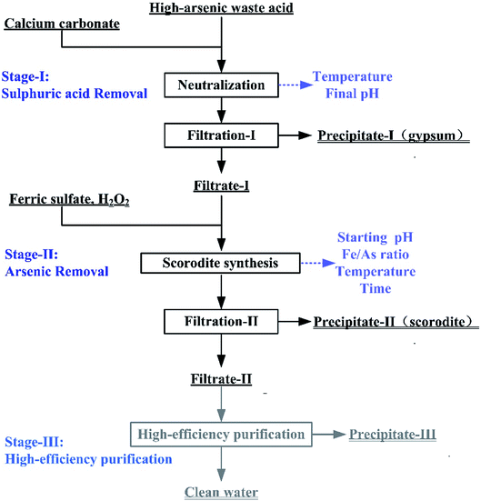 |
| | Fig. 1 The flow chart of the high-arsenic waste acid treatment. | |
The Stage-I and Stage-II in this process were optimized in a bench-scale experiment. In the Stage-I, CaCO3 was slowly added into the waste acid to reach a specific final pH at the temperatures ranged from 25 to 95 °C. The precipitate filtered from the liquid–solid mixture produced in the first stage was washed by isometric deionized water. The gypsum would be washed by deionized water at a 1.2:1 of liquid–solid rate. The gypsum is subjected to a toxic leaching test after the rinsed. When arsenic concentration in the leaching solution is less than 5 mg L−1, gypsum was classified as general solid waste. The washing-water was then added into Filtrate-I in order to avoid secondary arsenic emission. In this neutralization reaction, the influence of reaction temperature and final pH were studied. In the Stage-II, the As(V)-bearing filtrate and FeSO4·7H2O solution were mixed in a round-bottom three-neck flask. The temperature of three-neck flask was controlled by an electric heating insulation sleeve. The pH of the mixed solution was adjusted to the pre-set value by adding a small amount of NaOH solution. The influences of initial pH, Fe/As molar ratio, reaction temperature and reaction time were investigated in the scorodite synthesis. The precipitate was also washed with deionized water. The precipitates were submitted to leaching tests and physicochemical analysis. In the high-efficiency purification (Stage-III), CaO was added to the filtrate from the Stage-II treatment and adjusted the solution initial pH to 9–12 for 2 hours. The chemical composition of the solution was analyzed by ICP-OES and chemical titration method in all experiments. The test conditions of Stage-I, Stage-II, and Stage-III were summarized in Table 2.
Table 2 The test conditions of Stage-I, Stage-II, and Stage-III
| Stage |
Reagent |
Dosage kg m−3 |
Fe/As moral rate |
Reaction temperature/°C |
Time/h |
Initial pH |
Final pH |
| I |
CaCO3 |
39.69–44.63 |
— |
55–95 |
— |
— |
0.1–3 |
| II |
FeSO4·7H2O |
43.5–87 |
1.0–2.0 |
50–90 |
6–12 |
1–6 |
— |
| III |
CaO |
30.68–47.4 |
— |
— |
2 |
9–12 |
— |
2.3. Analytical methods
The liquid samples filtrated by a 0.2 μm cartridge filter were detected by an ICP-OES spectrometer (Analytik Jena AG) to determine concentrations of As, Fe and other metals. The solid precipitates were collected after the experiment by filtration and vacuum drying at 60 °C for the leaching test. The H2SO4 concentration in the solution was tested by chemical titration method. The pH of the solution was monitor by a digital pH meter (Hangzhou Ying Ao Instrument Co., Ltd.).
2.4. Characterization of the solids
The XRD datas of samples were collected on a Rigaku D/max-IIIB X-ray diffractometer at a scanning rate of 2° min−1 with 2θ ranged from 10° to 90° (Cu Kα radiation λ = 0.15406 nm). The morphology of samples was observed by SEM on a FEI Nova Nano SEM instrument using an accelerating voltage of 15 kV. An EDAX TEAM EDS (EDAX Mahwah-USA) equipped with a Silicon Drift Detector (SDD) was used to determine the chemical element compositions of the samples. The Fourier transform infrared spectrometer (FTIR) experiment was performed on a Bruker Tensor 27 in the scanning range of 4000–400 cm−1.
2.5. Leaching test
The leaching tests were carried out based on the United States standard of EPA Test Method 1311-TCLP.52 Since the leaching toxicity of As is the main harmful element which exceeds the limit value in TCLP, and it is the only one taken account in the following experiments. A weight of 5 g sample was added into a 100 mL of Teflon beaker and then adjusted with acetic acid to pH = 2.88 ± 0.05 at a liquid–solid ratio of 20:1. The Teflon beakers were placed on the WIGGENSWS20 in a rotation rate of 180 rpm for 18 hours. After extraction, the liquid extract was separated from the solid phase by filtration. The leaching solution was determined by a Plasma Quant PQ 9000 ICP-OES spectrometer (Analytik Jena AG).
3. Results and discussion
3.1. Calcium carbonate neutralization
In the Stage-I, the influence of neutralization temperature on the crystallization of gypsum was studied. The final pHs were also optimized to obtain a maximal removal rate of sulfuric acid and minimal residual arsenic in gypsum. Calcium carbonate is a common low-cost neutralization reagent used in acid water treatment processes,4 which can be also substituted for limestone in an industrial application.
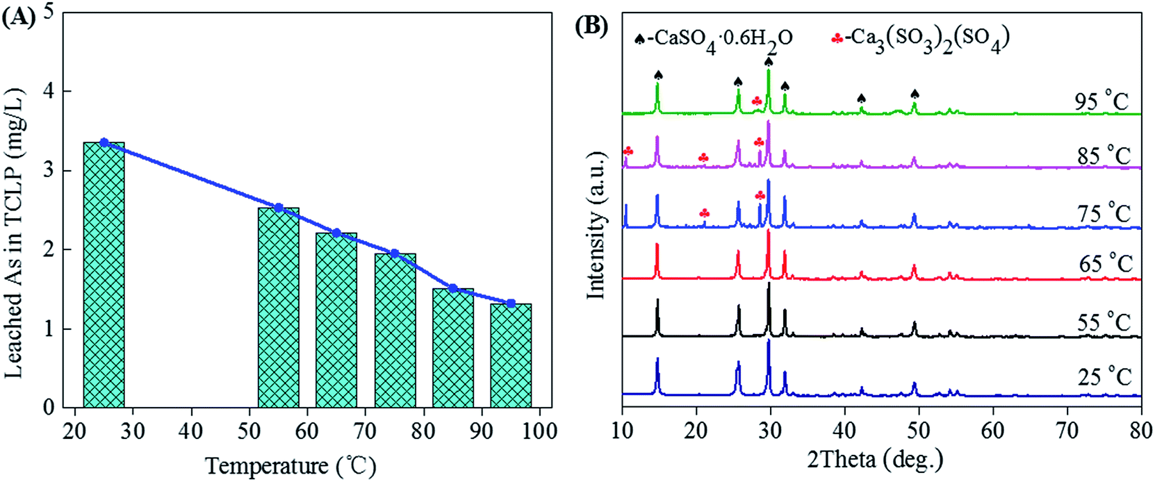
3.1.1 Effect of temperature. Fig. 2 shows the leached As in TCLP (A) and XRD patterns (B) of gypsums obtained from neutralization of high-arsenic waste acid at different temperatures. The waste acid with a sulfuric acid concentration of 76.56 g L−1 was adjusted to a final pH of 0.1 by continuous adding calcium carbonate.53 From the XRD patterns, the CaSO4·0.6H2O (gypsum) remains the main phase in precipitates due to neutralization reaction (Fig. 2B). For this strong exothermic reaction, the mixture of the waste acid with calcium carbonate was heated to the temperature around 50 °C in the first several minutes and the actual reaction temperature was fixed in the range of 55–95 °C. The weak Ca3(SO3)2(SO4) characteristic peaks reveal when the neutralization temperature increases to 75 °C. No other arsenic compounds and other impurities were observed in precipitates. The TCLP results tested according to EPA Test Method 1311 show that the arsenic leaching concentrations are in the ranges of 1.32 to 3.35 mg L−1, which is lower than the limit value (5 mg L−1) of arsenic leaching toxicity for the hazardous waste identification. It means the precipitation of arsenic can be avoided in the solution with a pH of 0.1. The As leaching concentration decreases with the increase of neutralization temperature, as shown in Fig. 2A. With the increase of reaction temperature, the half-peak breadth of the XRD of the gypsum increased, indicating the high temperature is beneficial of the formation of the large-grain gypsum. Gypsum with larger grain could reduce the amount of absorbed arsenic in the surface, leading to the decrease of As leaching concentration. Temperatures range from 25 to 65 °C is available for the production of environmentally friendly gypsum from neutralization at the final pH of 0.1. The gypsum hydrates are classified as solid wastes, which are safely disposed.
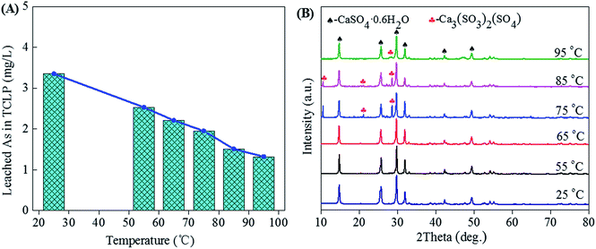 |
| | Fig. 2 The leached As concentration in TCLP (A) and XRD patterns (B) of gypsums obtained from neutralization (final pH = 0.1) of high-arsenic waste acid using calcium carbonate at temperatures ranged from 25 to 95 °C. | |
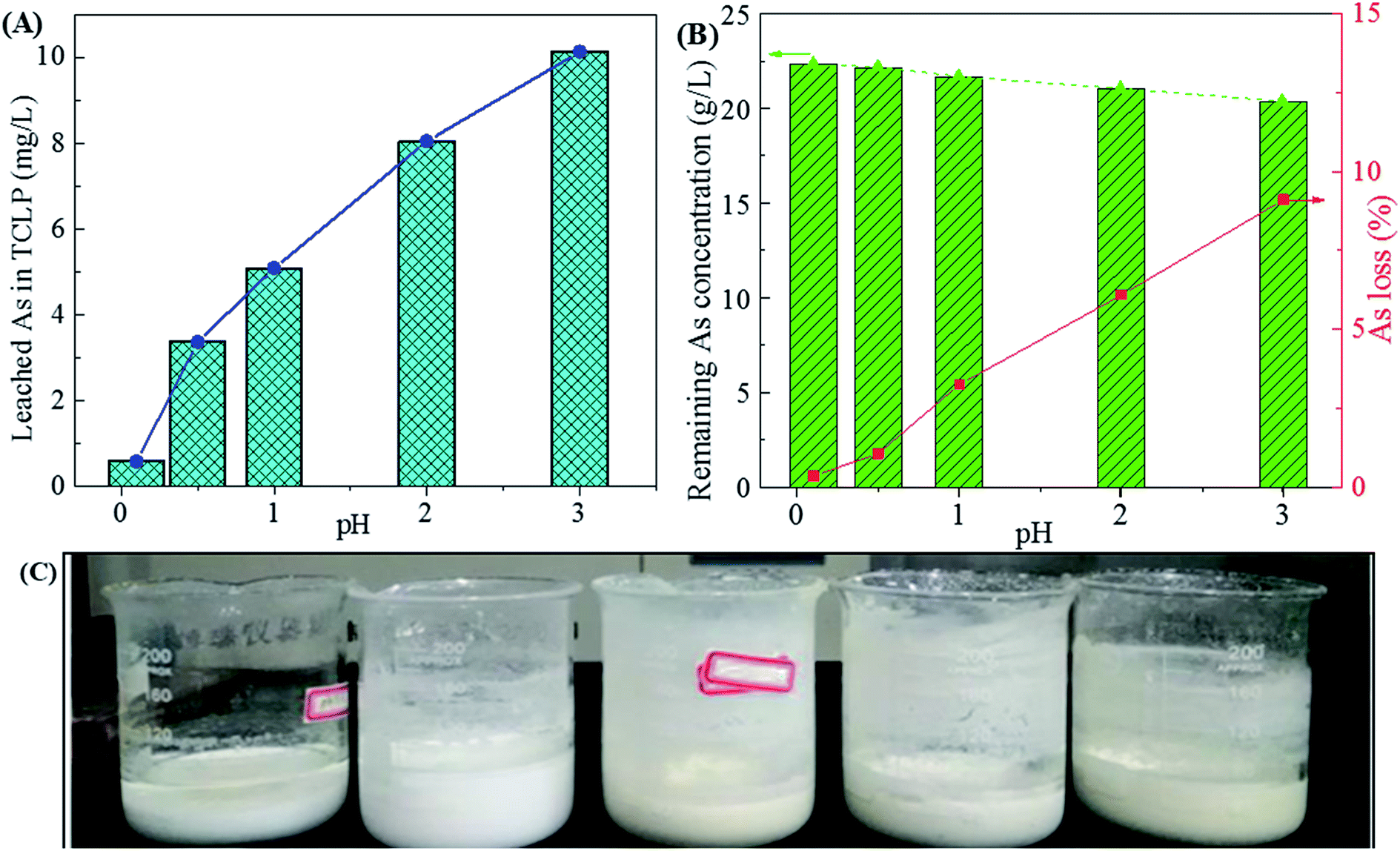
3.1.2 Effect of final pH. The final pH could regulate the removal efficiency of sulfuric acid in waste acid and leaching toxicity of gypsum. Fig. 3 shows the influence of final pH on the phase of gypsum, leaching toxicity and arsenic variation in the filtrates. In Fig. 3A, the As leaching concentration in TCLP increases with the increase of the final pH value. This may be due to arsenic be incorporated into gypsum through arsenic substituted for SO42− in the precipitate. Meanwhile, the gypsums become grey at higher pH values due to the co-precipitation of other heavy metals (Cu, Zn, Sb, Pb, Cd, et al.). The arsenic solubility is very high due to the formation of H3AsO4 and H3AsO3 in the acid solution while it decreases with the increase of pHs value. During the neutralization, arsenate and arsenite in the waste acid were prone to precipitated by Ca2+ with the increase of final pH.13,54 Those arsenic compounds were mixed with gypsum, resulting in the increase of arsenic leaching concentration for gypsum and a decrease of arsenic concentration in waste acid (Fig. 3B). Especially when the final pH reaches 1.0, the arsenic leaching concentration of gypsum is high up to 42.05 mg L−1 and the As loss reaches 3.26%. Most arsenic was remained in waste acid and low arsenic leaching concentrations of gypsums below 5 mg L−1 were obtained at the final pH values of 0.1 and 0.5 (2.59 and 4.93 mg L−1 for pH of 0.1 and 0.5, respectively). Taken the leaching toxicity of gypsum and arsenic loss of residual liquid into consideration for Stage-I, a final pH of 0.5 (15.48 g L−1 for sulfuric acid) is suitable for the calcium carbonate neutralization at 25 °C. An arsenic leaching concentration of 2.59 mg L−1 was obtained for the environmentally friendly gypsum, which is lower than the regularly limit in TCLP. Nearly 80% of sulfuric acid was removed by the formation of gypsum at a final pH of 0.5. Most arsenic was kept in the residual liquid (Filtrate-I) due to the low As loss (1.07%). The harmless and well-crystallized gypsum hydrate in forms of white homogeneous powders (Fig. 3C) was obtained.
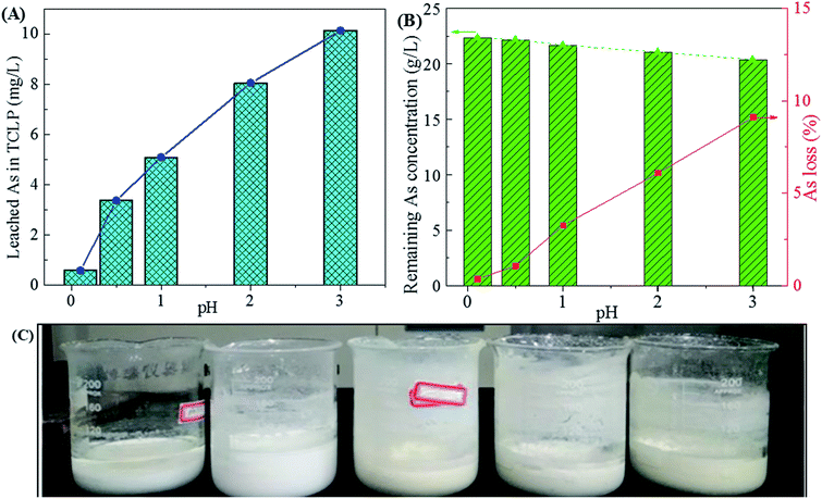 |
| | Fig. 3 The leached As concentration of gypsums in the TCLP (A), remaining As concentration in residual liquid (B) and photos of filtrates and gypsums (C) obtained from neutralization of high-arsenic waste acid using calcium carbonate at 25 °C as a function of final pH value. | |
3.2. Scorodite synthesis
In the Stage-II for scorodite synthesis, the influence of initial pH, Fe/As molar ratio, reaction temperature and reaction time on the crystallization of scorodite-associated materials were optimized to enhance the removal efficiency of arsenic. The arsenic-bearing residual liquid (Filtrate-I) after neutralization (at 25 °C with a final pH of 0.5) was submitted to investigate the precipitation behavior of scorodite. Before the experiment, the As(III) in Filtrate-I was oxidized to As(V) through addition of 20% stoichiometric excess H2O2 was added to waste acid.34
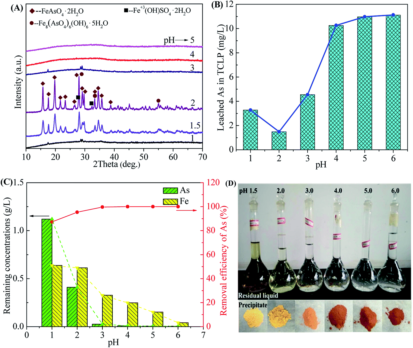
3.2.1 Effect of initial pH. The initial pH is significantly important for the formation of scorodite because it affects the mineralogy and arsenic mobility of the arsenic precipitate.35 The role of pH in the scorodite synthesis was investigated at 90 °C using a Fe/As ratio of 1.5 at initial pH values ranged from 1.0 to 6.0.Fig. 4 shows the phase transformation of precipitates, leaching toxicity variation and changes of filtrate composition as a function of initial pHs value. The XRD patterns in Fig. 4A indicate that well-crystallized scorodite was formed in the precipitates obtained at the pHs values of 1.5 or 2.0.35 The characteristic peaks of scorodite take the majority of strong diffraction peaks, indicating that scorodite is the main component in the precipitate. The weak peaks corresponding to tooeleite (basic ferric arsenate, Fe8(AsO4)6(OH)6·5H2O),5,55 butlerite (Fe3+(OH)SO4·2H2O) and rozenite (Fe2+SO4·4H2O) were also detected due to precipitation of excess Fe3+ and SO42− ions. Some weak characteristic peaks of scorodite also appear in the precipitates corresponding to the pH values of 1.0 and 3.0 due to the formation of crystalline scorodite in the amorphous As-immobilized species. The strong XRD peaks of the sample obtained at the pH of 2.0 indicates a higher crystallinity for scorodite. The pH ranges (1.0–3.0) are available for scorodite synthesis, which is wider than that of reported by previous researches.47 According to the Eh–pH diagram of Fe–As–H2O system,56 FeAsO4 (ferric arsenate or scorodite) phases are available at a pH range of 0–4.5. Scorodite is inclined to re-dissolve at strong acid conditions at the pH lower than 1.0. Meanwhile, it is supposed to remain amorphous ferric arsenate when pH higher than 3.0.57 The formation of scorodite is also recognized as a phase transformation that greatly affected by pH value. The crystalline scorodite is formed at the expense of amorphous ferric arsenate.58 This transformation could also be observed in SEM images in Fig. 7. Photos of solid precipitates obtained at different pH values are shown in Fig. 4D. The solid powders obtained at higher pH values present a red-brown color close to those of ferric sulfate and ferric hydroxide due to co-precipitation of sulfate and basic compounds. The results show that the rate of transformation from ferric arsenate to scorodite followed the pH order of 2.0 > 1.5 > 1.0 ≈ 3.0.
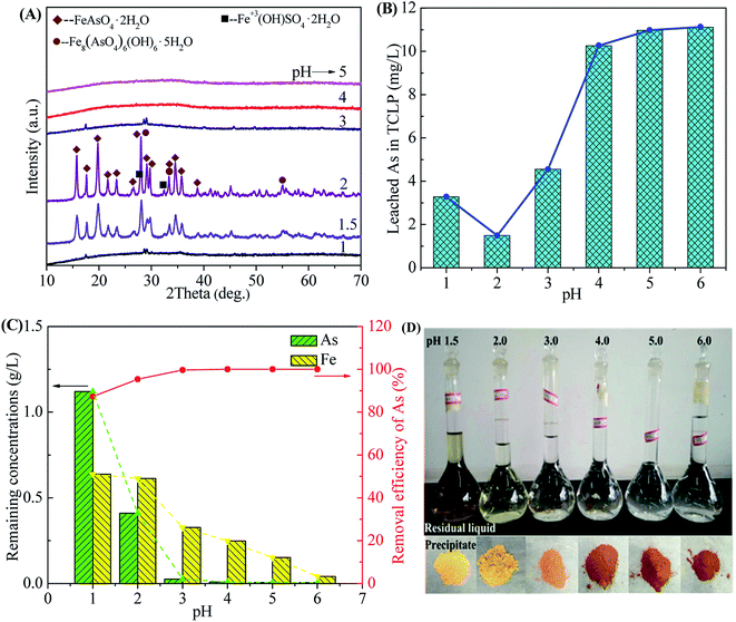 |
| | Fig. 4 The XRD patterns of precipitates (A), leached As of precipitates in the TCLP (B), remaining As concentration and removal efficiency of As in residual liquid (C) and photos of filtrates and precipitates (D) obtained after scorodite synthesis using FeSO4·7H2O (Fe/As = 1.5) at 90 °C as a function of pH ranged from 1 to 6 for 12 hours. | |
The surface structure of precipitates characterized using FTIR technology is shown in Fig. 5. The bands at 1700 cm−1 and 3600 cm−1 are originated from the stretching modes and bending vibrations of combined water. The weak band at around 3180 cm−1 should be ascribed to the O–H stretching mode in tooeleite and butlerite. The surface sulfate is also revealed by the bands at 1047 cm−1 and 1095 cm−1. The band at 513 cm−1 corresponds to Fe–O–As. The FTIR bands in the range of 1400–550 cm−1 observed here are similar to pure scorodite5 and basic ferric arsenate sulfate.59 On the basis of XRD diffractions, the Fe–O–As peaks appear in samples prepared at pH values of 4 or 5 should be ascribed to the amorphous ferric arsenate. This Fe–O–As evidence of sample obtained at a pH of 2.0 is consistent with the scorodite structure (see the XRD results in Fig. 4A). While the sample obtained at a pH of 1.0 and 3.0 might be composed of both scorodite and amorphous ferric arsenate.
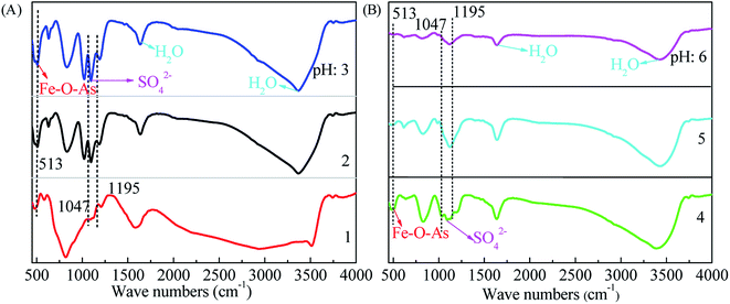 |
| | Fig. 5 The FTIR patterns of precipitates obtained from scorodite synthesis using FeSO4·7H2O (Fe/As = 1.5) at 90 °C as a function of pH values ranged from 1 to 6 ((A), pH 1–3 and (B), pH 4–6) hours for 12 hours. | |
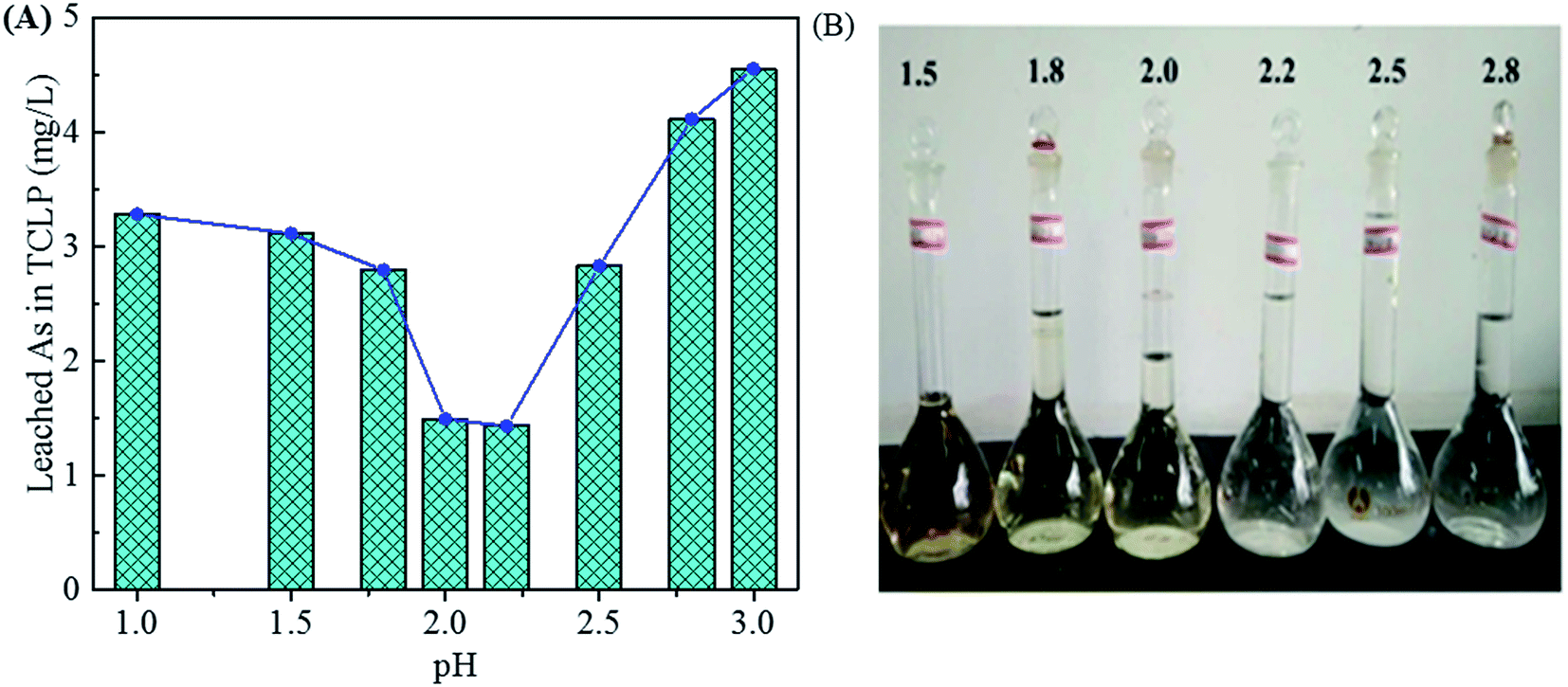
In Fig. 4B, the As leaching concentrations lower than 5 mg L−1 are obtained for the samples precipitated in the pH range of 1.0–3.0 (3.28, 1.49 and 4.55 mg L−1 for pH of 1.0, 2.0 and 3.0, respectively) due to the arsenic immobilization of crystalline scorodite. The As leaching concentrations increase to a high level (around 11 mg L−1) for the precipitates composed of amorphous phases obtained at pHs value ranged from 4.0 to 6.0. The amorphous ferric arsenate and arsenate hydrates leach significantly more than scorodite,60 resulting in an increase of As leaching concentration for samples obtained at higher pH values. Moreover, the pH influence on the As leaching concentration in the range of 1.0–3.0 was studied in details in Fig. 6. The similar trend of pH influence on the As leaching toxicity was obtained. A pH of 2.0 was found to be the best one to prepare scorodite with the lowest As leaching concentration.
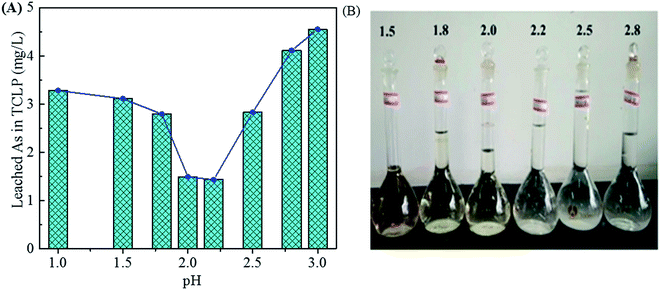 |
| | Fig. 6 The leached As concentration of precipitates in the TCLP (A) obtained from scorodite synthesis using FeSO4·7H2O (Fe/As = 1.5) at 90 °C and pH values of 1.0, 1.5, 1.8, 2.0, 2.2, 2.5, 2.8 and 3.0 for 12 hours. The photos of residual liquids (B). | |
In Fig. 4C, the removal efficiency of As increases from 87.3% to 99.7% when pH increases from 1.0 to 3.0, resulting in a decrease from 1.1 g L−1 to 25 mg L−1 for the remaining As concentration. In the pH range of 4.0–6.0, the removal efficiency of As are close to 100% and the remaining As concentrations are lower than 8 mg L−1. The Fe remaining concentration decreases with an increase of pH due to the formation of Fe–As compounds (see in Fig. 4A) and possible basic ferric sulfate and arsenate at high pH values.35 This precipitation behavior is consistent with the thermodynamics of Fe–As–H2O system.18 The evolution of Fe3+ removal in the solution is also confirmed by a change of colors for solutions in volumetric flasks shown in Fig. 4D.
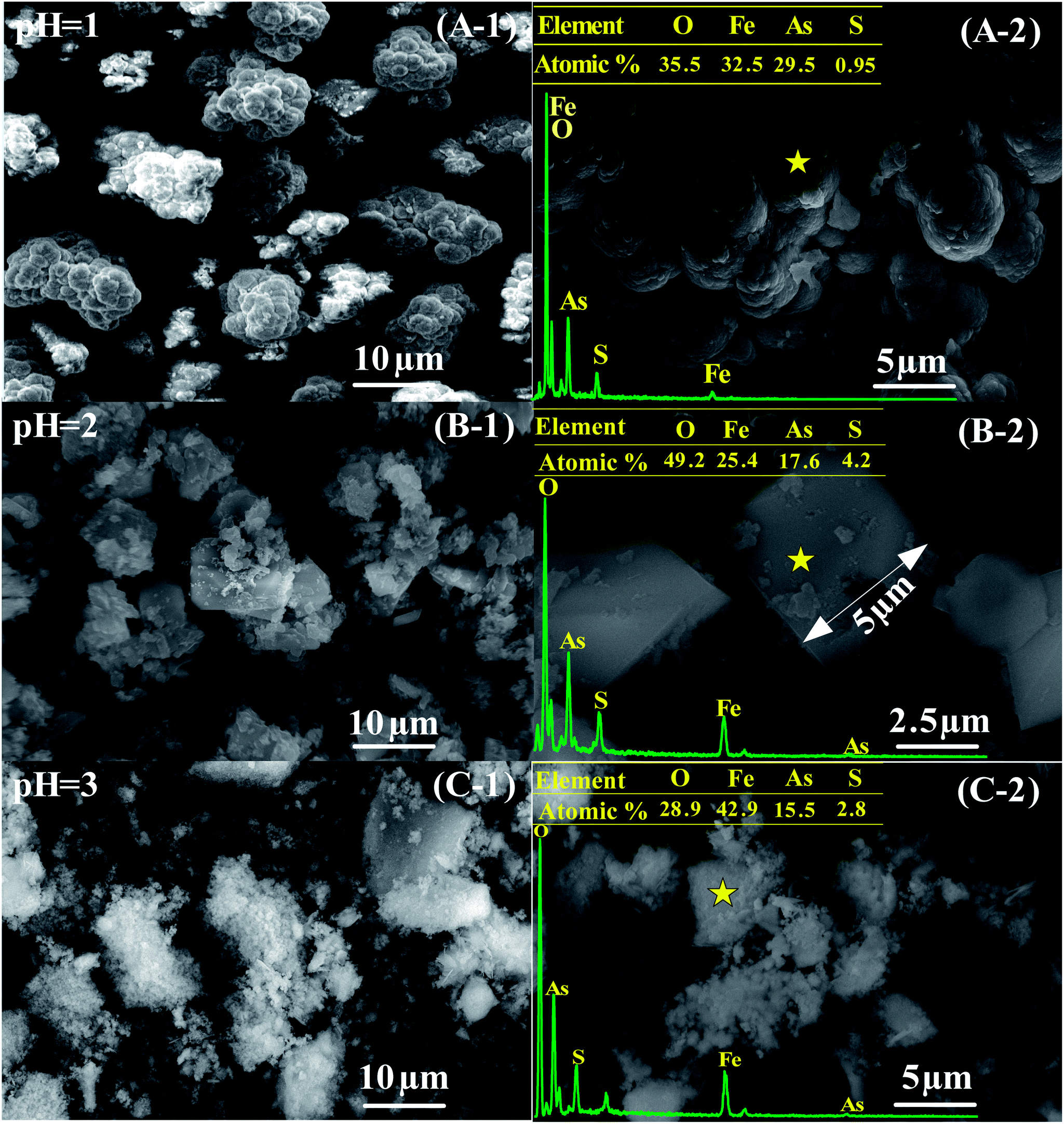
The overview micrographs and elemental compositions of precipitates obtained at pH values of 1.0, 2.0 and 3.0 are shown in Fig. 7. The spheroid particles composed of micro grains are shown in the sample obtained at the pH of 1.0 (see Fig. 7A-1 and A-2). In spite of the poor crystallization (see in Fig. 4A), the precipitate has a chemical composition close to that of FeAsO4·2H2O (an As content of 29.5% vs. an As content of 32.5% in FeAsO4·2H2O). In combination with the XRD result in Fig. 4A, the co-existence of scorodite and amorphous ferric arsenate was confirmed in the sample. A small amount of S was also detected, which should be derived from the co-precipitation of sulfate (Fig. 4A and 5). The micron scorodite grains (grain sizes in the range of 1–5 μm) in forms of biconical and rectangle shapes were obtained at a precipitation pH of 2.0, as shown in Fig. 7B-1 and B-2. Some small grains with a grain size lower than 1 μm were also observed on the surface of big micro grains. This morphology is slight different from those of scorodite prepared by using pure As and Fe sources.47,49 It might be associated with the complex composition of waste acid used in this experiment (Table 1). The As content for the spot (Fig. 7B-2) decreases to 17.6% and S content increases to 4.2%. This may be due to the formation of basic ferric arsenate sulfate. In Fig. 7C-1 and C-2, the sample obtained at the pH of 3.0 presents a flocculent appearance with an As content of 15.5% due to the formation of both amorphous ferric arsenate and scorodite. The high Fe content in this sample should be ascribed to the generation of ferric hydroxide or Fe3+/OH− associated compounds at high pH.33 The scorodite growth is a diffusion-controlled process, building at the expense of the dissolution of small amorphous ferric arsenate particles.58 It is difficult to form large particle at the pH of 3.0 due to the slow resolution of small amorphous ferric arsenate particles.61 The formation of excessive hydroxides and sulfates will also depress the growth of particles by coating the surface at higher pHs value. On the contrary, the resolution of amorphous ferric arsenate is too fast to form a large particle.
 |
| | Fig. 7 The overview micrographs and elemental compositions of precipitates obtained from scorodite synthesis using FeSO4·7H2O (Fe/As = 1.5) at 90 °C in the pH range of 1.0–3.0 for 12 hours. | |
Those results show that environmentally friendly and well-crystallized scorodite with a small amount of impurities (tooeleite, butlerite and rozenite) was obtained at the pH of 2.0, following with a favorable As removal efficiency of 95.3%. A pH of 3.0 is available to achieve a highest As removal efficiency of 99.7% through the formation of nontoxic precipitates in forms of amorphous ferric arsenate and poorly crystalline scorodite. A pH of 2.0 is fixed in the following study to optimize the Fe/As moral ratio, reaction temperature and reaction time in the stage of scorodite synthesis.
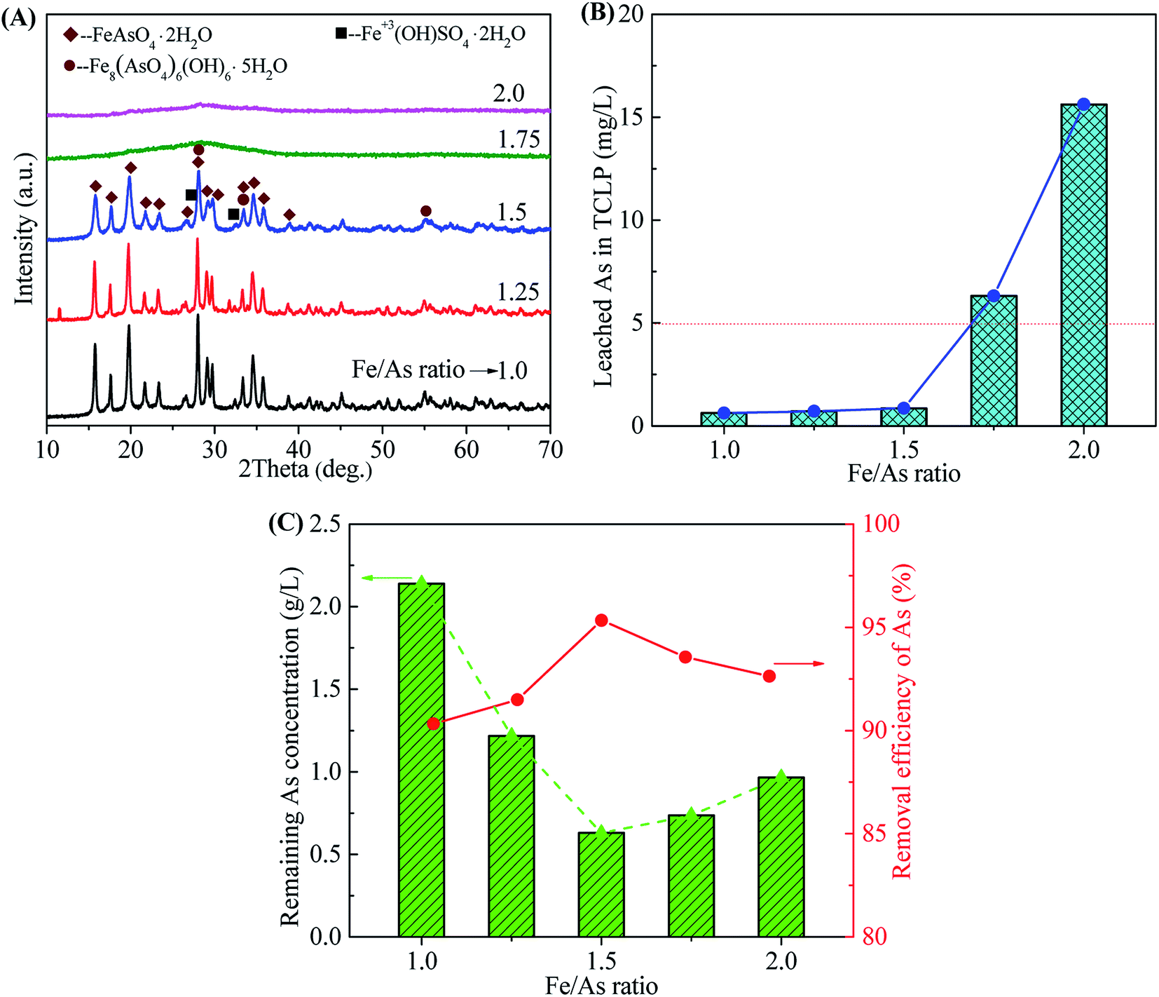
3.2.2 Effect of Fe/As ratio. The crystallization of scorodite is sensitive to the Fe/As molar ratio. A Fe/As ratio in the range of 1.0–3.0 is available for the synthesis of scorodite in different conditions by using pure chemical reagents.32,35,38,46,47,49,62 The influence of Fe/As ratio on the scorodite synthesis was investigated in the range of 1.0–2.0, as shown in Fig. 8. The precipitates obtained at the Fe/As ratios of 1.0, 1.25 and 1.5 show the well-crystallized scorodite structure following with some impurities (tooeleite, butlerite, and rozenite) (Fig. 8A). The wider and weaker diffraction peaks at higher Fe/As ratios reveal a poorer crystallinity. No obvious characteristic peaks were observed in samples obtained at the Fe/As ratios of 1.75 and 2.0 due to the formation of amorphous ferric sulfate, basic ferric arsenate, ferric arsenate and ferric oxyhydroxide.33 The transformation of amorphous ferric arsenate to scorodite was also depressed by amorphous ferric oxyhydroxide at high Fe/As ratios. The well-crystallized scorodite obtained at the Fe/As ratios of 1.0, 1.25 and 1.5 led to the low As leaching concentrations in TCLP (0.62, 0.71 and 0.85 mg L−1 for Fe/As 1.0, 1.25 and 1.5, respectively), as shown in Fig. 8B. The slight decrease of leaching concentrations should be ascribed to the increase of grain size evidenced by XRD results. The samples prepared at high Fe/As ratios with amorphous phases exhibit high As leaching concentrations higher than the regulatory limit of 5 mg L−1 (6.31 and 15.62 mg L−1 at Fe/As ratios of 1.75 and 2.0, respectively). The Fe/As ratios of 1.0, 1.25 and 1.5 are available for the synthesis of crystalline and environmentally stable scorodite. The sample obtained at the Fe/As ratio of 1.5 shows the highest As removal efficiency (95.34%) and the corresponding leaching toxicity (0.71 mg L−1). Fe/As = 1.5 was chosen because excess iron produced a more stable iron arsenate precipitate. At the same time, the experimental results also show that the removal rate of arsenic in the solution under Fe/As = 1.5 is much higher than that at Fe/As = 1. Therefore, we choose Fe/As = 1.5 as the best condition for removing arsenic. At the same time, in order to control the environmental impact of various heavy metal ions in Stage-II filtrate after arsenic removal, the results are shown in Table 3. It can be seen that arsenic removal of arsenic is a comprehensive process. It can effectively remove most of the heavy metal cations while treating arsenic ions.
 |
| | Fig. 8 The XRD patterns of precipitates (A), leached As in TCLP of precipitates (B), remaining As concentrations in residual liquid and removal efficiency of arsenic (C) obtained from scorodite synthesis using FeSO4·7H2O at a pH of 2.0 at 90 °C as a function of Fe/As ratio range from 1.0 to 2.0 after 12 hours reaction time. | |
Table 3 Concentration of heavy metal ions in Stage-II filtrate before and after reaction
| Constituent |
As |
Cu |
Zn |
Sb |
Pb |
Cd |
| Before reaction (g L−1) |
24.50 |
0.16 |
3.81 |
0.17 |
6.99 × 10⁻³ |
0.98 |
| After reaction (g L−1) |
0.14 |
0.11 |
2.9 |
0.12 |
— |
0.69 |
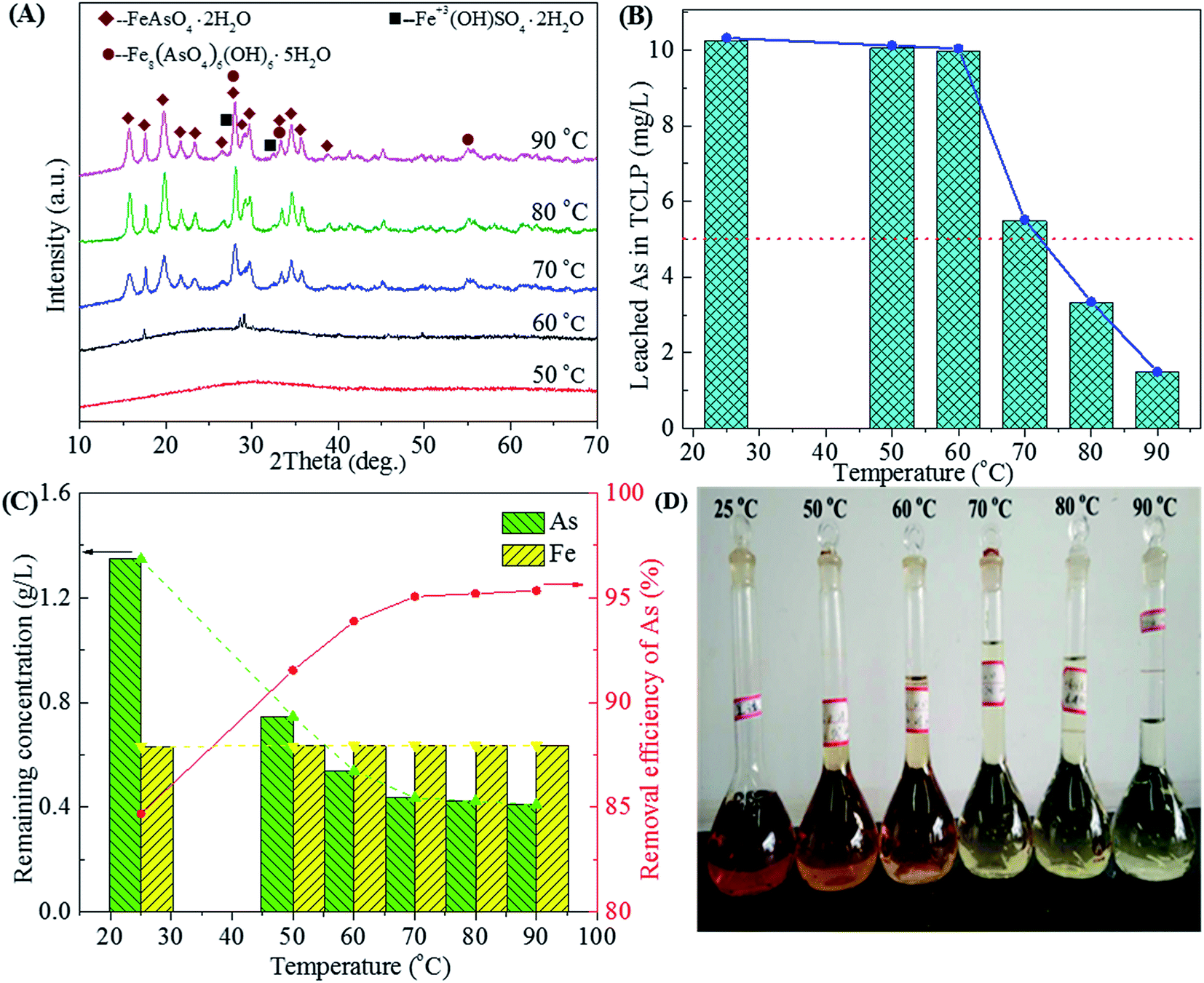
3.2.3 Effect of temperature. The high temperature is favorable for the transformation of amorphous ferric arsenate into scorodite.1,45 The mineralogy of the precipitate and arsenic removal efficiency also depends on the reaction temperature. George P. Demopoulos have reported that crystalline and environmentally stable scorodite could be prepared at temperatures as low as 85 °C by using FeSO4·7H2O as an iron donator.30 The role of the temperature on this precipitation stage was investigated in the range of 25 to 90 °C, as shown in Fig. 9.
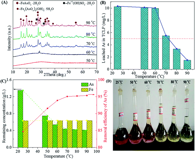 |
| | Fig. 9 The XRD patterns of precipitates (A), leached As in TCLP of precipitates (B), residual As concentration in residual liquid and removal efficiency of arsenic (C) and photos of residual liquid (D) obtained from scorodite synthesis using FeSO4·7H2O (Fe/As = 1.5) at the pH of 2.0 as a function of temperature ranged from 25 to 90 °C. | |
The amorphous ferric arsenate produced at low temperatures (25–50 °C) or at the beginning of the reaction will dissolve and recrystallize at the high temperature to form scorodite.58 The characteristic peaks of scorodite63 begins at 60 °C and are strengthened at the higher temperatures (70, 80 and 90 °C), as shown in Fig. 9A. The well-crystallized scorodite could be synthesized at the temperature as low as 70 °C by using waste acid. The crystallization and growth of grain were intensified with the increase of temperature.58 The As leachability of amorphous ferric arsenate far outweighs that of crystalline scorodite. The amorphous ferric arsenate precipitates obtained in the temperature range of 25–60 °C characterize high As leaching concentrations (10–11 mg L−1), as shown in Fig. 9B. While the As leaching concentration gradually declines with the enhancement of crystallization of scorodite at higher temperatures (3.32 and 1.49 mg L−1 for 80 and 90 °C, respectively). The As removal efficiency also reaches a high level (>95%) and increases slowly in the temperature range of 70–90 °C. The concentrations of As and Fe also remain relatively stable in the temperature range of 50–90 °C (Fig. 9C). The weight of precipitate increases with the increase of temperature due to the enhanced crystallization and As removal efficiency (Fig. 9C and D). A reaction temperature of 90 °C is most favorable to prepare the well-crystallized and environmentally stable scorodite.
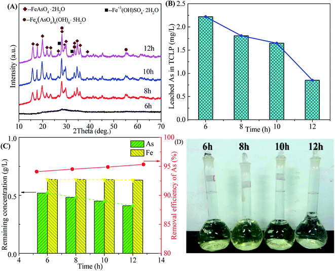
3.2.4 Effect of time. The influence of reaction time on the scorodite synthesis was investigated, as shown in Fig. 10. The well-crystallized scorodite is obtained after 8 hours reaction time and its characteristic peaks are intensified with the increase of reaction time (Fig. 10A). The As leaching concentrations decrease from 2.22 mg L−1 to 0.85 mg L−1 with the proceeding of the reaction, as shown in Fig. 10B. The remaining As concentration in the filtrate-II after solid–liquid separation at the end of precipitation is around 0.5 g L−1 and it declines slowly with the preceding of reaction. The As removal efficiency shows a slowly growing around 95%. The relative transparent filtrates are shown in Fig. 10D, indicating high-efficiency removal of Fe3+ in the solution. The above results indicate that transformation of amorphous ferric arsenate into scorodite proceeds with the increase of reaction time, following with dissolution of amorphous particles, recrystallization of scorodite and growth of scorodite grain. A reaction time equals to or longer than 8 hours is available to produce well-crystallized and environmentally-friendly scorodite.
 |
| | Fig. 10 The XRD patterns of precipitates (A), leached As in TCLP of precipitates (B), residual As concentration in residual liquid and removal efficiency of arsenic (C) and photos of residual liquid (D) obtained from scorodite synthesis using FeSO4·7H2O (Fe/As = 1.5) at the pH of 2.0 and 90 °C as a function of reaction time. | |
For the Stage-II of scorodite precipitation, the optimization reveals that a starting pH of 2.0, Fe/As ratio of 1.5, reaction temperatures ranged from 80 to 90 °C and a reaction time that equals to or longer than 8 hours are feasible to remove the 95% of arsenic in waste acid by the formation of crystalline and environmentally friendly scorodite.
3.3. Prospect of high-arsenic waste acid treatment
The performance of high-arsenic waste acid treatment consisted of calcium carbonate neutralization and scorodite synthesis stages was evaluated in a continuous process on the basis of optimal parameters mentioned above. The mass balance was also studied. The stage I was carried out at 25 °C and the final pH was fixed at 0.5. Stage II was fixed at a starting pH of 2.0, a Fe/As ratio of 1.5 and a temperature of 90 °C for 12 hours. The result of the experiment is shown in Table 4. In Stage I, the white environmentally stable gypsum with an As leaching toxicity of 4.93 mg L−1 was obtained. Due to the negligible amount of arsenic incorporated into gypsum or adsorbed on the surface of gypsum, the 97.83% (corresponding to As loss of 2.17%) of arsenic remained in the Filtrate-I. The dry weight of gypsum (actual dry weight 80.68 g vs. theoretical dry weight of 84.92 g) is close to that of theoretical one calculated based on the change of sulfuric acid concentration (76.56 → 15.48 g L−1) for waste acid. In Stage II, the 98.92% of arsenic was removed from the Filtrate-I through the formation of well-crystallized and nontoxic scorodite, resulting in the Filtrate-II with a pH of 1.68 and the arsenic concentration of 0.24 g L−1. The dry weight of the precipitated scorodite approaches to the theoretical one (actual dry weight of 56.37 g vs. theoretical dry weight of 58.37 g). Furthermore, a conventional lime/ferric salt process is applied to dispose the filtrate-II to produce clean water meeting the Emission standard of pollutants for copper, nickel, cobalt industry (GB 25467-2010)64 in Stage III. The sludge with an As leaching concentration of 2.93 mg L−1 was obtained. In this continuous process, no hazardous solid waste was generated.
Table 4 The result of a continuous process in recent waste acid treatment. The 1000 mL high-arsenic waste acid with an As content of 22.40 g L−1 and a sulfuric acid concentration of 76.56 g L−1 was used as raw material
| Stage |
Substances |
Liquids |
Solids |
LossAs/RemAs |
| V/mL |
CAs/g L−1 |
WTheor/g |
DW/g |
TCLP/mg L−1 |
| Lime/ferric sulfate method. V: volume of solution; CAs: concentration of arsenic; WTheor: theoretical weight; DW: dry weight; LossAs: arsenic loss rate; RemAs: arsenic removal efficiency. |
| Stage I |
Gypsum |
— |
— |
84.92 |
80.68 |
4.93 |
1.07 |
| Filtrate-I |
1000 |
22.16 |
— |
— |
— |
| Stage II |
Scorodite |
— |
— |
56.37 |
58.37 |
4.36 |
97.83 |
| Filtrate-II |
2000 |
0.24 |
— |
— |
— |
| Stage IIIa |
Sludge |
— |
— |
— |
51.20 |
2.93 |
99.85 |
| Clean water |
1850 |
0.36 mg L−1 |
— |
— |
— |
On the basis of the above results, the performance of proposed high-arsenic waste acid treatment process was compared with conventional lime/ferric sulfate and sodium sulfide processes. The result in Table 5 shows that the process is characterized by a zero-emission of hazardous waste. The high-quality gypsum produced in Stage-I. The total quantity of solid wastes is a little higher than that of sodium sulfide method. Besides, this atmospheric treatment process uses the chemical agents and procedures similar to that of conventional lime/ferric sulfate, which will greatly promote the feasibility and accessibility. Thus, it is a low-cost, effective and feasible method for the disposal of waste acid without secondary pollution. The total cost including operating and disposal of solid waste from the processes was evaluated (Table 5). Here, we take the treatment of waste acid emit from a copper smelting plant in southwest China. The cost was calculated according to the fact that the concentrations of As and H2SO4 in inflow waste acid were 76.56 g L−1 and 24.5 g L−1 respectively. The calculated cost for our process was nearly 4380 CNY per day. Compared with the traditional lime–iron salt method, the new method would theoretically save 2872 CNY per day. Meanwhile, the volume of neutralization sludge would decrease.
Table 5 The comparison of our treatment process with lime/ferric salt method and sodium sulfide method. Disposal capacity of waste acid is 400 m3 d−1. The concentrations of As and H2SO4 in waste acid were 76.56 g L−1 and 24.5 g L−1 respectively. The clean water after disposal meets the requirements in GB 25467-2010
| Name |
Gypsum/t d−1 |
Scorodite/t d−1 |
Arsenic sulfide/t d−1 |
Neutralization sludge/t d−1 |
Operating cost/CNY per d |
Disposal expenses of waste solid/CNY per d |
| The data is obtained from the practice of copper smetling plants in southwest China. |
| Our treatment |
50.7R |
38.9 |
— |
26.5 |
1200 |
3180 |
| Lime/ferric salta |
— |
— |
— |
57.1HW |
400 |
6852 |
| Sodium sulfidea |
55.55R |
— |
16.67HW |
19.44 |
4500 |
27780 |
Treatment of high-arsenic waste acid by the stepwise formation of gypsum and scorodite was proved to be feasible and accessible for the high-arsenic waste acid disposal. A further development is also needed on the way to an industrial application. Some detailed technical issues will be studied in future work including: (i) the whole process might be further optimized to reduce the output of solid wastes and the processing cost. The water recycles should be also taken into account to reduce additional wastewater. (ii) The acid-consuming iron sources including iron oxides (Fe2O3 and Fe3O4), goethite (Fe(OH)3) and siderite (FeCO3) might be submitted to replace both calcium carbonate and ferric sulfate, acting the functions of neutralization and scorodite synthesis.
4. Conclusion
The present treatment process for arsenic removal from high-arsenic waste acid mainly are composes of calcium carbonate neutralization (Stage I) and scorodite precipitation (Stage II). In the Stage-I for calcium carbonate neutralization, temperatures ranged from 25 to 65 °C is available for the precipitation of sulfate radical in the form of gypsum. The higher temperatures could further reduce the As leaching concentration but also lead to the formation of impurities in gypsum precipitates. Taken into account balances of minimal arsenic loss and maximal removal rate of sulfuric acid, a final pH of 0.5 is fixed in Stage-I. The nontoxic gypsum with an As leaching concentration of 3.36 mg L−1 below the regulatory limit was obtained, resulting in a sulfuric acid removal rate of 80% with a negligible arsenic loss. In the Stage-II for scorodite synthesis, the crystallization of scorodite is extremely sensitive to pH, Fe/As ratio and temperature when FeSO4·9H2O solution is used as the Fe source. The optimal condition was achieved by applying the synthesis at the starting pH of 2.0, Fe/As ratio of 1.5 and temperature of 90 °C for 12 hours, which achieves an arsenic removal efficiency of 95.34% by the formation of well-crystallized and environmentally stable scorodite. The nontoxic scorodite-associated precipitates could be produced in the pHs ranged from 1 to 3, the Fe/As ratio range of 1.0–1.5 and the temperature greater than or equal to 70 °C, following with the arsenic removal efficiency in the range of 87.30–99.70%. The transformation of amorphous ferric arsenate into crystalline scorodite is enhanced by increasing the temperature or extension the reaction time. The proposed process shows great advantages in the aspects of emission of relative stable general solid waste, effective arsenic removal and good accessibility of chemical reagents and facilities, which will be a promising solution for the low-cost disposal of waste acid for the nonferrous metallurgical industry.
Conflicts of interest
There are no conflicts to declare.
Acknowledgements
This work has been supported by foundation of Yunnan Copper Group, the National Natural Science Foundation of China (project no. 51764036), the Scientific and Technological Leading Talent Projects in Yunnan Province (No. 2015HA019) and the Analysis and Testing Foundation of Kunming University of Science and Technology.
References
- A. M. Nazari, R. Radzinski and A. Ghahreman, Hydrometallurgy, 2017, 174, 258–281 CrossRef CAS.
- S. Bhowmick, S. Pramanik, P. Singh, P. Mondal, D. Chatterjee and J. Nriagu, Sci. Total Environ., 2017, 612, 148–169 CrossRef PubMed.
- Y. Du, Q. Lu, H. Chen, Y. Du and D. Du, J. Water Process Eng., 2016, 12, 41–46 CrossRef.
- J. Cui, Y. Du, H. Xiao, Q. Yi and D. Du, Hydrometallurgy, 2014, 146, 169–174 CrossRef CAS.
- L. Chai, M. Yue, J. Yang, Q. Wang, Q. Li and H. Liu, J. Hazard. Mater., 2016, 320, 620–627 CrossRef CAS PubMed.
- M. Filippi, P. Drahota, V. Machovič, V. Böhmová and M. Mihaljevič, Sci. Total Environ., 2015, 536, 713–728 CrossRef CAS PubMed.
- B. Dousova, F. Buzek, M. Lhotka, S. Krejcova and R. Boubinova, J. Hazard. Mater., 2016, 307, 231–239 CrossRef CAS PubMed.
- R. J. De Klerk, Y. Jia, R. Daenzer, M. A. Gomez and G. P. Demopoulos, Hydrometallurgy, 2012, 111–112, 65–72 CrossRef CAS.
- Y. C. Li, X. B. Min, L. Y. Chai, M. Q. Shi, C. J. Tang, Q. W. Wang, Y. j. Liang, J. Lei and W. J. Liyang, J. Environ. Manage., 2016, 181, 756–761 CrossRef CAS PubMed.
- P. M. Randall, Sci. Total Environ., 2012, 420, 300–312 CrossRef CAS PubMed.
- R. G. Robins, Metall. Trans. B, 1981, 12, 103–109 CrossRef.
- Y. N. Zhu, X. H. Zhang, Q. L. Xie, D. Q. Wang and G. W. Cheng, Water, Air, Soil Pollut., 2006, 169, 221–238 CrossRef CAS.
- M. C. Bluteau, L. Becze and G. P. Demopoulos, Hydrometallurgy, 2009, 97, 221–227 CrossRef CAS.
- M. E. Taboada, P. C. Hernández, E. K. Flores, H. R. Galleguillos and T. A. Graber, J. Chem. Eng. Data, 2009, 54, 3059–3068 CrossRef CAS.
- J. Lei, B. Peng, Y. J. Liang, X. B. Min, L. Y. Chai, Y. Ke and Y. You, Hydrometallurgy, 2018, 177, 123–131 CrossRef CAS.
- J. F. Le Berre, R. Gauvin and G. P. Demopoulos, Metall. Mater. Trans. B, 2007, 38, 751–762 CrossRef.
- M. L. Caetano, V. S. T. Ciminelli, S. D. F. Rocha, M. C. Spitale and C. L. Caldeira, Hydrometallurgy, 2009, 95, 44–52 CrossRef CAS.
- M. A. Gomez, L. Becze, J. N. Cutler and G. P. Demopoulos, Hydrometallurgy, 2011, 107, 74–90 CrossRef CAS.
- P. González-Contreras, J. Weijma and C. J. N. Buisman, Water Res., 2012, 46, 5883–5892 CrossRef PubMed.
- C. Doerfelt, T. Feldmann, R. Daenzer and G. P. Demopoulos, Chemosphere, 2015, 138, 239–246 CrossRef CAS PubMed.
- Z. Yuan, D. Zhang, S. Wang, L. Xu, K. Wang, Y. Song, F. Xiao and Y. Jia, Hydrometallurgy, 2016, 164, 228–237 CrossRef CAS.
- D. Filippou and G. P. Demopoulos, JOM, 1997, 49, 52–55 CrossRef CAS.
- E. Krause and V. A. Ettel, Hydrometallurgy, 1989, 22, 311–337 CrossRef CAS.
- P. Ke and Z. Liu, Can. Metall. Q., 2018, 57, 304–311 CrossRef CAS.
- P. Ke, K. Song and Z. Liu, Hydrometallurgy, 2018, 180, 78–87 CrossRef CAS.
- K. Leetmaa, F. Guo, L. Becze, M. A. Gomez and G. P. Demopoulos, J. Chem. Technol. Biotechnol., 2016, 91, 408–415 CrossRef CAS.
- F. G. Jahromi and A. Ghahreman, J. Hazard. Mater., 2018, 360, 631–638 CrossRef CAS PubMed.
- Y. Sun, Q. Yao, X. Zhang, H. Yang, N. Li, Z. Zhang and Z. Hao, RSC Adv., 2018, 8, 19560–19569 RSC.
- R. C. M. Mambote, M. A. Reuter, A. van Sandwijk and P. Krijgsman, Miner. Eng., 2001, 14, 391–403 CrossRef CAS.
- S. Singhania, Q. Wang, D. Filippou and G. P. Demopoulos, Metall. Mater. Trans. B, 2005, 36, 327–333 CrossRef.
- M. C. Harvey, M. E. Schreiber, J. D. Rimstidt and M. M. Griffith, Environ. Sci. Technol., 2006, 40, 6709–6714 CrossRef CAS PubMed.
- S. Singhania, Q. Wang, D. Filippou and G. P. Demopoulos, Metall. Mater. Trans. B, 2006, 37, 189–197 CrossRef.
- D. Langmuir, J. Mahoney and J. Rowson, Geochim. Cosmochim. Acta, 2006, 70, 2942–2956 CrossRef CAS.
- N. Chen, D. T. Jiang, J. Cutler, T. Kotzer, Y. F. Jia, G. P. Demopoulos and J. W. Rowson, Geochim. Cosmochim. Acta, 2009, 73, 3260–3276 CrossRef CAS.
- T. Fujita, R. Taguchi, M. Abumiya, M. Matsumoto, E. Shibata and T. Nakamura, Hydrometallurgy, 2009, 96, 189–198 CrossRef CAS.
- F. Lagno, S. D. F. Rocha, S. Chryssoulis and G. P. Demopoulos, J. Hazard. Mater., 2010, 181, 526–534 CrossRef CAS PubMed.
- D. Paktunc and K. Bruggeman, Appl. Geochem., 2010, 25, 674–683 CrossRef CAS.
- X. B. Min, Y. P. Liao, L. Y. Chai, Z. H. Yang, S. Xiong, L. Liu and Q. H. Li, Trans. Nonferrous Met. Soc. China, 2015, 25, 1298–1306 CrossRef CAS.
- D. Kossoff, M. D. Welch and K. A. Hudson-Edwards, Chem. Geol., 2015, 406, 1–9 CrossRef CAS.
- J. Majzlan, E. Dachs, A. Benisek and P. Drahota, Hydrometallurgy, 2016, 164, 136–140 CrossRef CAS.
- Y. Kitamura, H. Okawa, T. Kato and K. Sugawara, Ultrason. Sonochem., 2017, 35(Part B), 598–604 CrossRef CAS PubMed.
- N. Okibe, S. Morishita, M. Tanaka, K. Sasaki, T. Hirajima, K. Hatano and A. Ohata, Hydrometallurgy, 2017, 168, 121–126 CrossRef CAS.
- J. E. Dutrizac and J. L. Jambor, Hydrometallurgy, 1988, 19, 377–384 CrossRef CAS.
- G. P. Demopoulos, D. J. Droppert and G. Van Weert, Hydrometallurgy, 1995, 38, 245–261 CrossRef CAS.
- T. Fujita, R. Taguchi, M. Abumiya, M. Matsumoto, E. Shibata and T. Nakamura, Hydrometallurgy, 2008, 90, 85–91 CrossRef CAS.
- T. Fujita, R. Taguchi, M. Abumiya, M. Matsumoto, E. Shibata and T. Nakamura, Hydrometallurgy, 2008, 93, 30–38 CrossRef CAS.
- T. Fujita, R. Taguchi, M. Abumiya, M. Matsumoto, E. Shibata and T. Nakamura, Hydrometallurgy, 2008, 90, 92–102 CrossRef CAS.
- T. Yang, B. Hu, W. Liu, D. Zhang and L. Chen, JOM, 2018, 70, 2022–2026 CrossRef CAS.
- Y. Kitamura, H. Okawa, T. Kato and K. Sugawara, Adv. Powder Technol., 2016, 27, 891–897 CrossRef CAS.
- N. Okibe, M. Koga, S. Morishita, M. Tanaka, S. Heguri, S. Asano, K. Sasaki and T. Hirajima, Hydrometallurgy, 2014, 143, 34–41 CrossRef CAS.
- F. Fu and Q. Wang, J. Environ. Manage., 2011, 92, 407–418 CrossRef CAS PubMed.
- F. Noli, G. Buema, P. Misaelides and M. Harja, J. Radioanal. Nucl. Chem., 2015, 303, 2303–2311 CAS.
- T. S. Anirudhan and M. R. Unnithan, Chemosphere, 2007, 66, 60–66 CrossRef CAS.
- D. Zhang, Z. Yuan, S. Wang, Y. Jia and G. P. Demopoulos, J. Hazard. Mater., 2015, 300, 272–280 CrossRef CAS PubMed.
- G. Morin, F. Juillot, C. Casiot, O. Bruneel, J. Personné, F. Elbazpoulichet, M. Leblanc, P. Ildefonse and G. Calas, Environ. Sci. Technol., 2003, 37, 1705–1712 CrossRef CAS.
- P. Lu and C. Zhu, Environ. Earth Sci., 2011, 62, 1673–1683 CrossRef CAS.
- T. Nishimura and R. G. Robins, Miner. Eng., 2008, 21, 246–251 CrossRef CAS.
- D. Paktunc, J. Dutrizac and V. Gertsman, Geochim. Cosmochim. Acta, 2008, 72, 2649–2672 CrossRef CAS.
- M. A. Gomez, H. Assaaoudi, L. Becze, J. N. Cutler and G. P. Demopoulos, J. Raman Spectrosc., 2010, 41, 212–221 CAS.
- T. Fujita, S. Fujieda, K. Shinoda and S. Suzuki, Hydrometallurgy, 2012, 111–112, 87–102 CrossRef CAS.
- D. Paktunc, J. Dutrizac and V. Gertsman, Geochim. Cosmochim. Acta, 2008, 72, 2649–2672 CrossRef CAS.
- Y. Kitamura, H. Okawa, T. Kato and K. Sugawara, Ultrason. Sonochem., 2017, 35B, 598–604 CrossRef PubMed.
- J. McLeod, A. H. J. Paterson, J. R. Jones and J. E. Bronlund, Int. Dairy J., 2011, 21, 455–461 CrossRef CAS.
- K. Zheng, Z. Q. Liu, Y. Huang, F. Chen, C. H. Zeng, S. Zhong and S. W. Ng, Sens. Actuators, B, 2018, 257, 705–713 CrossRef CAS.
|
| This journal is © The Royal Society of Chemistry 2020 |
Click here to see how this site uses Cookies. View our privacy policy here. 
 Open Access Article
 This Open Access Article is licensed under a Creative Commons Attribution-Non Commercial 3.0 Unported Licence
 ,
Yongkui Li,
Longhua Wei,
Fengyan Hao,
Xing Zhu*,
Yonggang Wei,
Kongzhai Li and
Hua Wang
,
Yongkui Li,
Longhua Wei,
Fengyan Hao,
Xing Zhu*,
Yonggang Wei,
Kongzhai Li and
Hua Wang