 Open Access Article
Poly(p-phenylene)s tethered with oligo(ethylene oxide): synthesis by Yamamoto polymerization and properties as solid polymer electrolytes†
Hannes
Nederstedt
 and
Patric
Jannasch
 *
*
Polymer & Materials Chemistry, Department of Chemistry, Lund University, P.O. Box 124, SE-221 00 Lund, Sweden. E-mail: patric.jannasch@chem.lu.se
First published on 2nd March 2020
Abstract
Salt-containing supramolecular assemblies of rigid-rod polymers tethered with flexible ion-solvating side chains represent a synthetic pathway towards thin ion-conducting solid electrolyte membranes with high dimensional stability. In the present work we have synthesized poly(p-phenylene)s (PpPs) carrying di-, tri- and tetra(ethylene oxide) side chains, respectively. p-Dichlorophenyl oligo(ethylene oxide) monomers were polymerized by Ni-mediated Yamamoto polymerization via in situ reduction of Ni(II). This gave PpPs with an average degree of polymerization reaching 60, where each phenylene ring carried one oligo(ethylene oxide) side chain. Results from calorimetry and X-ray scattering measurements clearly showed the formation of molecular composites, i.e., bicontinuous morphologies with mechanically reinforcing layers of the stiff PpP backbones separated by the flexible oligo(ethylene oxide) side chains. This morphology was retained after adding lithium bis(trifluoromethane)sulfonimide (LiTFSI) to form salt-in-polymer electrolytes, but with an increased distance between adjacent backbones. Furthermore, upon addition of salt the order-to-disorder transition (ODT) region increased from ∼50–170 °C to ∼75–200 °C at [EO]/[Li] = 20. Increasing salt concentrations also revealed a maximum in the ODT enthalpy at [EO]/[Li] = 40. At 80 and 160 °C, the ionic conductivity reached 1.1 × 10⁻⁴ and 1.0 × 10⁻³ S cm−1, respectively. Finally, we demonstrate that ionic conductivity of the polymer electrolytes can be significantly increased by additions of triglyme.
1. Introduction
Solid polymer electrolytes ideally combine high ionic conductivity and mechanical strength, and essentially consist of a polymer host material containing a dissolved salt.1,2 This class of materials has been extensively studied in, e.g., the development of solid-state batteries, solar cells, electrochromic devices and different sensors and actuators.3–9 They are considerably less unstable and flammable than the currently dominating liquid-based electrolytes, and in some cases possess the necessary electrochemical stability and mechanical properties to operate directly with lithium metal electrodes without dendrite formation during battery cycling.10,11 With a suitable molecular design, solid polymer electrolytes may reach sufficiently high conductivity above ambient temperature, and if applied as thin films or membranes the resistance of solid polymer electrolytes can be kept sufficiently low. However, the conduction of the ions in a solid polymer electrolyte is normally coupled to the segmental motions of the polymer, and hence to the glass transition temperature (Tg).12–14 Consequently, the mechanical stability (stiffness) and ionic conductivity are generally conflicting properties, unless crosslinked or microphase separated solid polymer electrolytes are employed.15,16 In the latter case, the polymers are usually molecularly designed to form a co-continuous morphology containing a “soft” ion-conducting phase domain to facilitate the ion conductivity, interconnected to a “hard” phase domain to induce the mechanical stability. The most common examples of such polymers are perhaps di- and triblock copolymers of, e.g., poly(ethylene oxide) (PEO) and polystyrene, designed to self-assemble into co-continuous morphologies consisting of a soft ion conducting PEO phase domain and a hard glassy polystyrene phase domain.17,18Rigid-rod polymers tethered with short flexible ion-conducting side chains represent an alternative synthetic approach to solid polymer electrolytes combining high ion conductivity and mechanical stability. These kind of “hairy-rod”19,20 polymers typically self-organize into supramolecular assemblies where the rigid-rod polymer backbones stack up to form a hard phase domain in a soft phase domain containing the highly flexible side chains.21,22 Hence, the former materials form “molecular composites” where the stiff stacks of the rigid rod backbones mechanically reinforce the soft side chain phase in a co-continuous arrangement. The phase domains in these polymers are thus characteristically much smaller than in the case of block copolymers. The concept of “molecular composite electrolytes” was originally introduced and demonstrated by Wegner and coworkers who first prepared poly(p-phenylene) (PpP) backbones carrying flexible oligo(ethylene oxide) (EOx) side chains by Suzuki coupling reactions, and then added lithium salt to study their properties as solid polymer electrolytes.19 The electrolytes showed fully amorphous EOx phases with Tg values down to −25 °C, and the phase structure of the molecular composite electrolytes remained stable up to at least 90 °C. Moreover, the conductivity behavior of these materials was found to be similar to that of corresponding electrolytes prepared from amorphous PEO, but the mechanical properties were significantly improved.19 However, the use of two homobifunctional monomers in the Suzuki coupling approach to the polymers resulted in severe limitations in the chain growth, and the degrees of polymerization reached only Xn = 11–17.19 Moreover, every second phenylene ring in the PpP backbone did not carry any EOx side chain which may impede the ion conduction pathway.
The Yamamoto coupling reaction, where two aryl halides are coupled together through the use of a nickel(0) reagent, presents an attractive alternative to the Suzuki coupling approach.23,24 The former reaction is an efficient way to polymerize not only aryl dibromides, but also aryl dichlorides,25,26 which increases the versatility and monomer availability. Moreover, a precise stoichiometric control of the monomers in the polymerizations is not necessary since the Yamamoto reaction occurs via homocoupling. Recently, this reaction has been utilized in polymerizations to prepare proton conducting polymers for use as proton exchange membranes,25–29 as well as lithium ion conducting polymers.30 In the present work, we have employed the Yamamoto homocoupling route for straightforward and efficient polymerizations of 2,5-dichlorophenolic monomers functionalized with di-, tri- or tetra(ethylene glycol), respectively. This provides a molecular design in which every phenylene unit in the PpP backbone carries an EOx side chain to create an even distribution along the backbone. Hence, short side chains (x = 2, 3 or 4) were attached to the PpP backbone to give an EOx content below 75 wt% which will, combined with the even distribution, likely facilitate the formation of morphologies with a continuous phase domain of flexible EOx side chains containing a molecularly ordered and mechanically reinforcing layers of stiff PpP backbones. After additions of lithium bis(trifluoromethanesulfonimide) (LiTFSI) salt, the resulting solid molecular composite electrolytes were investigated with regard to the ability to form thin electrolyte membranes, thermal transitions and phase behavior, self-assembly and morphology, and ionic conductivity in order to determine important structure–property relationships.
2. Experimental
2.1. Materials
Di(ethylene glycol) monomethyl ether (Janssen Chimica, 99%), tri(ethylene glycol) monomethyl ether (Fluka, 97%), tetra(ethylene glycol) monomethyl ether (FluoroChem, 95%), sodium hydroxide (NaOH, Merck, 99%), p-toluenesulfonyl chloride (TsCl, Sigma-Aldrich, 98%), potassium carbonate (K2CO3, Fisher Chemical, Reagent), 2,5-dichlorophenol (Alfa Aesar, 98%), N-methyl-2-pyrrolidone (NMP, Sigma-Aldrich, anhydrous 99.5%), chloroform (CHCl3, VWR, HPLC), and acetonitrile (MeCN, Scharlau, Reagent) were all used as received. Tetrahydrofuran (THF, VWR, Reagent) employed in the tosylation reaction was used as received. Lithium bis(trifluoromethane)sulfonimide (LiTFSI, Fluka, 99%) was dried at 150 °C under vacuum. THF used for film casting was dried by a MBraun 800 solvent dispenser SPS system and further dried with freshly activated molecular sieves (4 Å). Tri(ethylene glycol) dimethyl ether (triglyme, Acros Organics, 99%) was dissolved and azeotropically distilled in toluene, followed by the removal of the toluene at 120 °C under nitrogen, and drying under vacuum at 120 °C overnight. LiTFSI, the anhydrous THF, and the triglyme were subsequently stored in an N2 filled glovebox.The chemicals listed just below were purified as specified and then stored in an Ar filled glovebox (H2O < 1 ppm, O2 < 60 ppm). Triphenylphosphine (PPh3, Acros Organics, 99%) and 2,2′-bipyridine (bipy, TCI, 99%) were recrystallized twice in ethanol and dried at 80 °C under vacuum.25 Sodium iodide (NaI, Sigma-Aldrich, 99%) was recrystallized twice in water and dried at 120 °C in vacuum.25 Zink powder (Zn, Sigma-Aldrich, 98%, <10 μm) was stirred in acetic acid, washed extensively with diethyl ether, and dried at 40 °C under vacuum.31 Bis(triphenylphosphine)nickel(II) dichloride (Ni(PPh3)2Cl2, Sigma-Aldrich, 98%) was dried under vacuum at 100 °C.25
2.2. Oligo(ethylene oxide) monomethyl ether tosylate (MeEOxTs)
The tosylation of oligo(ethylene oxide) monomethyl ethers containing 2, 3, and 4 EO units, respectively, was based on a literature method.32 The synthesis of MeEO3Ts is given as an example. First, 11.582 g (1 eq.) tri(ethylene oxide) monomethyl ether was mixed in 50 ml THF, followed by addition of 9.875 g (3.5 eq.) of NaOH dissolved in 50 ml of water. The resulting two-phase system was cooled to 0 °C followed by dropwise addition of 16.137 g (1.2 eq.) of TsCl dissolved in 70 ml THF. The mixture was stirred at 0 °C during 2 h and then stirred at room temperature overnight. Next, the mixture was poured into 5% HCl, and the aqueous phase was extracted with chloroform. The combined organic phases were washed with deionized water and brine. Subsequently, the organic phase was dried with MgSO4, filtered, and concentrated under vacuum. An amount of 21.189 g (94%) of product was obtained. 1H NMR (400 MHz, CDCl3, ppm) δ 7.78 (d, 2H), 7.33 (d, 2H), 4.41 (t, 2H), 3.67 (t, 2H), 3.62–3.56 (m, 6H), 3.54–3.49 (m, 2H).2.3. α-(2,5-Dichlorophenoxy)-ω-methyl-oligo(ethylene oxide) (pPCl2-EOx)
The synthesis of p-dichlorobenzene bearing oligo(ethylene oxide) chains with 2, 3, and 4 EO units, respectively, was based on a modified literature method.33 In the synthesis of pPCl2-EO3, 10.357 g (1 eq.) MeEO3Ts, 5.374 g (1.01 eq.) 2,5-dichlorophenol, 6.835 g (1.52 eq.) K2CO3, and 100 ml MeCN were added to a round bottom flask. The mixture was heated to reflux, and the pink-colored suspension was stirred overnight. After cooling to room temperature, the mixture was filtered, and the filtrate was concentrated under vacuum. Subsequently, the filtrate was dissolved in diethyl ether, washed with deionized water, dried with MgSO4, filtered, and concentrated under vacuum. A total 9.562 g (95%) of the product pPCl2-EO3 was obtained. 1H NMR (400 MHz, CDCl3, ppm) δ 7.21 (d, 1H), 6.90 (d, 1H), 6.83 (dd, 1H), 4.12 (t, 2H), 3.85 (t, 2H), 3.75–3.71 (m, 2H), 3.65–3.59 (m, 4H), 3.52–3.47 (m, 2H), 3.33 (s, 3H).2.4. Poly(p-phenylene) tethered with oligo(ethylene oxide) [P(pP-EOx)]
In the Ar-filled glovebox, 8.887 g (34 eq.) pPCl2-EO3, 0.559 g (1 eq.) NiCl2(PPh3)2, 0.132 g (1 eq.) bipy, 2.884 g (13 eq.) PPh3, 2.747 g (49 eq.) Zn, and 0.550 g (4.3 eq.) NaI were added to a schlenk flask. The flask was removed from the glove box and placed under Ar-atmosphere. A volume of 50 ml of anhydrous NMP was added and the mixture was stirred at 80 °C under Ar during 5 days. The reaction mixture was cooled to room temperature and poured into 500 ml 1.5 wt% HCl. After 1 h of stirring, 100 ml of DCM was added to the suspension, and the resulting mixture was stirred vigorously during 3 h. The aqueous phase was then extracted with 2 × 100 ml of DCM. The combined organic phase was washed with deionized water, dried with MgSO4, filtered, and concentrated under vacuum. The yellow/orange oil was diluted with DCM (85 ml) until slightly viscous and precipitated in diethyl ether (850 ml). The white solid was filtered, washed with diethyl ether. An amount of 5.076 g (74%) of the product P(pP-EO3) was obtained after drying under vacuum at 50 °C. 1H NMR (400 MHz, CDCl3, ppm) δ 7.65–7.17 (m, 3.5H), 4.27 (t, 2H), 4.00–3.46 (m, 10H), 3.37 (s, 3H).2.5. Polymer electrolyte membranes
Prior to casting electrolyte membranes, the polymers in the P(pP-EOx) series were dried during three days under vacuum at 60 °C, followed by two days under high vacuum (0.2 Pa) at 80 °C. The polymers were then stored in the N2-filled glove box. In the same glove box, approximately 0.12 g of polymer and the appropriate amount of LiTFSI were dissolved in 2 ml dry THF. This solution was stirred during 24 h and then removed from the glovebox. The solution was poured into a Teflon Petri dish, which was then immediately placed in a desiccator under a flow of dry nitrogen. After casting during 1 day, the membrane was further dried under vacuum during 1 day. Subsequently, it was removed from the Petri dish and stored in the Ar filled glovebox. The casting procedure was repeated for P(pP-EO3) and P(pP-EO4) with different amounts of LiTFSI salt added. This yielded polymer electrolyte membranes [designated P(pP-EOx)-y] with various salt concentrations (y) expressed the number of EO units per lithium ion.2.6. Characterization
All NMR spectra were collected using a Bruker DR X400 spectrometer 400.13 MHz, employing CDCl3 (δ = 7.26 ppm) solutions of the samples. The molar masses of the polymers were determined using size exclusion chromatography (SEC) at 35 °C on a Viscotec TDAmax system equipped with OmniSEC Triple Detectors (refractive index, viscosity, and light scattering). The SEC system was fitted with a 2 × PL-Gel Mix-B LS column set (2 × 30 cm), and CHCl3 was used as eluent. A CHCl3 solution of a polystyrene standard (Polymer Laboratories, Mp = 96 kg mol−1, ĐM = 1.03) was used for calibration.Thermogravimetric analysis (TGA) was performed using a TA instruments Q500 Thermogravimetric Analyzer. Samples were dried at 120 °C for 30 minutes under nitrogen, followed by cooling to 50 °C, and heating to 600 °C at a heating rate of 10 °C min−1. Differential scanning calorimetry (DSC) was performed on a TA instruments Q2000 calorimeter. Polymer samples were placed in aluminum pans that were subsequently sealed. The measurements started by heating the samples to 200 °C, followed by cooling to −80 °C, an isothermal period of 10 min at this temperature, and finally heating to 200 °C. All heating and cooling rates were 10 °C min−1.
For the ionic conductivity measurements, circular pieces of the electrolyte films with a diameter of 12 mm were cut out in the Ar filled glove box. These were placed between two gold-plated brass coin electrodes (Ø = 15 mm) separated by a Teflon ring spacer with an inner diameter of 12 mm and a thickness of 0.112 mm. Electrochemical impedance spectroscopy (EIS) measurements were performed using a computer controlled Novocontrol BDC40 high resolution dielectric analyzer equipped with a Novocool cryostat unit. The samples were analyzed in the frequency range 10−1–107 Hz at a 50 mV AC amplitude during heating–cooling-heating cycles between 20 and 160 °C. At 20 °C intervals, the DC conductivity was obtained by extrapolation from the plateau value in a log–log plot of the real part of the complex conductivity as a function of the ac frequency (Fig. S6†).
Wide angle X-ray scattering (WAXS) measurements were performed using a Stoe STADI MP X-ray powder diffractometer under ambient conditions. Measurements were performed over 2θ ranges 1–70° with copper Kα (0.15406 nm) radiation. Samples were prepared in the Ar glove box by placing a piece of the polymer films between two Mylar sheets.
3. Results and discussion
3.1. Monomer and polymer synthesis
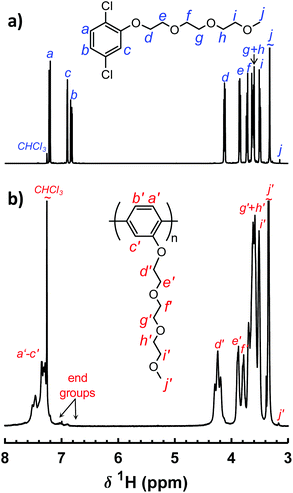
The polymers in the P(pP-EOx) series were molecularly designed to tether every single phenylene unit in the PpP backbones with exactly one short side chain of precisely 2, 3 or 4 EO units, respectively (Scheme 1). This creates an even distribution of short flexible side chains along the backbone to facilitate the formation of morphologies with molecularly ordered and mechanically reinforcing layers of stiff PpP backbones separated by flexible EOx side chains. Upon addition of salt, the dense and evenly distributed side chains may also decrease the distance between each EO–Li coordination site in the solid polymer electrolyte. The P(pP-EOx) samples were prepared via Yamamoto homocoupling reactions of 2,5-dichlorophenol monomers functionalized with the corresponding EOx side chain. The monomer synthesis started with the tosylation of di-, tri-, and tetra(ethylene glycol) monomethyl ether, respectively, in a THF-water two-phase system. After workup, all the excess TsCl had been removed and hence no chromatographic method was necessary. Subsequently, the monomers (designated pPCl2-EOx) were then synthesized by Williamson's ether synthesis from 2,5-dichlorophenol and the corresponding tosylate. The structure of the monomers was confirmed by 1H NMR spectroscopy (Fig. 1a). Signals arising from the aromatic protons (i.e., the hydrogen at a–c) were readily distinguished by their respective shifts and splittings. The signals arising from the protons on the EOx side chains (i.e., d–j) continuously decreased in chemical shift from the protons at the α-methylene, d, (4.12 ppm) to the ω-methyl, j, (3.33 ppm).34Yamamoto coupling is a nickel-mediated reaction in which Ni(0) is used to couple two aryl halides (ArCl, ArBr, or ArI) to form a carbon–carbon bond. A common reagent for this type of coupling is bis(cyclooctadiene)nickel(0), used in (at least) stoichiometrically equal amounts to the monomer.27,28,34 This reagent is air sensitive and fairly expensive, which impedes scale up of the reaction. In the present work, an alternative method was used in which a small amount of a nickel(II) reagent (i.e., bis(triphenlyphosphine)nickel(II) dichloride) was continuously reduced in situ by zinc metal.23,25,26,35 The reaction mixture was still prepared in a glove box to protect against moisture, since nickel(0) is an efficient reagent for the dehalogenation of aryl halides in presence of hydrogen sources such as water. As suggested by Colon and Kelsey,31 2,2′-bipyridine was added to suppress side reactions that often arise when monomers with electron donating groups are used. Using this method, the polymers in the P(pP-EOx) series were successfully prepared in ∼5 g scale, and in ∼70% isolated yield for (PpP-EO2) and (PpP-EO3). After polymerization, the products were precipitated in diethyl ether to remove the PPh3. Most probably, this procedure also removed some of the low molar mass oligomers formed. Especially sample P(pP-EO4) showed partial solubility in diethyl ether due to the long EO4 side chains, which led to some product loss during the purification and a lower isolated yield (20%).
The molecular structure of the polymers was confirmed by 1H NMR spectroscopy (Fig. 1b). As expected, the 1H NMR signals of the polymers were broadened in comparison to the signals of the corresponding monomer. Due to the conjugated structure the signals arising from the protons at a′–c′ formed one broad signal. The signals from the protons at d and j on the EOx side chains were still clearly distinguished. Furthermore, all the polymer spectra included small signals from the end groups of the PpP backbones at ∼7 ppm.34 The integrals of these end group signals were compared with the integral of signal d′ in each polymer in order to estimate the degree of polymerization (Table 1). Notably, no broad signals were observed between δ 5.40–5.80 ppm, which might indicate the absence of Ni complexes bound to the polymer.17 The molar mass of the P(pP-EOx) samples was determined using a SEC setup fitted with a triple detector system. The results showed that all polymers had a number average degree of polymerization very close to Xn = 60, which was similar to the results obtained from the 1H NMR spectra and corresponded to number average molar masses between Mn = 12 and 17 kg mol−1 (Table 1 and Fig. S3†). In comparison, Wittmeyer et al. reached a degree of polymerization close to 21 in polymerizations of dibromobenzene functionalized with two oligo-EO side chains using an excess of Ni(COD)2.34 The molar mass dispersities of the present polymers were between ĐM = 1.4 and 1.6, which was very narrow compared to previously reported poly(p-phenylene)s.19,29,34 The combination of high Xn and low ĐM values indicates a high level of control in the present polymerizations.
| Sample | EOx content (wt%) | Yield (%) | M n (kg mol−1) | Đ M | X n | X n | a |
T
d
95![[thin space (1/6-em)]](https://www.rsc.org/images/entities/char_2009.gif) f (°C) f (°C) |
T g (°C) | ΔHfh (J g−1) | ΔHci (J g−1) |
|---|---|---|---|---|---|---|---|---|---|---|---|
| a Number average molar mass (SEC). b Molar mass dispersity (SEC). c Number average degree of polymerization from SEC. d Number average degree of polymerization from NMR. e Mark–Houwink exponent (SEC). f Temperature at 5 wt% weight loss (TGA, under N2). g Glass transition temperature (DSC, heating 10 °C min−1). h ODT enthalpy (DSC, heating 10 °C min−1). i DOT enthalpy (DSC, cooling 10 °C min−1). j Low isolated yield due to loss during workup. | |||||||||||
| P(pP-EO2) | 61 | 79 | 12 | 1.6 | 61 | 68 | 1.2 | 403 | — | 16 | 14 |
| P(pP-EO3) | 68 | 74 | 14 | 1.6 | 60 | 58 | 1.1 | 398 | −48 | 11 | 11 |
| P(pP-EO4) | 73 | 20j | 17 | 1.4 | 61 | 68 | 1.4 | 393 | −54 | 14 | 10 |
The intrinsic viscosity ([η]) measured during the SEC analysis, enabled the calculation of the parameters in the Mark–Houwink equation ([η] = K × Ma). As seen in Table 1, the exponent a was above 1 for the P(pP-EOx) samples, which indicated that the polymers attained a stiff or rigid rod conformation, rather than a conventional random coil conformation in chloroform. This was due to the very high chain stiffness of the PpP backbone, which instead induced stiff coil or rigid rod conformations.36,37
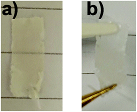
Films of the neat P(pP-EOx) samples were cast from THF solutions. P(pP-EO2) exhibited limited solubility in THF, resulting in very brittle films. However, casting P(pP-EO2) from CHCl3 solutions resulted in flexible and self-standing films (Fig. S4†). In contrast, both P(pP-EO3) and P(pP-EO4) formed very soft films regardless of the solvent used. Subsequently, the possibility to cast polymer electrolyte membranes from mixtures of the polymers and LiTFSI salt dissolved in THF was investigated, keeping [EO]/[Li] between 10 and 40. The resulting materials were denoted P(pP-EOx)-y, where y = [EO]/[Li]. Since no solvent was found that fully dissolved both P(pP-EO2) and LiTFSI, no salt-containing membranes could be prepared from this polymer. Consequently, this polymer was not characterized as an electrolyte material. P(pP-EO3) formed self-standing membranes when [EO]/[Li] was between 40 and 20 (Fig. 2); P(pP-EO3)-10 was very brittle. Of the electrolyte films derived from P(pP-EO4), only P(pP-EO4)-10 was self-standing. Lower salt concentrations ([EO]/[Li] > 40) produced membranes that were too soft for handling.
3.2. Thermal stability
The thermal decomposition of the neat P(pP-EOx) polymers was measured by TGA, and the results are shown in Fig. 3a. Weight loss of the samples was only observed above ∼390 °C and occurred in only one step, most likely through the exclusive loss of the EOx side chains. This most probably started by scission of the bond between the phenolic oxygen and the α-methylene group, followed by decomposition of the EOx residue.19 As expected, longer side chains led to a higher degree of weight loss and lower Td95. The ash content at 600 °C roughly corresponded to the weight fraction of the aromatic backbone (Fig. 3b), which indicated that very little of the PpP backbone had decomposed. In conclusion, all the polymers exhibited high thermal stability, sufficient for application as polymer electrolytes.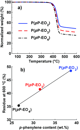 | ||
| Fig. 3 TGA traces of neat P(pP-EOx) samples under N2 (a) and residual weight percent at 600 °C as a function of PpP content (b). | ||
3.3. Phase behavior
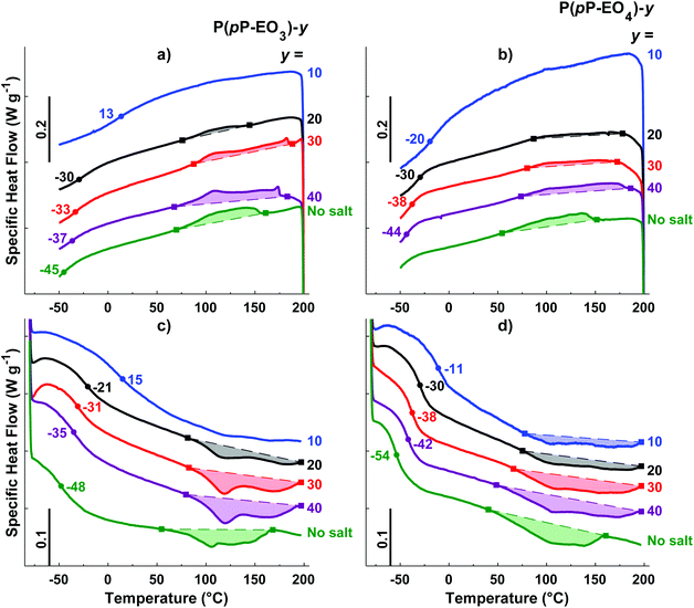
DSC was employed to study the thermal transitions of the neat P(pP-EOx) polymers (Fig. 4) and the corresponding polymer electrolytes (Fig. 5). None of the samples exhibited any endothermic transition between 0 and 40 °C, indicating that the side chains were completely amorphous. Glass transition temperatures (Tgs) originating from the EOx phase of P(pP-EO3) and P(pP-EO4) were observed at −48 and −54 °C, respectively. Hence, the Tg of P(pP-EO4) was slightly lower than that of P(pP-EO3), due to its longer side chains. No Tg of P(pP-EO2) was observed, presumably due to the short side chains and hence low EOx phase content.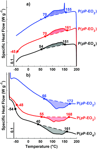 | ||
| Fig. 4 DSC cooling (a) and heating (b) traces of the polymers in the P(pP-EOx) series (exotherm up). Tgs were taken as the inflexion points, marked by ●. The ODT and DOT intervals are marked by ■. | ||
As can be seen in Fig. 4b, all three P(pP-EOx) samples exhibited endotherms between 75 and 175 °C, which was likely connected with an order-to-disorder transition (ODT) which involved the disruption of the PpP stacks.19,38 The broadness of the transitions may arise from the molar mass dispersity leading to an increase in transition temperature with polymer molar mass.19,38 The onset and end of these transitions were shifted to lower temperatures as the length of the EOx side chain increased. This indicated that the phase structures became less thermally stable with an increase in the length and content of the EOx side chains. The values of the enthalpy of the transitions could not be accurately determined due to the rather unclear onset and end of the transitions. Hence, no clear trends could be discerned. The length of the EOx side chains likely had two effects on the enthalpy of the ODT; one increasing effect due to the lowering of the melt viscosity and one decreasing effect due to the less efficient packing of the PpP when the EOx content increased. Upon cooling, a corresponding exothermic disorder-to-order transition (DOT) was observed for all polymers at approximately the same temperature interval as the ODT transitions (Fig. 4a). This was likely connected with the ordering of the PpP backbone, and the DOT enthalpy was approximately the same as the ODT enthalpy for a given sample (Table 1).
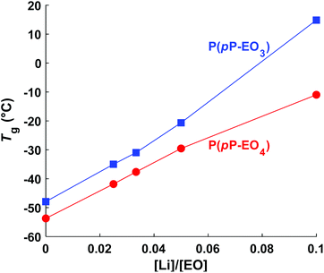
Upon addition of LiTFSI, the Tg increased and continued to increase with increasing salt concentration (Fig. 5a–d and Fig. 6) up to a value of 15 and −11 °C for P(pP-EO3)-10 and P(pP-EO4)-10, respectively. This was due to the increase in the coordination between the EOx units and the lithium ions.38,39 Addition of LiTFSI affected the ODT behavior and, e.g., shifted the transition temperature to higher values (Fig. 5c and d). The onset of ODT increased to ∼80 °C for P(pP-EO3)-y (y = 40–20) and to 50–80 °C for the P(pP-EO4)-y (y = 40–10) electrolyte membranes (Table S1†). Furthermore, the ODT and DOT enthalpies initially increased upon addition of salt. However, further increase in the salt concentration resulted in lower transition enthalpies. The initial increase in the transition temperature and enthalpy may be due to the interactions between the lithium cations and the EOx side chains. This would likely increase the phase separation between the side chains and the PpP backbone and facilitate the stacking of the latter. The reduction of the ODT enthalpy upon further increases in salt concentration could be due to an increase in melt viscosity caused by the Li+–EOx interactions reducing the DOT kinetics. To conclude, addition of LiTFSI had two opposing effects on the transition of the backbone; one effect increasing the ordering due to increased phase separation between the PpP backbone and EOx side chains, and one decreasing effect due the reduced DOT rate caused by increased melt viscosity.
3.4. Morphology
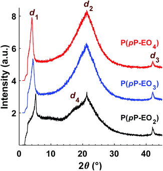
The morphology of the polymers in the P(pP-EOx) series was studied by wide angle X-ray scattering (WAXS) measurements, where the scattering intensity is monitored at an angle 2θ. Any (local) maximum indicates an ordered structure which repeats at a characteristic distance, d, according to Braggs law. As shown in Fig. 7, all polymers displayed similar scattering pattern. Scattering maxima were observed at low angles (2θ = 4–5°), which may correspond to the distance between two adjacent PpP stacks separated by the EO side chains (indicated as d1 in Fig. 8).19,38 Consequently this distance increased with increasing length of the side chain, from d1 = 1.7 nm (2θ = 5.2°) for P(pP-EO2), to 2.0 nm (2θ = 4.4°) and 2.2 nm (2θ = 4.0°) for P(pP-EO3) and P(pP-EO4), respectively. The larger difference in d between P(pP-EO2) and P(pP-EO3), than between P(pP-EO3) and P(pP-EO4), was likely due to a less efficient packing of the shorter EO side chains.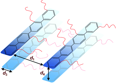 | ||
| Fig. 8 Schematic representation of the phase structure of P(pP-EOx) (d1 interchain distance, d3 width of PpP backbone, d4 interlayer distance) with the EOx side chains marked as red lines. | ||
At higher scattering angles (2θ = 21°, d2 = 0.4 nm) all polymers exhibited a broad peak. This type of amorphous halo is commonly observed scattering behavior of polymers, since all polymers exhibit a degree of short range order due to the covalent bonding in the molecule. This maximum was less broad for P(pP-EO2) indicating a higher degree of short-range ordering of the amorphous phase of this polymer, likely due to a lower number of possible conformations that the shorter EO side chains could attain.
At 2θ = 42° (d3 = 0.2 nm) a small peak was observed for all samples. This may correspond to the width of the PpP backbone chain (marked d3 in Fig. 8),40,41 which would further indicate an ordered arrangement of the PpP backbone chain. In comparison, the width of one phenyl ring in a graphene layer has been reported to be 0.25 nm.40
At lower angles (2θ = 18°), a small and broad shoulder was observed prior to the amorphous halo for P(pP-EO2). The shoulder may be related to the distance between two PpP layers, d4 = 0.5 nm. This is in agreement with Wegner et al., who estimated the distance between two neighboring PpP units in a stack to be around 0.53 nm.19
Upon addition of LiTFSI to P(pP-EO3) and P(pP-EO4), the intensity of all the scattering peaks decreased (Fig. 9), indicating less ordered structures in the electrolyte membranes, as compared to the neat polymers. Furthermore, the scattering angle of the low angle maxima decreased [to 2θ = 4.2° for P(pP-EO3) and 2θ = 3.9° for P(pP-EO4)]. This indicated a larger distance between two adjacent PpP stacks (d1 = 2.1 nm and 2.3 nm respectively), and the increase was likely caused by plasticization by the large TFSI anion. At the highest ionic concentration ([EO]/[Li] = 10), the low angle maxima were no longer observed, which might indicate that the ordering of adjacent PpP stacks was lost. Instead, electrolyte membranes exhibited maxima at 15.0° for P(pP-EO3) and 13.9° for P(pP-EO4), which corresponds to d4 = 0.59 and 0.64 nm, respectively. This may be related to the average distance between two PpP layers with TFSI anions incorporated in-between. The incorporation of TFSI anions between PpP layers would introduce defects in the layered structure thereby reducing the ordering.38 This may further explain the decrease in the transition enthalpies with increasing salt concentration, as observed by DSC. The incorporation of TFSI anions between the PpP layers has been suggested to improve the dissociation of the lithium salt and produce more mobile lithium ion speicies.38
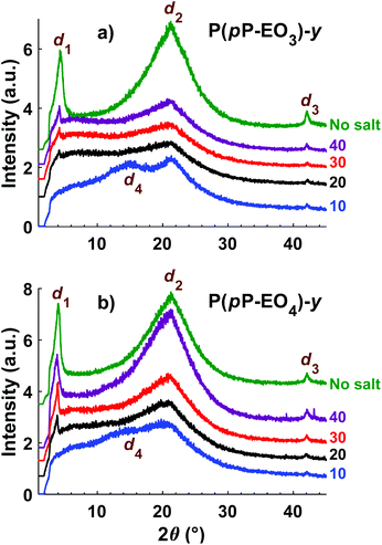 | ||
| Fig. 9 Diffractograms of the electrolyte membranes in the P(pP-EO3)-y (a) and P(pP-EO4)-y (b) series. | ||
3.5. Ionic conductivity
Electrochemical impedance spectroscopy was used to measure the temperature dependence of the ionic conductivity of the P(pP-EOx) membranes (Fig. 10). As expected, samples with high salt concentration exhibited a stronger temperature dependence due to the reduction of chain mobility of the side chains by the strong coordination with lithium ions. In the low temperature region, electrolytes with low ion concentration (i.e., high [EO]/[Li] values) exhibited the highest ionic conductivity. However, as the temperature (and hence chain mobility) increased, electrolytes with high ion concentration reached the highest conductivity. The membranes of P(pP-EO4) generally exhibited higher ionic conductivity than the P(pP-EO3) ones, because of the higher mobility of the longer EO chains in the former sample series. Furthermore, at a given value of [EO]/[Li], P(pP-EO4)-y contained more LiTFSI than P(pP-EO3)-y, leading to higher absolute charge carrier concentration. The influence of salt concentration on the ionic conductivity is shown in Fig. 11. As can be seen, the ionic conductivity reached an optimum at a certain salt concentration, which at 80 °C was [EO]/[Li] = 30 for P(pP-EO3) and [EO]/[Li] = 20 for P(pP-EO4). The optimum shifted towards higher ion concentration as the temperature increased. This effect was especially pronounced for P(pP-EO3)-10, most likely due to the combined effect of increased segmental chain motion and increased solvation of the LiTFSI as the temperature increased.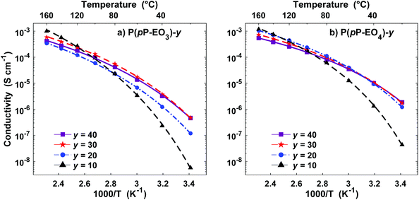 | ||
| Fig. 10 Arrhenius conductivity plots of the P(pP-EO3) (a) and P(pP-EO4) (b) electrolyte membranes containing LiTFSI (symbols are the measured data points and lines are calculated from the VTF-equation with the parameters shown in Table 2). | ||
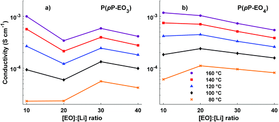 | ||
| Fig. 11 Ionic conductivity of the P(pP-EO3) (a) and P(pP-EO4) (b) membranes as a function of the ionic content (lines to guide the eye). | ||
The highest measured ionic conductivities at 20 °C in the series were 4.6 × 10⁻⁷ S cm−1 and 1.8 × 10⁻⁶ S cm−1 for P(pP-EO3)-30 and P(pP-EO4)-40, respectively. These values may be compared with those reported by Wegner et al. for polymer electrolytes based on LiTFSI and PpP backbone bearing two EO side chains on every second p-phenylene unit.19 At 20 °C, the ionic conductivity of these electrolytes reached values close to the present ones (∼2 × 10⁻⁶ S cm−1) with [EO]/[Li] = 25 and a 1![[thin space (1/6-em)]](https://www.rsc.org/images/entities/char_2009.gif) :
:![[thin space (1/6-em)]](https://www.rsc.org/images/entities/char_2009.gif) 1 ratio of PEO5 and PEO6 side chains. Moreover, the conductivity of P(pP-EO4)-20 was in level with that of a poly(styrene-block-ethylene oxide) (SEO) sample doped with LiTFSI, reaching conductivities between 7 × 10⁻⁷ and 4 × 10⁻⁶ S cm−1 at 20 °C.42,43
1 ratio of PEO5 and PEO6 side chains. Moreover, the conductivity of P(pP-EO4)-20 was in level with that of a poly(styrene-block-ethylene oxide) (SEO) sample doped with LiTFSI, reaching conductivities between 7 × 10⁻⁷ and 4 × 10⁻⁶ S cm−1 at 20 °C.42,43
At 80 °C the highest ionic conductivities observed were 5.5 × 10⁻⁵ S cm−1 for P(pP-EO3)-30 and 1.1 × 10⁻⁴ S cm−1 for P(pP-EO4)-20 (Fig. 10). These values are slightly higher than the ones measured by Wegner et al., reaching 10−4 S cm−1 at 100 °C.19 The conductivity of P(pP-EO4)-20 was also comparable to SEO doped with LiTFSI which have recorded conductivities between 3.5 × 10⁻⁴ and 5 × 10⁻⁴ S cm−1 at 90 °C.44,45 In another piece of work, Bergfelt et al. prepared triblock copolymers containing a oligo(ethylene oxide) methyl ether methacrylate center block and two benzyl methacrylate end blocks.46 After addition of LiTFSI, the electrolyte with [EO]/[Li] = 8 exhibited the highest ionic conductivity at 80 °C, 2 × 10⁻⁴ S cm−1. Moreover, Kuan and coworkers prepared tapered block copolymers of polystyrene and poly(oligo[ethylene oxide] methacrylate) doped with lithium triflate.47 At 80 °C the highest measured ionic conductivity was approximately 7 × 10⁻⁵ S cm−1.
In order to elucidate the underlying ion transport mechanism, the ionic conductivities of the present electrolyte membranes were fitted to the Vogel–Tamman–Fulcher (VTF) equation:
 | (1) |
The parameter T0 is often taken as Tg −50 K. However, apparent trends of the three parameters (Ea, T0, and σ0) can be heavily dependent on fitting method and choice of T0.48 Consequently, in this study T0 was included in the fitting through non-linear regression of the natural logarithm of the VTF equation (eqn (1)). The values of the fitted parameters are shown in Table 2, and conductivities calculated with the VTF-equation are indicated in Fig. 10. The apparent activation energy, Ea, is evaluated from conductivity data and is typically considered to include the activation energy for segmental mobility and ionic dissociation.48 The difference in Ea between the electrolyte membranes had limited statistical significance, but some trends could be discerned. As is typically observed, increasing ion concentration led to an increase in Ea, which is typically due to an increase in the level of coordination between lithium cations and EO impeding chain motions.48 Furthermore, the P(pP-EO4) membranes tended to have a lower Ea than P(pP-EO3), due to the longer and more flexible side chains. The Vogel temperature, T0, can be considered the thermodynamical glass transition temperature (free from kinetic effects) at which the polymer can only adopt one conformation.49–51 Just as in the case of Ea, T0 trended towards higher values with increasing salt concentration, but the differences in T0 were not statistically significant. Since the level of Li+–EO coordination increased with the salt concentration, the number of different conformations that the EO side chains can adopt decreases, causing T0 to increase. This effect was less pronounced in the electrolyte films of P(pP-EO4) due to the more flexible side chains. Furthermore, the difference between T0 and Tg increased with the salt concentration, as has previously been observed.48 For P(pP-EO3)-y (y = 40 and 30) this difference was 35 °C and increased to 48 and 72 °C for P(pP-EO3)-20 and P(pP-EO3)-10, respectively. For P(pP-EO4)-40, Tg − T0 was estimated to be 23 °C and increased to ∼35 °C upon further increase in salt concentration. This indicated that the kinetic effects when measuring the Tg by DSC are larger for the electrolyte membranes with shorter EOx side chains and higher salt concentration.
| Polymer | [EO]/[Li] | ln(σ0)a | E a (kJ mol−1) | T 0 (°C) | R 2 |
|---|---|---|---|---|---|
| a σ 0 in S cm−1. | |||||
| P( p P-EO3) | 40 | −3.3 ± 0.8 | 8.6 ± 1.9 | −71 ± 14 | 0.9994 |
| 30 | −2.9 ± 1.0 | 8.4 ± 2.2 | −66 ± 17 | 0.9991 | |
| 20 | −2.9 ± 0.4 | 9.6 ± 0.9 | −69 ± 6 | 0.9999 | |
| 10 | 0.014 ± 1.0 | 12.3 ± 2.2 | −58 ± 10 | 0.9995 | |
| P( p P-EO4) | 40 | −4.1 ± 0.3 | 6.4 ± 0.6 | −64 ± 5 | 0.9999 |
| 30 | −3.4 ± 0.2 | 7.1 ± 0.5 | −67 ± 5 | 0.9999 | |
| 20 | −2.8 ± 0.3 | 7.6 ± 0.6 | −64 ± 5 | 0.9999 | |
| 10 | −1.8 ± 0.6 | 8.3 ± 1.0 | −46 ± 6 | 0.9997 | |
Finally in the present study, we plasticized electrolyte membranes based on P(pP-EO3) by additions of triglyme in order to investigate the possibility to increase the ionic conductivity. Hence, P(pP-EO3)-20 containing 5 and 12 wt% triglyme and one membrane of P(pP-EO3)-30 with 10 wt% triglyme were prepared. The resulting membranes exhibited similar physical properties as the non-plasticized film; they were self-standing, flexible, and could be folded without being deformed. As expected, the triglyme additions significantly increased the ionic conductivity (Fig. 12). The increase was higher for P(pP-EO3)-20, most probably due to its higher salt concentration. At 80 °C, the membrane containing 12 wt% triglyme exhibited an ionic conductivity of 1.4 × 10⁻⁴ S cm−1 which represented a six-fold increase compared to the conductivity of the non-plasticized membrane.
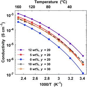 | ||
| Fig. 12 Arrhenius conductivity plots of P(pP-EO3)-20 (closed symbols) and P(pP-EO3)-30 membranes (open symbols) containing 0–12 wt% triglyme. | ||
4. Conclusions
We have explored salt-containing supramolecular assemblies of rigid-rod polymers tethered with flexible EOx side chains as ion-conducting solid electrolyte membranes with high dimensional stability. Long rigid PpP backbones bearing short flexible EOx side chains were successfully prepared through Yamamoto polymerization via in situ reduction of Ni(II). These polymers formed “molecular composite” morphology in which a soft EOx phase was mechanically reinforced by self-assembled stacks of PpP backbones. The materials showed order-to-disorder transition intervals up to 170 °C and were thermally stable up to ∼400 °C. After addition of salt, the resulting solid polymer electrolytes were found to retain the “molecular composite” morphology, albeit with a slightly lower degree of order. The order-to-disorder transition intervals increased up to 200 °C and an increase in the distance between adjacent PpP stacks was observed in relation to the corresponding salt-free samples. The ability to form thin self-standing membranes depended on both the EOx chain length (and hence EOx content) and the salt concentration and the highest conductivity reached by the present materials was 1.1 × 10⁻⁴ and 1.0 × 10⁻³ S cm−1 at 80 and 160 °C, respectively.Conflicts of interest
There are no conflicts to declare.Acknowledgements
We thank the Swedish Energy Agency for funding the project “High power density batteries using solid single-ion conducting polymer electrolytes” (project P40474-1) and the Royal Physiographic Society of Lund for financial support.References
- L. Long, S. Wang, M. Xiao and Y. Meng, J. Mater. Chem. A, 2016, 4, 10038–10069 RSC.
- L. Yue, J. Ma, J. Zhang, J. Zhao, S. Dong, Z. Liu, G. Cui and L. Chen, Energy Storage Mater., 2016, 5, 139–164 CrossRef.
- M. Armand, Solid State Ionics, 1983, 9–10, 745–754 CrossRef CAS.
- R. A. Zoppi, C. M. N. P. Fonseca, M.-A. De Paoli and S. P. Nunes, Solid State Ionics, 1996, 91, 123–130 CrossRef CAS.
- T. Mani and J. R. Stevens, Polymer, 1992, 33, 834–837 CrossRef CAS.
- P. V. Wright, Br. Polym. J., 1975, 7, 319–327 CrossRef CAS.
- D. E. Fenton, J. M. Parker and P. V. Wright, Polymer, 1973, 14, 589 CrossRef CAS.
- F. Bella, E. D. Ozzello, A. Sacco, S. Bianco and R. Bongiovanni, Int. J. Hydrogen Energy, 2014, 39, 3036–3045 CrossRef CAS.
- M.-A. De Paoli, A. F. Nogueira, D. A. Machado and C. Longo, Electrochim. Acta, 2001, 46, 4243–4249 CrossRef CAS.
- C. Monroe and J. Newman, J. Electrochem. Soc., 2005, 152, A396–A404 CrossRef CAS.
- P. Hovington, M. Lagacé, A. Guerfi, P. Bouchard, A. Mauger, C. M. Julien, M. Armand and K. Zaghib, Nano Lett., 2015, 15, 2671–2678 CrossRef CAS PubMed.
- A. Manthiram, X. Yu and S. Wang, Nat. Rev. Mater., 2017, 2, 16103 CrossRef CAS.
- D. G. Mackanic, X. Yan, Q. Zhang, N. Matsuhisa, Z. Yu, Y. Jiang, T. Manika, J. Lopez, H. Yan, K. Liu, X. Chen, Y. Cui and Z. Bao, Nat. Commun., 2019, 10, 5384 CrossRef PubMed.
- J. Sun, G. M. Stone, N. P. Balsara and R. N. Zuckermann, Macromolecules, 2012, 45, 5151–5156 CrossRef CAS.
- R. He and T. Kyu, Macromolecules, 2016, 49, 5637–5648 CrossRef CAS.
- B. Kim, C.-G. Chae, Y. Satoh, T. Isono, M.-K. Ahn, C.-M. Min, J.-H. Hong, C. F. Ramirez, T. Satoh and J.-S. Lee, Macromolecules, 2018, 51, 2293–2301 CrossRef CAS.
- D. T. Hallinan, S. A. Mullin, G. M. Stone and N. P. Balsara, J. Electrochem. Soc., 2013, 160, A464–A470 CrossRef CAS.
- N. S. Schauser, K. J. Harry, D. Y. Parkinson, H. Watanabe and N. P. Balsara, J. Electrochem. Soc., 2015, 162, A398–A405 CrossRef CAS.
- U. Lauter, W. H. Meyer and G. Wegner, Macromolecules, 1997, 30, 2092–2101 CrossRef CAS.
- G. Wegner, Thin Solid Films, 1992, 216, 105–116 CrossRef CAS.
- M. Ballauff, Angew. Chem., Int. Ed. Engl., 1989, 28, 253–267 CrossRef.
- B. R. Harkness and J. Watanabe, Macromolecules, 1991, 24, 6759–6763 CrossRef CAS.
- T. Yamamoto, Y. Hayashi and A. Yamamoto, Bull. Chem. Soc. Jpn., 1978, 51, 2091–2097 CrossRef CAS.
- T. Yamamoto and A. Yamamoto, Chem. Lett., 1977, 6, 353–356 CrossRef.
- I. Tonozuka, M. Yoshida, K. Kaneko, Y. Takeoka and M. Rikukawa, Polymer, 2011, 52, 6020–6028 CrossRef CAS.
- T. Oshima, M. Yoshizawa-Fujita, Y. Takeoka and M. Rikukawa, ACS Omega, 2016, 1, 939–942 CrossRef CAS PubMed.
- J. Ahn, R. Shimizu and K. Miyatake, J. Mater. Chem. A, 2018, 6, 24625–24632 RSC.
- Y. Zhang, J. Miyake, R. Akiyama, R. Shimizu and K. Miyatake, ACS Appl. Energy Mater., 2018, 1, 1008–1015 CrossRef CAS.
- H. Ghassemi and J. E. McGrath, Polymer, 2004, 45, 5847–5854 CrossRef CAS.
- J. Liu, P. D. Pickett, B. Park, S. P. Upadhyay, S. V. Orski and J. L. Schaefer, Polym. Chem., 2020, 11, 461–471 RSC.
- I. Colon and D. R. Kelsey, J. Org. Chem., 1986, 51, 2627–2637 CrossRef CAS.
- M. Yoshimoto, K. Honda, S. Kurosawa and M. Tanaka, J. Phys. Chem. C, 2014, 118, 16067–16073 CrossRef CAS.
- B. Chen, U. Baumeister, G. Pelzl, M. K. Das, X. Zeng, G. Ungar and C. Tschierske, J. Am. Chem. Soc., 2005, 127, 16578–16591 CrossRef CAS PubMed.
- P. Wittmeyer, S. Traser, R. Sander, K. B. Sondergeld, A. Ungefug, R. Weiss and M. Rehahn, Macromol. Chem. Phys., 2016, 217, 1473–1487 CrossRef CAS.
- J. L. Reddinger and J. R. Reynolds, Macromolecules, 1997, 30, 479–481 CrossRef CAS.
- S. E. Harding, Biophys. Chem., 1995, 55, 69–93 CrossRef CAS PubMed.
- L. H. Sperling, in Introduction to Physical Polymer Science, John Wiley & Sons, New Jersey, USA, 4th edn, 2005, pp. 114–116, DOI: DOI:10.1002/0471757128.ch1.
- U. Lauter, W. H. Meyer, V. Enkelmann and G. Wegner, Macromol. Chem. Phys., 1998, 199, 2129–2140 CrossRef CAS.
- S.-i. Nagae, H. M. Nekoomanesh, C. Booth and J. R. Owen, Solid State Ionics, 1992, 53–56, 1118–1124 CrossRef CAS.
- V. Petkov, A. Timmons, J. Camardese and Y. Ren, J. Phys.: Condens. Matter, 2011, 23, 435003 CrossRef PubMed.
- I. Karacan and L. Erzurumluoğlu, Fibers Polym., 2015, 16, 961–974 CrossRef CAS.
- W.-S. Young, J. N. L. Albert, A. B. Schantz and T. H. Epps III, Macromolecules, 2011, 44, 8116–8123 CrossRef CAS.
- M. Chintapalli, T. N. P. Le, N. R. Venkatesan, N. G. Mackay, A. A. Rojas, J. L. Thelen, X. C. Chen, D. Devaux and N. P. Balsara, Macromolecules, 2016, 49, 1770–1780 CrossRef CAS.
- M. Singh, O. Odusanya, G. M. Wilmes, H. B. Eitouni, E. D. Gomez, A. J. Patel, V. L. Chen, M. J. Park, P. Fragouli, H. Iatrou, N. Hadjichristidis, D. Cookson and N. P. Balsara, Macromolecules, 2007, 40, 4578–4585 CrossRef CAS.
- D. T. Hallinan, I. Villaluenga and N. P. Balsara, MRS Bull., 2018, 43, 759–767 CrossRef CAS.
- A. Bergfelt, L. Rubatat, D. Brandell and T. Bowden, Solid State Ionics, 2018, 321, 55–61 CrossRef CAS.
- W.-F. Kuan, R. Remy, M. E. Mackay and T. H. Epps III, RSC Adv., 2015, 5, 12597–12604 RSC.
- K. M. Diederichsen, H. G. Buss and B. D. McCloskey, Macromolecules, 2017, 50, 3831–3840 CrossRef CAS.
- G. Y. Gu, S. Bouvier, C. Wu, R. Laura, M. Rzeznik and K. M. Abraham, Electrochim. Acta, 2000, 45, 3127–3139 CrossRef CAS.
- G. Adam and J. H. Gibbs, J. Chem. Phys., 1965, 43, 139–146 CrossRef CAS.
- J. H. Gibbs and E. A. DiMarzio, J. Chem. Phys., 1958, 28, 373–383 CrossRef CAS.
Footnote |
| † Electronic supplementary information (ESI) available: 13C and HMQC NMR spectra of P(pP-EO3), molar mass distributions of the polymers, additional thermal data for neat polymers and electrolyte membranes, photographs of P(pP-EO2) films, frequency dependence of the ionic conductivity of the P(pP-EO3)-30 membrane. See DOI: 10.1039/d0py00115e |
| This journal is © The Royal Society of Chemistry 2020 |


