
 Open Access Article
 This Open Access Article is licensed under a Creative Commons Attribution-Non Commercial 3.0 Unported Licence
Optically detected magnetic resonance in CdSe/CdMnS nanoplatelets†
Danil O.
Tolmachev
*ab,
Vitalii Yu.
Ivanov
 *c,
Dmitri R.
Yakovlev
*ab,
Elena V.
Shornikova
a,
Bartłomiej
Witkowski
c,
Sushant
Shendre
d,
Furkan
Isik
e,
Savas
Delikani
de,
Hilmi Volkan
Demir
de and
Manfred
Bayer
ab
*c,
Dmitri R.
Yakovlev
*ab,
Elena V.
Shornikova
a,
Bartłomiej
Witkowski
c,
Sushant
Shendre
d,
Furkan
Isik
e,
Savas
Delikani
de,
Hilmi Volkan
Demir
de and
Manfred
Bayer
ab
aExperimentelle Physik 2, Technische Universität Dortmund, 44227 Dortmund, Germany. E-mail: danil.tolmachev@tu-dortmund.de; dmitri.yakovlev@tu-dortmund.de
bIoffe Institute, Russian Academy of Sciences, 194021 St. Petersburg, Russia
cInstitute of Physics, Polish Academy of Sciences, PL-02-668 Warsaw, Poland. E-mail: ivanov@ifpan.edu.pl
dLUMINOUS! Center of Excellence for Semiconductor Lighting and Displays, School of Electrical and Electronic Engineering, School of Physical and Materials Sciences, Nanyang Technological University, 639798 Singapore. E-mail: sd34@buffalo.edu
eDepartment of Electrical and Electronics Engineering, Department of Physics, UNAM – Institute of Materials Science and Nanotechnology, Bilkent University, 06800 Ankara, Turkey
First published on 26th October 2020
Abstract
Core/shell CdSe/(Cd,Mn)S colloidal nanoplatelets containing magnetic Mn2+ ions are investigated by the optically detected magnetic resonance technique, combining 60 GHz microwave excitation and photoluminescence detection. Resonant heating of the Mn spin system is observed. We identify two mechanisms of optical detection, via variation of either the photoluminescence polarization or its intensity in an external magnetic field. The spin–lattice relaxation dynamics of the Mn spin system is measured and used for evaluation of the Mn concentration. In CdSe/(Cd,Zn,Mn)S nanoplatelets the addition of Zn in the shells significantly broadens the magnetic resonance, evidencing local strain.
I. Introduction
Colloidal semiconductor nanocrystals (NCs) form an emerging class of nanostructures with a great variety of material compositions and shapes. Rather young members in the family of colloidal NCs are quasi-two-dimensional nanoplatelets (NPLs) with a thickness of a few monolayers only.1–5 The spin properties and magneto-optical effects in semiconductors can be greatly modified by implementing magnetic impurities, providing materials known as diluted magnetic semiconductors (DMSs).6,7 Among them the most popular are II–VI semiconductors, like (Cd,Mn)Te, (Cd,Mn)Se and (Zn,Mn)Se with Mn2+ magnetic ions. Doping with magnetic ions has been successfully realized for colloidal NCs, where the characteristic DMS properties have been observed for spherical quantum dots (QDs),8–14 nanoribbons,15,16 and NPLs.17–22Optically detected magnetic resonance (ODMR) is a powerful technique for investigating the electronic and spin structure of semiconductors and their nanostructures, for a review see ref. 24–26. It has been successfully applied to nanostructures, where it has an obvious advantage over the electron paramagnetic resonance (EPR) technique, whose sensitivity is typically insufficient. Optical detection is much more sensitive and in combination with spectral selectivity is well suited for state-selective nanostructure investigations,27,28 including colloidal nanocrystals.29–35 Also for low-dimensional diluted magnetic semiconductor heterostructures, ODMR has proven its power. We have shown, e.g., for (Zn,Mn)Se-based quantum wells,36 that the microwave-induced heating of the Mn spin system, both resonant and nonresonant, can be experimentally detected through several signatures in the photoluminescence (PL) spectra: (i) the shift of the energy of the emission line due to reducing the exciton giant Zeeman splitting, (ii) the degree of circular PL polarization in external magnetic field, and (iii) the emission intensity. Also the spin–lattice relaxation (SLR) dynamics of the Mn spin system can be measured via time-resolved PL detection after pulsed microwave excitation. Very recently, ODMR studies of DMS CdSe/(Cd,Mn)S core/shell nanoplatelets20,22 and nanorods23 have been reported. The measured dynamics of the ODMR signals has been related to the spin–lattice relaxation dynamics of the Mn2+ spin system and it has been suggested for evaluation of the Mn concentration.22
In this paper, we present optically detected magnetic resonance studies of core/shell CdSe/(Cd,Mn)S and CdSe/(Cd,Zn,Mn)S nanoplatelets. Resonant heating of the Mn spins by microwave radiation is detected. We identify two mechanisms, which provide the ODMR signals. The first one is measured by the reduction of the circular polarization degree under microwave radiation. It is provided by the decrease of the giant Zeeman splitting of excitons, when the Mn spin polarization is reduced. The second mechanism is measured by the decrease of the integral PL intensity being controlled by competition of radiative and nonradiative exciton recombination. Interestingly, the widths of the resonances are different for these two methods of detection. The relative contributions of these two mechanisms vary with Mn content. The polarization response dominates in the sample with the lowest Mn concentration, while the change in the PL intensity prevails in the nanoplatelets with the highest Mn content. The spin–lattice relaxation dynamics of the Mn spin system is measured, which we use as an experimental approach for the evaluation of the Mn concentration in the studied colloidal nanoplatelets.
Samples
Five samples of core–shell nanoplatelets were investigated. Details of their synthesis are given in ref. 4, 17 and 37 and section S3 in ESI.† All samples have a 2 monolayer thick CdSe core and 4 monolayer thick shells cladding the core. The nonmagnetic reference sample #0 contains CdSe/CdS nanoplatelets. The diluted magnetic semiconductor samples #1, #2 and #3 have Cd1−xMnxS shells with Mn concentrations of x = 0.009, 0.010 and 0.029, respectively. Sample #4 has a Cd0.9−xZn0.1MnxS shell with x = 0.010. The sample parameters are given in Table 1. Note that the Mn concentrations obtained by inductively coupled plasma mass spectrometry (ICP-MS) measurements differ from the values that we obtain from the spin–lattice relaxation dynamics (details are given below). We are convinced that the latter values are more relevant and will use them in the paper.
| Sample | PL maximum energy (eV) | PL FWHM (meV) | Mn content from ICP-MS, x | τ SLR (μs) | Mn content from ODMR, x | Γ (mT) | FWHM ΔPc (mT) | FWHM ΔI/I (mT) | B R (T) | g Mn |
|---|---|---|---|---|---|---|---|---|---|---|
| #0 CdSe/CdS | 2.127 | 70 | 0 | — | 0 | — | — | — | — | — |
| #1 CdSe/(Cd,Mn)S | 2.133 | 65 | 0.012 | 405 | 0.009 | 21 | 39 | 42 | 2.130 | 1.999 |
| #2 CdSe/(Cd,Mn)S | 2.139 | 75 | 0.019 | 350 | 0.010 | 25 | 40 | 44 | 2.139 | 1.991 |
| #3 CdSe/(Cd,Mn)S | 2.150 | 95 | 0.050 | 20 | 0.029 | 39 | 46 | 58 | 2.133 | 1.996 |
| #4 CdSe/(Cd,Zn,Mn)S | 2.184 | 78 | 0.010 | 370 | 0.010 | 51 | 71 | 120 | 2.132 | 1.997 |
Previously, we examined the CdSe/(Cd,Mn)S NPLs considered here by means of several magneto-optical techniques.22 We conclude that the photoluminescence is contributed by recombination of neutral (bright and dark) and charged excitons. The exchange interaction of neutral and charged excitons localized in the CdSe core with the magnetic Mn2+ ions in the shell was demonstrated. We showed that the exchange interaction is dominated by the hole (p–d exchange), whose wave function has about 30% penetration into the shells. The electron wave function has about 60% penetration, but the electron in conduction band has a considerably smaller exchange interaction integral (s–d exchange), compared to the hole in the valence band, which is typical for II–VI DMSs.6,7 We showed by time-resolved photoluminescence that the emission in the spectral range of 2.0–2.3 eV is due to neutral and charged excitons and has no contribution of the Mn emission.
II Experimental results
A Photoluminescence in magnetic field
Low temperature photoluminescence (PL) spectra of the studied DMS NPLs are shown in Fig. 1a. They are composed of a relatively broad emission band (full width at half maximum (FWHM) of 65–95 meV) with a low-energy tail, which is typical for ensembles of colloidal core/shell NPLs. The energies of the emission maxima of the different CdSe/(Cd,Mn)S NPLs are close to each other in the range of 2.127–2.150 eV, while the maximum for the CdSe/(Cd,Zn,Mn)S NPLs is shifted to higher energy (2.184 eV) due to the stronger quantum confinement provided by the higher barriers containing Zn. The PL peak positions and widths are listed in Table 1. | ||
| Fig. 1 (a) Photoluminescence spectra of CdSe/(Cd,Mn)S and CdSe/(Cd,Zn,Mn)S nanoplatelets: sample #1 (blue), #2 (green), #3 (red), and #4 (black). Excitation density 4 W cm−2, B = 0 T, and T = 1.8 K. (b) Degree of circular polarization as a function of magnetic field for the same samples. (c) Dependence of the integral PL intensity on magnetic field in CdSe/(Cd,Mn)S NPLs. Data are normalized to the PL intensity at zero magnetic field, I0. | ||
In external magnetic field applied in the Faraday geometry (parallel to the wavevector of the measured emission) the PL is circularly polarized. The degree of circular polarization (DCP) is defined as Pc = (I+ − I−)/(I+ + I−), where I+ and I− are the intensities of the σ+ and σ− circularly polarized PL components, respectively. Pc(B) increases linearly in weak fields up to 0.5 T, before it reaches saturation in high magnetic fields at the level Psatc (Fig. 1b). The polarization originates from the Zeeman splitting of the exciton states and reflects their different thermal populations.38
The DCP for neutral and charged excitons (trions) can be written as22,39,40
 | (1) |
Here ΔEZ(B) is the Zeeman splitting, kB is the Boltzmann constant, τ is the exciton lifetime and τs is the spin relaxation time. The saturation degree of polarization Psatc depends on the specifics of the spin level structure and the NPL orientation in the ensemble. In DMS structures, fast spin relaxation is provided by interaction with the magnetic ions, so that τ ≫ τs and the dynamical factor τ(τ + τs) ≈ 1. In DMS NPLs the Zeeman splitting is contributed by the intrinsic one, which is controlled by the exciton (trion) g-factor, and the additional term, Eexch(B), describing the exciton (trion) exchange interaction with the Mn2+ spins:
| ΔEZ(B) = gμBB + Eexch(B). | (2) |
Typically in DMSs the second term provides the giant Zeeman splitting, as at low temperatures Eexch(B) significantly exceeds the intrinsic splitting.6,7
The g-factor of the neutral dark exciton with angular momentum ±2 (which is the ground exciton state) is gXF = ge − 3gh = +3.8.22 Here ge = +1.70![[thin space (1/6-em)]](https://www.rsc.org/images/entities/char_2009.gif) 22,41,42 is the electron g-factor in CdSe/CdS NPLs and gh = −0.7 is the hole g-factor, measured in high magnetic fields.38 The exchange term is determined by the exchange interaction of the electron and the hole in the exciton with the Mn2+ ions, which are polarized by the external magnetic field. Therefore, it depends on the overlap of the electron and hole wave functions with the (Cd,Mn)S shells.
22,41,42 is the electron g-factor in CdSe/CdS NPLs and gh = −0.7 is the hole g-factor, measured in high magnetic fields.38 The exchange term is determined by the exchange interaction of the electron and the hole in the exciton with the Mn2+ ions, which are polarized by the external magnetic field. Therefore, it depends on the overlap of the electron and hole wave functions with the (Cd,Mn)S shells.
The negatively charged exciton (negative trion) is composed of two electrons in the singlet state and one hole. Its intrinsic Zeeman splitting is given by the hole g-factor and the exchange splitting by the hole penetration into the DMS shells. As we showed in ref. 22 and section S4 in ESI,† the DCP is negative in nonmagnetic CdSe/CdS NPLs, but positive in DMS NPLs due to the dominating contribution of the hole exchange interaction with the Mn2+ ions.
The integral PL intensity in CdSe/(Cd,Mn)S NPLs increases with magnetic field (Fig. 1c), and the increase is stronger for NPLs with higher Mn concentration reaching +12% at B = 3 T for sample #3. The intensity increase is also present in CdSe/(Cd,Zn,Mn)S NPLs, but absent in the nonmagnetic reference sample #0 (section S4 in ESI†). This increase is typical for bulk DMSs43 and was reported also for DMS quantum wells and quantum dots.44,45 It is explained by the magnetic-field-induced suppression of the spin-dependent Auger process, in which an exciton transfers its energy to a Mn2+ ion. The Auger suppression is related to the polarization of both the Mn2+ spins and the exciton spin by the magnetic field, resulting in relative spin configurations that are unfavorable for this process.
From the results presented in Fig. 1b and c one can see that the experimental information on the Mn spin polarization (and correspondingly the Mn spin temperature) can be received from the DCP and the integral PL intensity. Therefore, these characteristics can be used for ODMR detection, when the Mn spin system is resonantly heated by microwaves.
B ODMR signals
The ODMR study of the NPLs was performed using the technique described in ref. 36, where the microwave-induced variations of the PL spectra (for both circularly polarized components) are recorded as functions of magnetic field (Methods). The ODMR spectra are presented as changes of normalized PL intensity
Here I±(E) is the intensity of the unperturbed PL spectrum and I±MW(E) is the PL intensity under microwave excitation (for the σ+ and σ− circular polarized components), E is PL photon energy.
Fig. 2 shows detailed ODMR studies performed with the microwave at frequency of 59.6 GHz on sample #1. For the other samples, see ESI† (Fig. S1–S3†). The microwave-induced changes of the σ+ and σ− PL components are shown in Fig. 2a and b, respectively. Here, the vertical axis denotes the photon energy and the horizontal axis gives the magnetic field. The data shown by the color scale are the differences between the PL intensities without and with microwave irradiation ΔI± = I±MW − I±, normalized on the PL intensity I±. In both panels a colored signal appears in around BR ≈ 2.130 T, corresponding to the magnetic resonance of the Mn2+ ions. The blue color for the σ+ polarized component means that the PL signal decreases under microwave radiation. Vice versa, the red color for the σ− polarized component indicates the PL increase. This is the effect expected for the DCP, as the polarization degree is positive (I+ > I−) without microwaves, and the microwave heating results in a decrease on the Mn spin polarization and, thus, of the DCP. This is additionally illustrated in Fig. 2c, where

 | ||
| Fig. 2 (a) and (b) Microwave induced variation of σ− and σ+ components of the PL intensity in sample #1 as a function of magnetic field. T = 1.8 K, microwave frequency ν = 59.6 GHz. Arrows show position of the PL maximum. (c) Microwave-induced change of degree of circular polarization (ΔPc). (d) Microwave-induced change of total PL intensity. (e) ΔPc as a function of magnetic field at the PL maximum of 2.133 eV. (f) ODMR detected through the total PL intensity at 2.133 eV. Spectral dependence of ODMR signals detected via degree of circular polarization (g) and total PL intensity (h) at the resonance field of BR = 2.130 T. Blue line shows PL spectrum. | ||
We showed earlier that in (Zn,Mn)Se-based quantum wells the ODMR can be detected not only via the DCP, but also via the total PL intensity,36 which is the sum of both circularly polarized PL components I = I+ + I−. We find that this is also possible for DMS NPLs. In order to highlight this and present it separately from the DCP changes, we plot in Fig. 2d the normalized total PL intensity variation:
The blue color indicates a signal decrease. It is expected as the Mn heating corresponds to an effective decrease of the external magnetic field in the I(B) dependence, compare with Fig. 1c.
Resonance profiles of the DCP and PL intensity variations for fulfilling the ODMR conditions at energy of the PL maximum are plotted in Fig. 2e and f, respectively. Their parameters will be discussed below. In Fig. 2g and h we show the spectral dependences of the two effects detected at the resonance field of BR = 2.130 T. The maximal changes occur at the PL maximum and they are decreasing smoothly towards the low energy tail. At the high energy side the variation of the PL intensity drops abruptly. We checked that it cannot be related to the giant Zeeman splitting, as for that signal already very small shifts of <0.1 meV are sufficient. It seems that the observed change is due to some redistribution of intensity within the PL band, i.e. within the NPL ensemble. Among possible mechanisms one may suggest the redistribution among trion and exciton emission and modification of energy transfer (Förster energy transfer) within the NPL ensemble.
In general, all four studied DMS NPL samples demonstrate the similar behavior (compare Fig. 2 and Fig. S1–S3†). The ODMR resonances appear both in the polarization and PL intensity responses, but their relative amplitudes vary from sample to sample. This is illustrated in Fig. 3a, where the microwave induced variations of the σ− polarized PL component are compared for samples #1 (x = 0.009) and #3 (x = 0.029). The two signals have opposite signs: ΔI−/I− is positive for sample #1, which is due to the dominating polarization response, while it is negative for sample #3 due to the prevailing response in the PL intensity.
 | ||
| Fig. 3 (a) Microwave induced variation of σ− PL component as a function of magnetic field for samples #1 (blue) and #3 (red) at the PL peak position. In sample #1 with lower Mn concentration the intensity of the σ− component increases at resonance, while in sample #3 with higher Mn concentration it decreases. (b and c) Lineshapes of the ODMR resonances recorded via the degree of circular polarization (b) and the total PL intensity (c). The resonance amplitudes are normalized and the signals are shifted vertically for clarity. Magnetic fields are given relative to the resonance, i.e. the zero at the bottom axis corresponds to the resonance field BR. (d) Comparison of individual linewidths Γ of ODMR resonances for U+000A CdSe/(Cd,Mn)S NPLs (closed circles, color code is the same as in other panels) and for CdSe/(Cd,Zn,Mn)S NPLs (open circle) with Zn1−xMnxSe/(Zn,Be)Se quantum wells (open squares), see section S2 in ESI.† | ||
Fig. 3b and c show the ODMR resonances for all studied samples, monitored via the variations of DCP and total PL intensity, respectively. The hyperfine level structure of the Mn2+ spin resonance is not resolved, as expected considering the relatively high Mn concentrations of the studied samples, see for example ref. 46, where only the envelope of the Mn fine and hyperfine structure could be observed. The ODMR resonance may be broadened due to NPL size fluctuations or dipole–dipole interaction between the Mn spins. Also variations of local strain in the thin DMS shells may provide broadening.
The localized spins of Mn2+ ions in magnetic field can be described by the spin Hamiltonian
| Ĥs = gMnμBBS + SDS + ASI |
In the CdSe/(Cd,Mn)S NPLs the linewidth increases with increasing Mn concentration. Interestingly, the resonance widths differ for the DCP and PL intensity resonances, while they are expected to be the same being controlled by the properties of the Mn spin system only. The difference is about 10–20% for the CdSe/(Cd,Mn)S NPLs, but reaches about a factor of two in the CdSe/(Cd,Zn,Mn)S NPLs (see Table 1 and Fig. S3e, f†). We checked that this is not due to the spectral dependence of the resonance shape, as the ODMR signals have a smooth spectral dependence in the energy range below the PL maximum. We suggest that an additional nonlinear effect, whose origin needs to be identified, is responsible for that.
Sample #4 with (Cd,Zn,Mn)S shells exhibits the broadest ODMR contour with the FWHM of 71 mT and Γ = 51 mT (shown in Fig. 3d with an open circle), although its Mn content is x = 0.01, i.e. a Γ value comparable to those for samples #1 and #2 is expected. This finding can be explained by the presence of axial strain in the (Cd,Zn,Mn)S shells, which results in a finite zero-field splitting value D, different from the one in (Cd,Mn)S. Note that for the ensemble of randomly oriented nanoplateletes it is difficult to provide an estimate of the D constant from the resonance width. Interestingly, sample #4 with Zn in the shell demonstrates about an order of magnitude larger ODMR signals compared to the CdSe/(Cd,Mn)S NPLs (Fig. S3†).
Table 1 contains also information on the resonance fields BR and the evaluated g-factors gMn for the applied microwave frequency of ν = 59.6 GHz. The gMn values are close to 2.01 as established for the Mn2+ ions in II–VI DMSs.6,7
C Spin–lattice relaxation dynamics of the Mn spin system
One can implement in the ODMR technique time-resolved detection of the microwave-induced changes.32–34,36,50 For that, the dynamics of the changes in either DCP or PL intensity can be measured. We performed corresponding experiments for all studied samples and show in Fig. 4a the time evolution of the relative changes of PL intensity after a microwave pulse. The relaxation dynamics is determined by cooling of the Mn spin system via spin–lattice relaxation (SLR). The SLR time, τSLR, is in the range between 350 and 405 μs in samples #1, #2 and #4, but is much shorter, only 20 μs, in sample #3 (Table 1).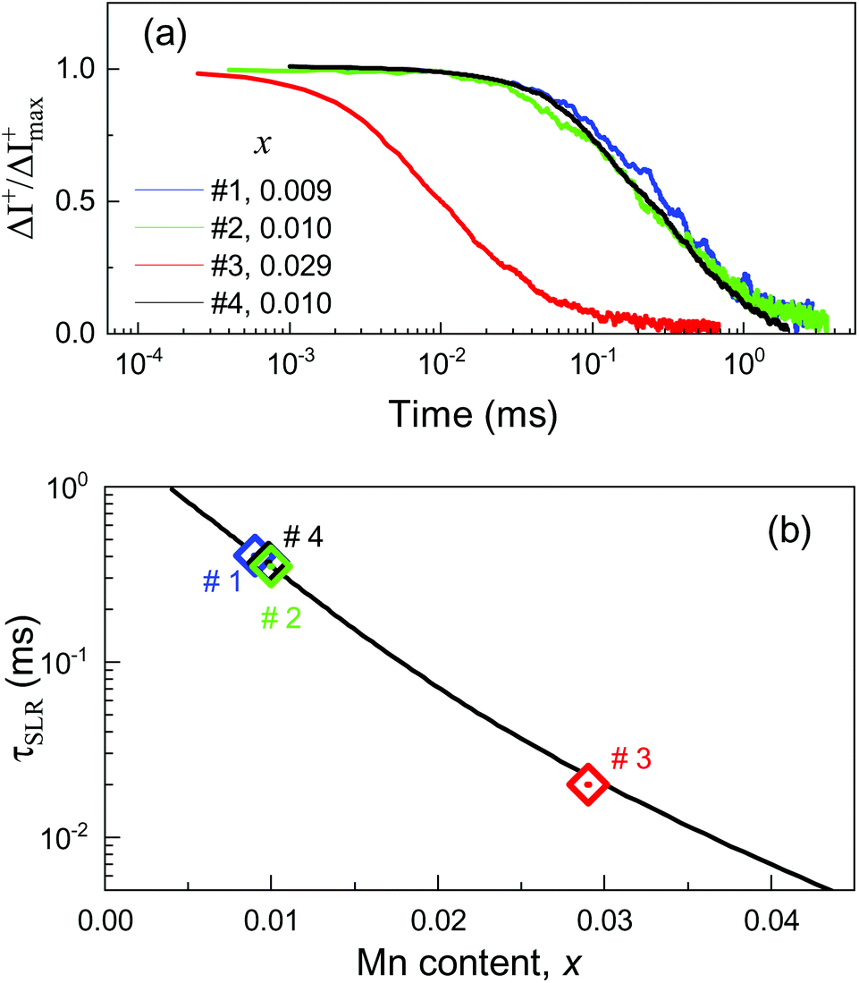 | ||
| Fig. 4 (a) σ+ PL component evolution after switching off the microwave radiation. (b) Spin–lattice relaxation times versus Mn content. Line: reference data adapted from ref. 50, symbols: present study, the data points are placed on the line according to the measured τSLR (Table 1). | ||
It is known that the τSLR of Mn2+ ions in II–VI semiconductors follows a very strong dependence on the Mn concentration x, which covers about five orders of magnitude from 1 ms down to 10 ns with increasing x from 0.004 up to 0.11, see Fig. 8.10 in ref. 50. In Fig. 4b we show by the black line an interpolated dependence based on the experimental data at T = 1.6 K, collected in ref. 50. This strong dependence arises from the fact that an isolated Mn2+ ion does not couple to the phonon system and the SLR dynamics is controlled by the Mn–Mn interactions. The strong dependence τSLR(x) can serve as a precise benchmark for the evaluation of the Mn concentration. It is especially interesting for our structures, where direct measurement of the giant Zeeman splitting is not possible. In Fig. 4b we place the experimental data points on the black line, according to the τSLR values, and evaluate the Mn content. As one can see from Table 1, the nominal Mn concentrations measured by the ICP-MS method are in good agreement with our data for samples #1 and #4, but differ clearly for samples #2 and #3.
III Conclusion
In summary, we have performed detailed ODMR studies of CdSe/(Cd,Mn)S and CdSe/(Cd,Zn,Mn)S nanoplatelets containing magnetic Mn2+ ions. Two signatures of ODMR detection known from diluted magnetic semiconductor quantum wells are approved also for the nanoplatelets. They are related to the resonant microwave heating of the Mn2+ spins detected via changes of the PL polarization or PL intensity. The spin–lattice relaxation dynamics measured in time-resolved ODMR allows us to evaluate the Mn concentration by the approach not involving the giant Zeeman splitting of excitons. Being combined with the direct measurements of the exciton giant Zeeman splitting, e.g., via magneto-absorption or magnetic circular dichroism, it would allow one to measure the modification of the carrier–Mn exchange integrals in the strongly confinement regimes. The ODMR technique can be readily used for the samples with different Mn distribution, e.g., in core only or with various Mn concentrations in core and shell.IV Methods
The ODMR spectrometer used for the current study is based on an all solid-state microwave oscillator/scalar analyzer (G4-602E module produced by the ELMIKA Company) with a tuning range of 59.05–60.55 GHz (0.248 meV photon energy) and a maximal output power of 140 mW. The oscillator can operate in cw mode or in periodically pulsed mode with a maximum frequency of 30 MHz, a transition time of the microwave pulse of less than 4 ns, and 60 dB damping level during blanking. The sample is placed in a cylindrical TE011 type tunable microwave cavity with a Q-factor varied in the 600–2500 range. The typical effective induction of the magnetic component of the microwave field is B1 = 0.13 mT. The microwave transmission system is based on a rectangle waveguide equipped with a variable attenuator with a maximum attenuation level of 40 dB. The microwave cavity has two pairs of orthogonal apertures with conic cross sections for optical access with a numerical aperture of NA = 0.2. The cavity with the sample was mounted in the variable temperature insert of an Oxford Instruments magnetic cryostat, type SM-4000. The ODMR measurements were performed at a temperature of T = 1.8 K with the sample immersed in superfluid helium. Magnetic fields up to 3 T were applied in the Faraday geometry.The sample in the cavity was excited by a 405 nm semiconductor laser (photon energy 3.06 eV) with 0.5 mW power, focused into a spot with a diameter of 400 μm. In the continuous wave regime the density of photoexcitation is kept at a low level of 4 mW cm−2, in order to minimize additional heating of the Mn spin system. The PL emission was collected in back scattering geometry and dispersed by a 0.5 m Cherny–Turner grating spectrometer, equipped for detection with a Hamamatsu charge-coupled-device (CCD) camera operating in the fast frame transfer (FFT) mode and synchronized with the microwave excitation pulse train switching (typical microwave switching period of 100 ms). The magnetic-field dependences for ODMR are obtained by scanning the field with a small step of 1 mT and recording full spectra of photoluminescence and microwave induced changes of the photoluminescence at each magnetic field value.
The time-resolved ODMR measurements were provided using a time-correlated single-photon counting technique (TCSPC). A low-noise avalanche photodiode module, type PDM from Micro Photon Device Company, was used in combination with a MSA-6A (FAST Comtech) TCSPC multichannel analyzer. The temporal resolution of this combination was about 30 ns. During the time-resolved ODMR measurements the photoluminescence was excited with a continuous wave laser, while the microwave power was modulated with 100–1000 Hz frequency.
The studied NPLs were synthesized by colloidal chemistry, the details are given in section S3 in ESI.† For the ODMR experiments they were drop-casted on substrates. For better adhesion, the NPLs were deposited on the (001) surface of Si plates with 4 × 1 × 0.3 mm3 dimension, decorated by ZnO nanorods.
Conflicts of interest
There are no conflicts to declare.Acknowledgements
This work was supported by the Deutsche Forschungsgemeinschaft in the frame of the International Collaborative Research Centre TRR 160 (Projects B1 and C7). D. R. Y. acknowledges partial support of the Russian Science Foundation (Project 20-42-01008). V. Yu. I. acknowledges support of the Polish National Science Center (Grant No. 2018/30/M/ST3/00276). H. V. D. gratefully acknowledges the financial support in part from Singapore National Research Foundation under the programs of NRF-NRFI2016-08. H. V. D. also acknowledges support from TUBA.References
- S. Ithurria and B. Dubertret, J. Am. Chem. Soc., 2008, 130, 16504–16505 CrossRef CAS.
- Z. Li and X. Peng, J. Am. Chem. Soc., 2011, 133, 6578–6586 CrossRef CAS.
- M. D. Tessier, C. Javaux, I. Maksimovic, V. Loriette and B. Dubertret, ACS Nano, 2012, 6, 6751–6758 CrossRef CAS.
- S. Delikanli, G. Yu, A. Yeltik, S. Bose, T. Erdem, J. Yu, O. Erdem, M. Sharma, V. K. Sharma, U. Quliyeva, S. Shendre, C. Dang, D. H. Zhang, T. C. Sum, W. Fan and H. V. Demir, Adv. Funct. Mater., 2019, 29, 1901028 CrossRef.
- M. Sharma, S. Delikanli and H. V. Demir, Proc. IEEE, 2020, 108, 655–675 Search PubMed.
- J. K. Furdyna, J. Appl. Phys., 1988, 64, R29–R64 CrossRef CAS.
- Introduction to the Physics of Diluted Magnetic Semiconductors, ed. J. Kossut and J. A. Gaj, Springer-Verlag, Berlin, 2010 Search PubMed.
- P. I. Archer, S. A. Santangelo and D. R. Gamelin, Nano Lett., 2007, 7, 1037–1043 CrossRef CAS.
- R. Beaulac, P. I. Archer, X. Liu, S. Lee, G. M. Salley, M. Dobrowolska, J. K. Furdyna and D. R. Gamelin, Nano Lett., 2008, 8, 1197–1201 CrossRef CAS.
- D. A. Bussian, S. A. Crooker, M. Yin, M. Brynda, Al. L. Efros and V. I. Klimov, Nat. Mater., 2009, 8, 35–40 CrossRef CAS.
- R. Fainblat, C. J. Barrows, E. Hopmann, S. Siebeneicher, V. A. Vlaskin, D. R. Gamelin and G. Bacher, Nano Lett., 2016, 16, 6371–6377 CrossRef CAS.
- W. D. Rice, W. Liu, T. A. Baker, N. A. Sinitsyn, V. I. Klimov and S. A. Crooker, Nat. Nanotechnol., 2016, 11, 137–142 CrossRef CAS.
- W. D. Rice, W. Liu, V. Pinchetti, D. R. Yakovlev, V. I. Klimov and S. A. Crooker, Nano Lett., 2017, 17, 3068–3075 CrossRef CAS.
- W. Zheng, Z. Wang, J. Wright, B. Goundie, N. S. Dalal, R. W. Meulenberg and G. F. Strouse, J. Phys. Chem. C, 2011, 115, 23305–23314 CrossRef CAS.
- J. H. Yu, X. Liu, K. E. Kweon, J. Joo, J. Park, K.-T. Ko, D. W. Lee, S. Shen, K. Tivakornsasithorn, J. S. Son, J.-H. Park, Y.-W. Kim, G. S. Hwang, M. Dobrowolska, J. K. Furdyna and T. Hyeon, Nat. Mater., 2010, 9, 47–53 CrossRef CAS.
- R. Fainblat, J. Frohleiks, F. Muckel, J. H. Yu, J. Yang, T. Hyeon and G. Bacher, Nano Lett., 2012, 12, 5311–5317 CrossRef CAS.
- S. Delikanli, M. Z. Akgul, J. R. Murphy, B. Barman, Y. Tsai, T. Scrace, P. Zhang, B. Bozok, P. L. Hernández-Martínez, J. Christodoulides, A. N. Cartwright, A. Petrou and H. V. Demir, ACS Nano, 2015, 9, 12473–12479 CrossRef CAS.
- F. Muckel, S. Delikanli, P. L. Hernández-Martínez, T. Priesner, S. Lorenz, J. Ackermann, M. Sharma, H. V. Demir and G. Bacher, Nano Lett., 2018, 18, 2047–2053 CrossRef CAS.
- A. H. Davis, E. Hofman, K. Chen, Z.-J. Li, A. Khammang, H. Zamani, J. M. Franck, M. M. Maye, R. W. Meulenberg and W. Zheng, Chem. Mater., 2019, 31, 2516–2523 CrossRef CAS.
- R. Strassberg, S. Delikanli, Y. Barak, J. Dehnel, A. Kostadinov, G. Maikov, P. L. Hernández-Martínez, M. Sharma, H. V. Demir and E. Lifshitz, J. Phys. Chem. Lett., 2019, 10, 4437–4447 CrossRef CAS.
- A. Najafi, S. Tarasek, S. Delikanli, P. Zhang, T. Norden, S. Shendre, M. Sharma, A. Bhattacharya, N. Taghipour, J. Pientka, H. V. Demir, A. Petrou and T. Thomay, ACS Appl. Nano Mater., 2020, 3, 3151–3156 CrossRef CAS.
- E. V. Shornikova, D. R. Yakovlev, D. O. Tolmachev, V. Yu. Ivanov, I. V. Kalitukha, V. F. Sapega, D. Kudlacik, Yu. G. Kusrayev, A. A. Golovatenko, S. Shendre, S. Delikanli, H. V. Demir and M. Bayer, ACS Nano, 2020, 14, 9032–9041 CrossRef CAS.
- J. Dehnel, Y. Barak, I. Meir, A. K. Budniak, A. P. Nagvenkar, D. R. Gamelin and E. Lifshitz, ACS Nano, 2020 DOI:10.1021/acsnano.0c05454.
- B. C. Cavenett, Adv. Phys., 1981, 30, 475–538 CrossRef CAS.
- P. G. Baranov and N. G. Romanov, Appl. Magn. Reson., 2001, 21, 165–193 CrossRef CAS.
- P. G. Baranov, H. J. von Bardeleben, F. Jelezko and J. Wrachtrup, Magnetic Resonance of Semiconductors and Their Nanostructures: Basic and Advanced Applications, Springer, Wien, 2017 Search PubMed.
- C. Y. Hu, W. Ossau, D. R. Yakovlev, G. Landwehr, T. Wojtowicz, G. Karczewski and J. Kossut, Phys. Rev. B: Condens. Matter Mater. Phys., 1998, 58, R1766 CrossRef CAS.
- V. Yu. Ivanov, T. S. Shamirzaev, D. R. Yakovlev, A. K. Gutakovskii, L. Owczarczyk and M. Bayer, Phys. Rev. B: Condens. Matter Mater. Phys., 2018, 97, 245306 CrossRef CAS.
- E. Lifshitz, I. D. Litvin, H. Porteanu and A. A. Lipovskii, Chem. Phys. Lett., 1998, 295, 249–256 CrossRef CAS.
- E. Lifshitz, I. Dag, I. D. Litvitn and G. Hodes, J. Phys. Chem. B, 1998, 102, 9245–9250 CrossRef CAS.
- E. Lifshitz, A. Glozman, I. D. Litvin and H. Porteanu, J. Phys. Chem. B, 2000, 104, 10449–10461 CrossRef CAS.
- L. Langof, E. Ehrenfreund, E. Lifshitz, O. I. Micic and A. J. Nozik, J. Phys. Chem. B, 2002, 106, 1606–1612 CrossRef CAS.
- K. J. van Schooten, J. Huang, W. J. Baker, D. V. Talapin, C. Boehme and J. M. Lupton, Nano Lett., 2013, 13, 65–71 CrossRef CAS.
- K. J. van Schooten, J. Huang, D. V. Talapin, C. Boehme and J. M. Lupton, Phys. Rev. B: Condens. Matter Mater. Phys., 2013, 87, 125412 CrossRef.
- G. Yu. Rudko, I. P. Vorona, V. I. Fediv, A. Kovalchuk, J. E. Stehr, B. D. Shanina, W. M. Chen and I. A. Buyanova, Nanoscale Res. Lett., 2017, 12, 130 CrossRef.
- V. Yu. Ivanov, M. Godlewski, D. R. Yakovlev, M. K. Kneip, M. Bayer, S. M. Ryabchenko and A. Waag, Phys. Rev. B: Condens. Matter Mater. Phys., 2008, 78, 085322 CrossRef.
- S. Shendre, S. Delikanli, M. Li, D. Dede, Z. Pan, S. T. Ha, Y. H. Fu, P. L. Hernández-Martínez, J. Yu, O. Erdem, A. I. Kuznetsov, C. Dang, T. C. Sum and H. V. Demir, Nanoscale, 2019, 11, 301–310 RSC.
- E. V. Shornikova, L. Biadala, D. R. Yakovlev, D. Feng, V. F. Sapega, N. Flipo, A. A. Golovatenko, M. A. Semina, A. V. Rodina, A. A. Mitioglu, M. V. Ballottin, P. C. M. Christianen, Yu. G. Kusrayev, M. Nasilowski, B. Dubertret and M. Bayer, Nano Lett., 2018, 18, 373–380 CrossRef CAS.
- F. Liu, L. Biadala, A. V. Rodina, D. R. Yakovlev, D. Dunker, C. Javaux, J. P. Hermier, Al. L. Efros, B. Dubertret and M. Bayer, Phys. Rev. B: Condens. Matter Mater. Phys., 2013, 88, 035302 CrossRef.
- F. Liu, A. V. Rodina, D. R. Yakovlev, A. Greilich, A. A. Golovatenko, A. S. Susha, A. L. Rogach, Yu. G. Kusrayev and M. Bayer, Phys. Rev. B: Condens. Matter Mater. Phys., 2014, 89, 115306 CrossRef.
- D. Kudlacik, V. F. Sapega, D. R. Yakovlev, I. V. Kalitukha, E. V. Shornikova, A. V. Rodina, E. L. Ivchenko, G. S. Dimitriev, M. Nasilowski, B. Dubertret and M. Bayer, Nano Lett., 2020, 20, 517–525 CrossRef CAS.
- D. Feng, D. R. Yakovlev, B. Dubertret and M. Bayer, Charge separation dynamics in CdSe/CdS core/shell nanoplatelets addressed by coherent electron spin precession, ACS Nano, 2020, 14, 7237–7244 CrossRef CAS.
- M. Nawrocki, Yu. G. Rubo, J. P. Lascaray and D. Coquillat, Phys. Rev. B: Condens. Matter Mater. Phys., 1995, 52, R2241 CrossRef CAS.
- D. O. Tolmachev, R. A. Babunts, N. G. Romanov, P. G. Baranov, B. R. Namozov, Yu. G. Kusrayev, S. Lee, M. Dobrowolska and J. K. Furdyna, Phys. Status Solidi B, 2010, 247, 1511–1513 CrossRef CAS.
- A. V. Chernenko, P. S. Dorozhkin, V. D. Kulakovskii, A. S. Brichkin, S. V. Ivanov and A. A. Toropov, Phys. Rev. B: Condens. Matter Mater. Phys., 2005, 72, 045302 CrossRef.
- D. O. Tolmachev, A. S. Gurin, N. G. Romanov, A. G. Badalyan, R. A. Babunts, P. G. Baranov, B. R. Namozov and Yu. G. Kusrayev, JETP Lett., 2012, 96, 247–251 CrossRef.
- R. S. Title, Phys. Rev., 1963, 131, 2503–2504 CrossRef CAS.
- R. S. Title, Study of electron paramagnetic resonance, in Physics and Chemistry of II-VI Compounds, ed. M. Aven and J. S. Prener, Amsterdam, North Holland, 1967 Search PubMed.
- M. Inoue, J. Phys. Soc. Jpn., 1972, 33, 1024–1030 CrossRef CAS.
- D. R. Yakovlev and I. A. Merkulov, Spin and energy transfer between carriers, magnetic ions, and lattice, in Introduction to the Physics of Diluted Magnetic Semiconductors, ed. J. Kossut and J. A. Gaj, Springer-Verlag, Berlin, 2010, pp. 263–303 Search PubMed.
Footnote |
| † Electronic supplementary information (ESI) available: Additional experimental data on ODMR and polarization in sample #0, synthesis details. See DOI: 10.1039/D0NR05633B |
| This journal is © The Royal Society of Chemistry 2020 |