
 Open Access Article
 This Open Access Article is licensed under a Creative Commons Attribution-Non Commercial 3.0 Unported Licence
Shape control of soft patchy nanoparticles under confinement
Ivonne Elizabeth
Ventura Rosales
 *a,
Lorenzo
Rovigatti
b,
Emanuela
Bianchi
cd,
Christos N.
Likos
a and
Emanuele
Locatelli
ac
*a,
Lorenzo
Rovigatti
b,
Emanuela
Bianchi
cd,
Christos N.
Likos
a and
Emanuele
Locatelli
ac
aFaculty of Physics, University of Vienna, Bolzmanngasse 5, A-1090 Vienna, Austria. E-mail: ivonne.ventura.rosales@univie.ac.at; christos.likos@univie.ac.at; emanuele.locatelli@univie.ac.at
bDipartimento di Fisica, Sapienza Università di Roma, Stanza 103, Edificio Fermi, 00185 Roma, Italy. E-mail: lorenzo.rovigatti@uniroma1.it
cInstitut für Theoretische Physik, TU Wien, Wiedner Hauptstraße 8-10, A-1040 Wien, Austria. E-mail: emanuela.bianchi@tuwien.ac.at
dCNR-ISC, Uos Sapienza, Piazzale A. Moro 2, 00185 Roma, Italy
First published on 5th October 2020
Abstract
Molecular building blocks undergoing a hierarchical assembly process form nano-scale objects which can further assemble into supramolecular structures. When the intermediate units have a limited valence in bonding, complex structures with tailored properties can be created. Here, we consider a composite, star-shaped particle made of f diblock copolymer chains uniformly grafted on a spherical colloid and investigate its first self-assembly stage both in the bulk and under lateral confinement. By means of numerical simulations, we show that, in the bulk, this system develops aggregates whose number and size depend on the temperature as well as on the relative ratio of solvophobic monomers. The emerging aggregates are referred to as patches and impart directionality in bonding to the complex particle. We further characterize how we can control, by changing the lateral confinement, the shape of the brush and the patch properties as a function of the distance between the confining walls. We find that the number of the patches can be determined by tuning the degree of confinement imposed on the particle. Finally, we employ a continuum mechanics model, known as the Liquid Drop Model, to gain insight into the elastic properties of the system. This theoretical approach allows to connect the patch properties to the elastic response of the composite particle.
1. Introduction
The present-day paradigm for material design relies on self-assembly, a spontaneous process taking place at equilibrium, where building blocks arrange to form complex structures.1 Within this paradigm, the design of the building units is crucial to guarantee a reliable self-assembly of the desired target structures.2,3 Patchy particles emerged, more than a decade ago, as embodiment of a smart design rule: inspired by the chemical assembling principles at the molecular level, these particles stood out as successful nano- and meso-scale units for the fabrication of novel materials. Patchy particles, also referred to as “colloidal molecules”, are entities of colloidal size, whose surface is decorated by attractive spots, giving rise to effective anisotropic interactions.4–6 From a theoretical standpoint, patchy particles display remarkable thermodynamic properties in the bulk as well as close to surfaces;7–12 their promising features triggered great efforts to synthesize patchy units at the micron scale. Unfortunately, limitations in the synthesis of patchy colloids have been for quite a long time the greatest bottleneck for their application in materials science.In the last few years, two novel bottom-up routes for the synthesis of conventional patchy particles have been explored: all-DNA based13–18 and polymer based19–22 units. Notably, both are examples of soft, deformable particles, formed via a self-assembly process, whose properties are temperature-dependent. All-DNA particles consist of short (10–100 nucleotides) single DNA strands, designed to form, upon lowering the temperature, stable supra-molecular aggregates or bulk phases.13,16,18 All-DNA colloids provide bio-compatible materials and self-assemble in the bulk with high yield, thus overcoming the limitations of most synthesis techniques for conventional patchy colloids. The downsides of DNA building blocks comes from the limited temperature range, due to DNA's length-dependent melting point, and from the necessity of optimizing the synthetic sequences through a tedious trial-and-error procedure.
Polymer-based patchy particles are the result of the self-assembly of copolymers, such as linear diblock copolymers synthesized in a star-shaped architecture.23 Each diblock copolymer consists of two sections, solvophilic and solvophobic; the two components tend to, respectively, maximize and minimize the exposure to the solvent. The solvophobic sections are energetically driven to aggregate; at the same time, though, the connectivity of the star has to be respected, hence aggregation is hindered by intramolecular steric repulsion. The result of this process is a soft patchy colloid, where directional interactions are provided by the clusters of solvophobic monomers, referred to as patches.23 Remarkably, the size and number of the patches can be further tweaked by varying the solvent quality, which is usually achieved by changing the temperature.24 The advantage of polymer-based patchy colloids is given, again, by the high yield, high throughput of the assembly process, which happens in the bulk. In contrast to all-DNA colloids, though, one can tune the range of temperatures at which the assembly takes place by choosing monomers of different chemical compositions. Furthermore, the number of patches can be tuned either chemically, by changing the amount of solvophobic monomers in each arm or, as mentioned, physically, by changing the temperature.24 These properties grant unparalleled flexibility for the formation of supra-molecular structures, making these building blocks suitable for a rich variety of applications in material science5,25 as well as in medicine.26
In this work we explore, by means of full-monomer numerical simulations, the properties of diblock copolymer brushes grafted to a spherical colloid – also referred to as diblock copolymer star (DCS) brush. Diblock copolymer brushes composed of polybutadine-polysterene have been recently synthesized using state-of-the-art techniques,27,28 and the accompanying numerical simulations have shown that the simple modeling we put forward here is capable of capturing the salient characteristics under both dilute and semidilute conditions. First, we consider a DCS brush in the bulk and show that, as the solvophobic sections of the brush aggregate, we can identify patches as clusters of monomers belonging to different arms, as prescribed in the literature;23 DCS brushes thus constitute examples of soft patchy particles. The number and size of these patches depend on the temperature and on the relative ratio of solvophobic to solvophilic monomers per arm. In a successive step, we place the self-assembled, equilibrated particle between two walls that are planar and parallel to each other. By slowly reducing the distance between the walls, we investigate how the confinement affects the different properties of the DCS brush. Upon increasing the confinement, the brush progressively deforms and the number of patches changes in a non-trivial fashion. We can thus manipulate the properties of the patches in a more powerful way with respect to previous studies, effectively establishing a fine control over their arrangement in space and, overall, on the effective shape of the whole construct, producing thereby patchy-edged polygons in a well-controlled manner. Finally, we study the elastic properties of the DCS brush upon diametrical confinement through a continuum mechanics approach, the so-called Liquid Drop Model. Similar investigations have been carried on to describe the elastic behavior of totally repulsive star brushes.29 The theory suggests that DCS brushes become less compressible as the temperature decreases. We link this result to the formation of larger and more compact patches.
2. Model and methods
2.1. Numerical model
We consider a bead-spring model of diblock copolymer star brushes. A DCS brush is composed by a central colloid, onto which f linear arms of length N are uniformly grafted; in this work, we fix f = 30 and N = 30 (resulting into a total number of beads Nb = 1 + f·N = 901). Each arm is made by NA monomers of type A (solvophilic) and NB monomers of type B (solvophobic); we define the fraction of monomers of type B as α = NB/N. The monomer size σ = 1 prescribes the unit of length; the diameter of the central colloid is set to be σc = 8σ.Bonded neighbors along the backbone of each arm are held together by a FENE potential
 | (1) |
The interaction between monomer pairs of type A–A and A–B is purely repulsive and modeled through the Weeks–Chandler–Anderson (WCA) potential
 | (2) |
![[small sigma, Greek, macron]](https://www.rsc.org/images/entities/i_char_e0d2.gif) = σ. The interaction between any monomer and the central colloid is also given by a WCA potential of the form in eqn (2), with → (σc + σ)/2.
= σ. The interaction between any monomer and the central colloid is also given by a WCA potential of the form in eqn (2), with → (σc + σ)/2.
Finally, the solvophobic attraction between monomer pairs of type B–B is modeled through a generalised Lennard–Jones potential, rescaled by a parameter λ
 | (3) |
The parameter λ plays the role of an inverse temperature for the B–B interaction; we truncate the potential in eqn (3) at rcut = 2.1σ for performance reasons.
We impose lateral confinement by introducing two purely repulsive, perfectly flat, parallel surfaces, both perpendicular to the z axis and set at a distance L from each other; we name degree of confinement the ratio between L and the average bulk diameter 2R0g of a DCS brush, at fixed λ and α. The repulsive interaction between the confining surfaces and any monomer is represented again by eqn (2), acting only along the direction z perpendicular to the wall, Vwall(z), with → σ.
Taking as concrete example polybutadine–polysterene block copolymers,27 we can provide an estimate for the size of the core particles, the molecular weight and the height of the confinement. If we choose the Kuhn length of polysterene as the unit of length σ = σPS = 1.8 nm,27 the diameter of the central colloid is approximately 15 nm while (on average) the whole nanoparticle measures between 16 and 19 nm in the bulk; furthermore, the height of the confinement would range between 17 and 60 nm. Finally, the molecular weight (excluding the central colloid) can be estimated as
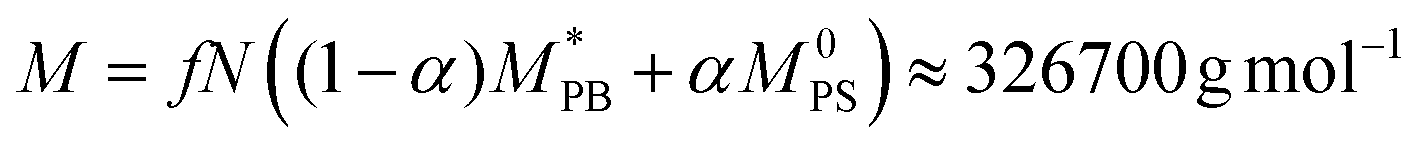
 , M0PB = 105 g mol−1 and M0PS = 720 g mol−1.27 In this estimate, we employ
  rather than M0PB as polybutadine and polysterene monomers have, in reality, different sizes (σPS = 2σPB). In our computational model, we do not account for this difference; thus we need to compute the mass accordingly (as each A-type monomer contains, effectively, twice the amount of material).
2.2. Simulation details
We simulate a single DCS brush in the bulk and under lateral confinement; the brush is always in contact with an implicit homogeneous fluid at temperature T. We perform Langevin Dynamics simulations using the molecular dynamics code LAMMPS,36 in which we implemented the B–B interaction. We set σ and kBT as the units of length and energy, respectively, and we choose the monomer mass m as the unit of mass; the colloid mass is mC = 1000m. Further, we fix the friction coefficient of the implicit fluid to γ = 1 and the elementary time step to Δt = 0.001 (in Lennard–Jones implicit units). The equations of motion are solved using a velocity-Verlet algorithm. We investigate DCS brushes characterized by α = 0.2, 0.3 and 0.4, 0.5 < λ < 1.2 in the bulk and 0.5 < λ < 1.15 under confinement, i.e., we range from weak to strong solvophobic conditions.In order to confine DCS brushes adiabatically/reversibly, we start from equilibrated bulk configurations, at fixed α and λ (as the ones showcased in Fig. 1), placed in the centre of the simulation box. We slowly bring the confining planes from the initial positions at the edges of the simulation box (i.e., L = 248σ) to a separation distance of L = 10.0σ in 1010 time-steps. Afterwards, we perform a further equilibration run of 109 time-steps. We consider different confinement regimes, from L = 9.4σ (strong confinement) to L = 32.0σ (bulk conditions). To achieve the strongest confinement considered, the confining planes are further moved from L = 10.0σ to L = 9.6σ in three steps, each consisting of 108 time-steps followed by additional 109 time-steps to ensure equilibration. For any separation larger than L = 10.0σ, we slowly draw the confining planes apart in 12 steps, as before consisting of 108 time-steps followed by additional 109 time-steps. The described compression/expansion protocol guarantees that the observed structures are equilibrium structures; we note that, as long as λ ≲ 1.1, even an abrupt compression/expansion of the brush would lead, after some additional time, to an equilibrium structure where the arms are free to migrate from patch to patch. Instead, beyond λ ≅ 1.1 (the exact value depending on α), the patches tend to crystallise and the typical time scale associated with arm migration becomes extremely long, longer than the simulation time; this happens also in the bulk. In such cases, non-equilibrium effects are bound to happen for any reasonable time interval between compression steps and the system will display non-equilibrium properties. Given this phenomenology, we restrict ourselves to λ ≤ 1.15. All the results presented in section 4 have been averaged, for each value of λ, α and L, over roughly 7000 independent patch realisations.
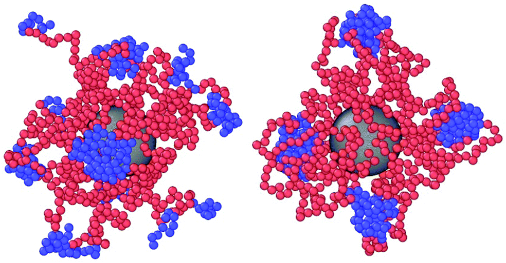 | ||
| Fig. 1 Snapshots of equilibrated DCS brushes in the bulk at infinite dilution. Left: α = 0.3 and λ = 0.5; right: α = 0.3 and λ = 1.2. | ||
2.3. Metric and patch properties
In this section, we present how patches are defined in this system and we detail how we characterise their properties and their spatial organization. Further, we introduce the metric properties, i.e., the size and shape of a molecule, that will be employed in order to describe the conformations of the DCS brushes in the bulk and under confinement.We are interested in the organization of the solvophobic sections of the arms; as seen in similar systems,23 these sections tend to form aggregates. Following Capone et al.,23 we name patch an aggregate of at least two monomers that experience a net attraction towards each other and belong to different arms. We quantify, in the bulk, under confinement and for each value of (λ, α) considered, the average number 〈NP〉 of such aggregates. We further compute the patch population, 〈SP〉, i.e., the average number of arms per patch and we characterise the relative position of the patches with respect to each other by computing the angle between each patch ΘP, defined as
cos (ΘP) = ![[v with combining circumflex]](https://www.rsc.org/images/entities/b_char_0076_0302.gif) i·j i·j | (4) |
i and j are unit vectors along the directions connecting the center of mass of the brush with the centers of mass of the i-th and j-th patch, respectively. We note that in the calculation of the average angle between the patches, 〈ΘP〉, we have the choice of considering either the angles of a patch with all the other ones or just with its nearest neighbors.
The size and shape of the whole DCS brush can be described by means of the eigenvalues and eigenvectors of the gyration tensor
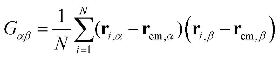 | (5) |
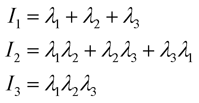
 and α and β stand for the three Cartesian coordinates. Specifically, given the three eigenvalues λ1, λ2 and λ3, with λ1 ≥ λ2 ≥ λ3, the average size of a DCS star can be estimated by computing the gyration radius Rg as the square root of the expectation value of the sum of the three eigenvalues, viz.:
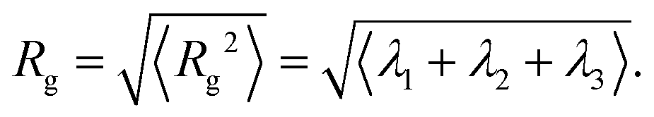 | (6) |
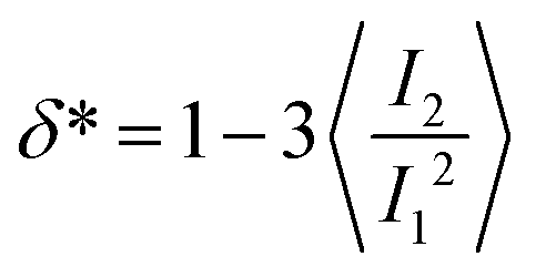
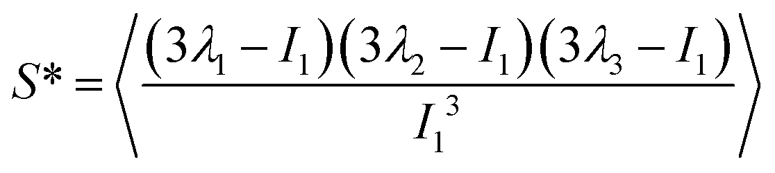
The value of the quantity Rg is of course dependent not only on molecular characteristics f, α and λ but also on the distance L between the confining walls. We do not explicitly denote all these dependencies in what follows for reasons of parsimony in notation; nevertheless we employ the notation R0g to signify the gyration radius in the bulk, i.e., in the absence of the confining walls. Under confinement, we also compute the relative shape anisotropy δ* and the prolateness S*![[thin space (1/6-em)]](https://www.rsc.org/images/entities/char_2009.gif) 30 as
30 as
 | (7) |
 | (8) |
 | (9) |
The prolateness is zero for spherical objects, assumes negative values for oblate (disk-like) shapes and positive values for prolate shapes. The shape anisotropy vanishes for high symmetric configurations and is positive otherwise.
3. Microelasticity model
Soft, deformable colloids such as the brushes at hand are characterized by steric effective interactions that are usually hard to quantify in terms of pairwise additive interactions, in particular for strong deformations and/or high polymer concentrations. To overcome this difficulty, we employ a theoretical model known as the Liquid Drop Model (LDM) in order to provide an effective description of the stars as an elastic medium, allowing us to treat steric interactions beyond pair additivity. In the LDM framework, the DCS brush is viewed as a liquid drop of volume V and surface area A, characterised by a free energy29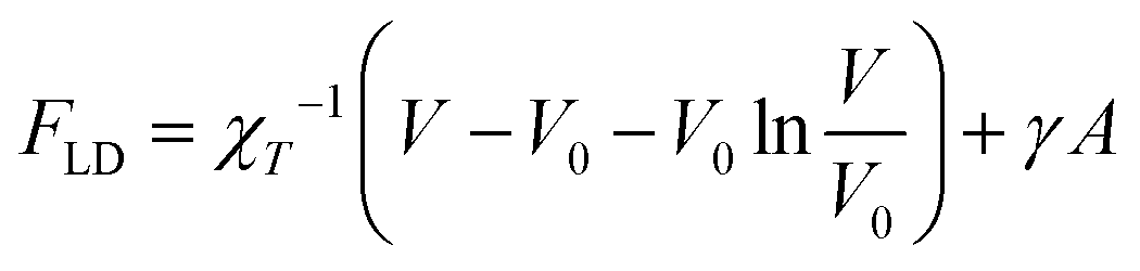 | (10) |
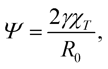
As detailed in ref. 29, γ is the surface tension of the droplet, V0 is a reference volume, chosen such that the pressure inside the drop – given by the Murnaghan equation of state31 – vanishes in absence of surface tension. Thus χT is the isothermal compressibility at vanishing pressure and surface tension. Within this framework, the deformation of a droplet is controlled by a single parameter, the reduced Egelstaff–Widom length Ψ
 | (11) |
For each degree of confinement, we calculate the deformation of the brush by modeling it as a liquid drop described by a parameter Ψ and minimizing the free energy in eqn (10) using the computer program Surface Evolver.32 The latter numerically minimizes the energy of a surface subject to constrains such as diametrical confinement. The minimization of the energy is accomplished by the gradient descent method, a standard first-order iterative optimization algorithm for finding a local minimum of a sufficiently regular function.
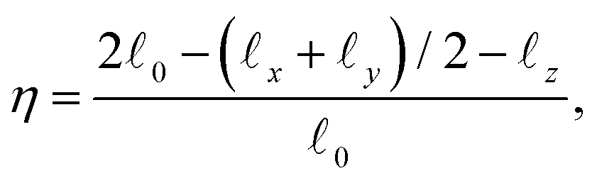
To determine the value of Ψ that best describes the brush, we calculate from the simulations the shape deformation of a single DCS and compare it with the theoretically predicted ones, selecting the Ψ-value that best fits the simulation data. The deformation of the brush under confinement is well-described by the quantity
 | (12) |
![[small script l]](https://www.rsc.org/images/entities/i_char_e146.gif) μ, μ = 0, x, y, z, are defined as appropriate moments over the monomer densities as follows.29 Let c0(r) be the spherically-averaged monomer density around the brush center and
μ, μ = 0, x, y, z, are defined as appropriate moments over the monomer densities as follows.29 Let c0(r) be the spherically-averaged monomer density around the brush center and 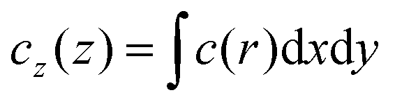 the projection of the same on the z-axis – the quantities cx(x) and cy(y) being defined in analogous ways by cyclic permutations of the x, y, z-indices. Then
  while lx, ly and lz are the half-thickness of the DCS in the x, y and z directions, respectively, defined as
  and analogously for x, y with z → x and x → y. We note that in ref. 29, an alternative measure for the shape deformation, ζ, was introduced. Here we choose η for numerical reasons, as ζ becomes very noisy for small deformations and hence, in that region, the numerical error can be large. Here, on the other hand, η → 0 in the bulk limit (no confinement), in which x,y,z → 0.
4. Results
4.1. DCS brushes in the bulk
In this section we present the results for DCS brushes in bulk conditions, reporting in particular on the gyration radius R0g, the average number of patches 〈NP〉 and the patch population 〈SP〉, as defined in section 2.3; all three quantities are reported in Fig. 2 for α = 0.2, 0.3, 0.4 as a function of λ. | ||
| Fig. 2 Metric and patch properties in the bulk: (A) average gyration radius R0g; (B) average number of patches 〈NP〉; (C) average patch population 〈SP〉. | ||
The size R0g decreases monotonically upon increasing λ (see Fig. 2A). The shrinking of the DCS brush is more pronounced as α increases: for α = 0.2, the value of R0g at the highest λ is around 3% smaller than its value at the lowest λ, while it decreases by ≈13% for α = 0.3, 0.4. The described shrinking can be linked to the patch formation. Indeed, note that the number of patches 〈NP〉 as function of λ has a non-monotonic behavior (see Fig. 2B): 〈NP〉 is already bigger than one at the lowest value of λ considered, and it reaches a maximum which, upon increasing α, shifts to lower values of λ. This behavior is associated with the initial aggregation of free arms into small patches and the subsequent merging of those into fewer and bigger ones, as λ grows. On the other hand, the patch population (reported in Fig. 2C) monotonically increases with λ from 〈SP〉 ≃ 2 up to a maximum of ten. We point out that the average patch population can assume values slightly smaller than two because, at low λ and α, patches are small and short-lived; configurations without patches may thus be sampled and included in the average process. We also notice that, even though the increase of 〈SP〉 is present for all α-values, it is more pronounced for α = 0.3, 0.4.
We can thus draw the following self-assembly picture at fixed α. First, at small λ-values, most of the DCS arms are not participating to aggregates: the product 〈SP〉〈NP〉 – that corresponds to the total number of arms recruited into patches – is much smaller than f. The few patches emerging at these λ-values are formed by a small number of arms. Increasing λ, both the number and the size of the patches increase: when 〈Np〉 reaches its maximum, 〈SP〉 is still relatively small, i.e., 2 < 〈SP〉 < 3, meaning that many loose arms are still present. Upon further increasing λ, the number of patches drops, while the patch population rapidly increases: more definite patches are formed in this regime, although a few loose arms are present in most cases. Indeed, at high values of λ the enthalpic gain due to the interactions between solvophobic monomers becomes large enough to overcome the entropic penalty due to the steric hindrance of the solvophilic part of the arms. For α = 0.4, we also observe a regime, at λ > 1, where the number of patches is fixed 〈Np〉 = 3 and the patch population is 〈Sp〉 ≃ 10; typically, every arm is recruited into a patch.
4.2. DCS brushes under confinement
Given the results shown in section 4.1, we focus on α = 0.3, 0.4 and we study the properties of DCS brushes under confinement (see Fig. 3). Note that we consider wall separations as low as L = 9.4σ, which corresponds to, roughly, a degree of confinement L/(2R0g) ≈ 0.5, the exact value depending on R0g at a given λ and α. We remark that, physically, the minimum possible distance between the confining planes is L = 8σ, corresponding to the size of the hard colloid at the center of the DCS brush. | ||
| Fig. 3 Snapshots of the DCS brushes under confinement at wall separation L = 10σ; first row: α = 0.4 and λ = 0.7 (A) top view and (B) side view. Second row: α = 0.4 and λ = 1.1 (C) top view and (D) side view. | ||
In Fig. 4 we report the prolateness S* and shape anisotropy δ* as function of the degree of confinement L/(2R0g) at fixed α = 0.3 and different values of λ. Qualitatively, the same results are observed for α = 0.4. As one might expect, the brushes tend to become oblate at small values of L/(2R0g); the prolateness does not change with λ, as it depends only on the geometry of the confinement (see panel A of Fig. 4). As the latter is released, the DCS brushes go back to their bulk shape: note that the shape retains some degree of anisotropy, which increases upon increasing λ (see panel B of Fig. 4), concurrently with the formation of larger patches in the bulk.
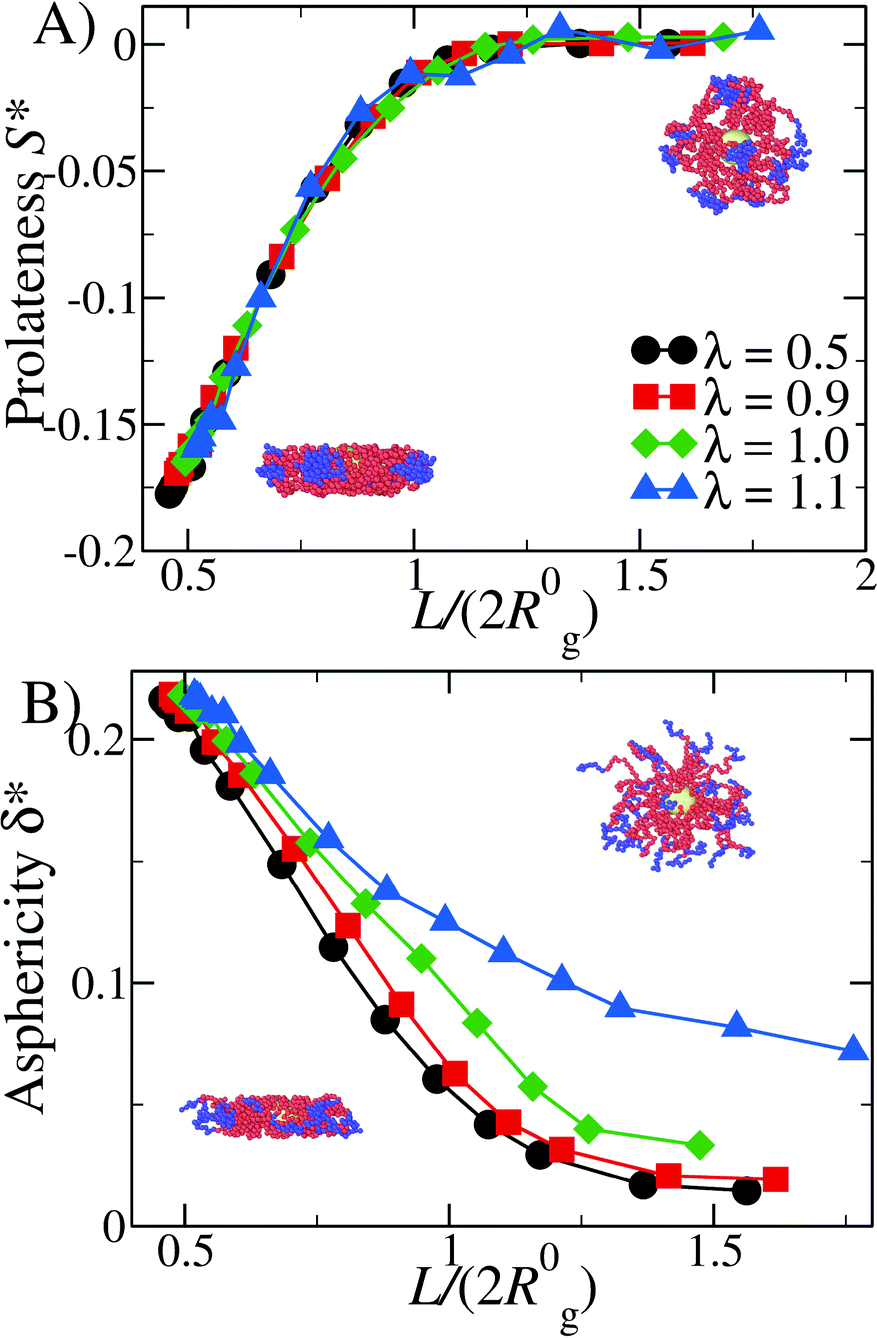 | ||
| Fig. 4 Metric properties under confinement: (A) prolateness S* and (B) shape anisotropy δ* as function of the degree of confinement L/(2R0g), for α = 0.3. Snapshots highlight the stark change in asphericity and prolateness; they refer to the system α = 0.3, in panel A λ = 1.0, L/(2R0g) = 0.51 (left), L/(2R0g) = 1.68 (right), in panel B λ = 0.5, L/(2R0g) = 0.47 (left), L/(2R0g) = 1.55 (right). | ||
We turn now our attention to the question of how the patchiness of our DCS brush is affected by the degree of confinement. To this aim, in Fig. 5 we report 〈NP〉, 〈SP〉, and the average total number of arms recruited into patches 〈NP〉〈SP〉 for both α = 0.3, 0.4 and 0.5 < λ < 1.15 as function of L/(2R0g). In Fig. 5 we can distinguish three different regimes in λ. For small values of λ (namely, λ < 0.8 for both α = 0.3 and 0.4), 〈NP〉 increases upon confinement, while 〈SP〉 remains low (order of two to four arms per patch). As showed in section 4.1, in this same range of λ-values, DCS brushes in the bulk assemble relatively few, small patches: upon increasing the confinement arms have a larger probability to interact with each other, although the magnitude of the interaction compared to the thermal energy remains small. Thus, the resulting patches are small but their number is higher than in the bulk; interestingly, the product 〈NP〉〈SP〉 increases on decreasing L/(2R0g), indicating that more and more arms are recruited into patches as we confine the system.
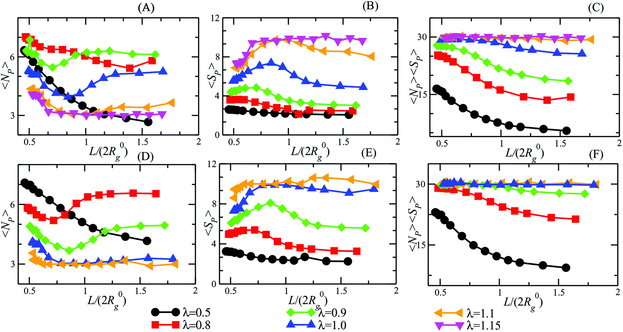 | ||
| Fig. 5 Patch properties under confinement, as a function of the degree of confinement L/(2R0g). Upper row (A)–(C): α = 0.3; lower row (D)–(F) α = 0.4. (A) and (D): Average number of patches 〈NP〉; (B) and (E): average patch population 〈SP〉; (C) and (F): average number of arms recruited into patches 〈Np〉〈Sp〉. | ||
Upon increasing λ (namely, 0.8 ≤ λ < 1.1 for α = 0.3 and 0.7 ≤ λ < 1.0 for α = 0.4), a non-monotonic behavior emerges in 〈NP〉 and 〈SP〉. Indeed, 〈NP〉 diminishes from the bulk value until it hits a minimum and then raises again at very high confinement; at the same time, 〈SP〉 raises until a maximum and then drops. Interestingly, the product 〈SP〉〈NP〉 remains monotonic as we increase the confinement, see Fig. 5(C) and (F), again signalling that more and more arms are recruited into patches.
Finally, at large λ-values (namely, λ ≥ 1.1 for α = 0.3 and λ ≥ 1.0 for α = 0.4), the observables remain essentially constant for a large range of confinement; only at very strong confinement (L/(2R0g) ≤ 0.7) 〈NP〉 grows while 〈SP〉 decreases. Notice that all arms are (on average) recruited into patches, as showed by 〈NP〉〈SP〉, regardless of the confinement. This happens because, at high λ values, big clusters are energetically favorite and only a great steric hindrance, such as the one caused by a strong confinement, can cause cluster breaking. In other words, for very strong confinement patches become too big to fit the available space and have to split. We note, additionally, that we have checked explicitly that the above-mentioned results represent a true equilibrium situation. Indeed, the patch characteristics have been checked to be identical independently of whether a particular degree of confinement is reached via compression from an extended brush or expansion of a more tightly confined one.
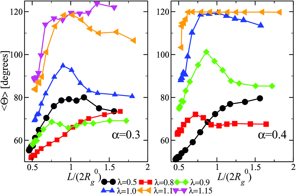
We now turn our attention to a crucially important quantity for the morphology and characterization of the soft patchy particles, namely the angle 〈ΘP〉 between the patches, taking neighboring ones as the most characteristic of the resulting arrangement; the results are shown in Fig. 6. We observe that, on changing λ and L/(2R0g), 〈ΘP〉 becomes compatible with the average angle of patches arranged on different regular polygons. In particular, if we focus on the regime of large λ-values and strong confinement, where almost all arms are recruited (see Fig. 5C and F, where 〈SP〉〈NP〉≃30), we observe the emergence of equilateral triangles, for which 〈Θ〉 = 120°, squares, 〈Θ〉 = 90°, and also other polygons, namely pentagons, 〈Θ〉 = 72°, and hexagons, 〈Θ〉 = 60°. Accordingly, a combination of confinement and temperature control, via the parameters L/(2R0g) and λ, allows us to transform these soft patchy particles into (soft) regular polygons with desired symmetry. The vertices of these polygons are the self-organized patches, and four characteristic snapshots of these soft patchy polygons are shown in Fig. 7. Confinement thus becomes key in producing self-organized and self-adjusting patchy polygons whose shape is adaptive to an externally controllable environment.
 | ||
| Fig. 6 The expectation value for the angle between vectors connecting the brush center to the centers of mass of neighboring patches, as a function of the degree of confinement, and for various values of α and λ, as indicated. | ||
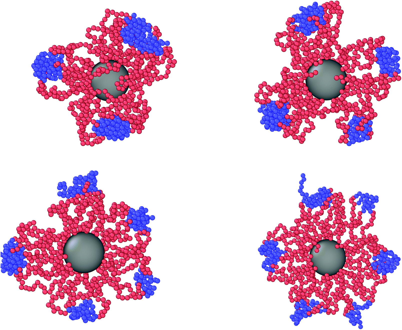 | ||
| Fig. 7 Simulation snapshots of stable, soft, patchy polygons formed by diblock copolymer star brushes under confinement, with the values of the corresponding confinement and physical parameters in parentheses. Clockwise from the top left corner: a triangle (α = 0.3, λ = 1.15, L/(2R0g) = 0.615); a square (α = 0.3, λ = 1.1, L/(2R0g) = 0.606); a hexagon (α = 0.3, λ = 0.9, L/(2R0g) = 0.485); and a pentagon (α = 0.3, λ = 1.0, L/(2R0g) = 0.547). | ||
4.3. DCS brushes in the liquid drop model framework
In this section, we carry on a comparison between numerical simulations and the theoretical model introduced in section 3. We compute the quantity η from numerical data, as described in section 2.3. From the perspective of the LDM, the DCS brush is described as a “hollow” droplet; once we minimize its surface energy with Surface Evolver, we can extract the longitudinal (x and y) and transverse (z) size from the largest values of the droplet surface along the x, y and z directions. The resulting theoretical η is naturally a function of the reduced degree of confinement L/D*, where D* is the diameter of the droplet. Note that, within the LDM, the unconfined droplet is, by definition, spherical and η = 0 as soon as we release the confinement, i.e., η = 0 for L/D* ≥ 1. On the other hand, simulated DCS brushes are not sharp objects and display the presence of a “corona”, i.e., a peripheral region extending over distances, measured from the center of mass, greater than the bulk gyration radius R0g. In order to obtain a meaningful comparison between numerical and theoretical results, we keep R0g as the characteristic length scale of the system, and we report all the data as function of L/2R0g, the degree of confinement. Given such a choice, we remark that the contribution of the corona to η will, in any case, not be captured by the LDM, as the corona is not present in the theoretical description. This is particularly important for large values of L/(2R0g). We effectively account for the corona by rescaling L/(2R0g) by an (arbitrary) factor κ, of order unity.
In Fig. 8 we report the comparison between numerical simulations and LDM data, plotting η as function of L/(2R0g) for different values of λ, at fixed α = 0.3 (Fig. 8A) and α = 0.4 (Fig. 8B). For both values of α, we report the values of the rescaling factor κ in Table 1.
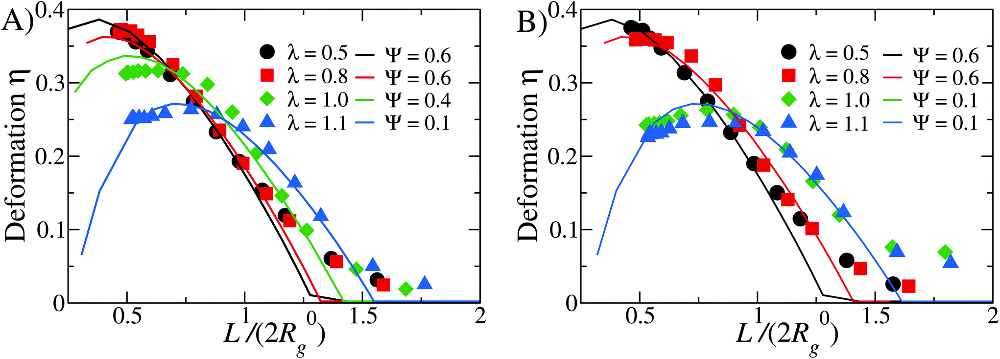 | ||
| Fig. 8 Comparison between simulations and theoretical data for different values of λ = as labeled: panel (A) α = 0.3 and panel (B) α = 0.4. Note that the theoretical curves have been rescaled on the x-axis by the factor κ, as reported in Table 1. | ||
| λ | α = 0.3 | α = 0.4 | ||
|---|---|---|---|---|
| Ψ | κ | Ψ | κ | |
| 0.5 | 0.6 | 1.30 | 0.6 | 1.30 |
| 0.8 | 0.6 | 1.30 | 0.6 | 1.41 |
| 1.0 | 0.4 | 1.45 | 0.1 | 1.61 |
| 1.1 | 0.1 | 1.60 | 0.1 | 1.61 |
We find that the numerical data are best fit by different values of the reduced Egelstaff–Widom length, in the range 0.1 ≤ Ψ ≤ 0.6. As λ is linked to the strength of the attraction between the solvophobic monomers, we expect γ to increase and χT to decrease as λ goes up. Since Ψ is proportional to both these quantities (see eqn (11)), the observed decrease of Ψ upon increasing λ seem to signal that χT is more sensible than γ to changes in λ. However, eqn (11) defines Ψ for a perfectly spherical droplet whose shape is fully captured by its radius R0. Since the DCS brushes become less and less spherical in the bulk as λ increases (see Fig. 4) there is also a geometrical prefactor that will, in general, depend on the λ-dependent DCS brush shape. This unknown prefactor makes it impossible to directly compare values of Ψ obtained for different λ-values.
At small λ-values (λ ≤ 0.8) the comparison between theory and simulations is excellent at small (L/(2R0g) ≤ 0.75) and intermediate (0.75 < L/(2R0g) ≤ 1.25) values of the degree of confinement: on the one hand, at these λ-values, the brush is compressible enough to be modeled as a liquid droplet even under strong confinement, on the other hand the “corona” contribution is substantial and leads to a notable discrepancy for L/(2R0g) > 1.25. In contrast, at high values of λ (e.g. λ ≥ 0.9), we notice that the numerical data are less well captured by the LDM at L/(2R0g) ≤ 0.75; however, at large degree of confinement the discrepancy is smaller with respect to the small λ case, and the intermediate regime is still very well captured by the LDM. We can rationalise these results as follows. At high λ-values, DCS brushes are characterised by big, compact patches: their “corona” is not very extended and its effect, for large degrees of confinement, is less relevant. Further, at small values of L/(2R0g), patches break down, as described in section 4.2; it is thus reasonable to assume that the re-grouping of the solvophobic monomers indeed has an effect on the elastic response of the brush, which is not fully captured by the LDM. Nevertheless, we remark that we obtain again a very good comparison at intermediate values of L/(2R0g) for all values of λ considered. Finally, the dependence of the Ψ-parameter on λ appears intuitive: for high λ-values, for which strong and compact patches form, Ψ decreases and the whole soft colloid appears thus to be less compressible. For small values of λ, on the other hand, we obtain Ψ ≅ 0.6, in agreement with previous results on self-avoiding, spherical homopolymer brushes.29
5. Conclusions
We have carried out a simulation study of model diblock copolymer spherical brushes with solvophobic ends under varying degrees of temperature quenching and geometric confinement, demonstrating thereby the ability to employ these systems as self-adjusting soft patchy nanoparticles for shape control. The resulting soft balls can be seen as elastic liquid drops as far as their overall deformation properties are concerned whilst, at the same time, they are ideal building blocks for the reversible fabrication of functional polygons in quasi two dimensions. Given the ability to synthesize such brushes through, e.g., the combination of polybutadine–polysterene block copolymers,27 experimental realization of such brushes should be within reach.Going to the next step in the hierarchical self-assembly scenario, the most promising avenue opened up from the shape control of these particles is that of stabilizing quasi-two-dimensional quasicrystals. One promising feature is the ability to create tunable triangular- and square-shaped particles, enabling thus the possibility of a square-triangle quasicrystalline tiling of the plane.33 Moreover, Reinhardt et al.34 have developed an approach to compute the free energy of quasicrystals, in order to calculate the phase diagrams of systems of two-dimensional hard patchy particles with five regularly arranged attractive patches. Pentavalent patchy particles have been shown there to assemble into a dodecagonal quasicrystal. They found that this quasicrystal has a thermodynamically stable phase for a wide range of conditions, e.g., a wide range of pressures, and remains robust as the potential parameters are varied. The (soft) pentagons discovered here might very well be the suitable building blocks for that purpose. Moreover, Dotera et al.35 proved that softness generically leads to the formation of quasicristalline order, further lending credibility to the perspective of two-dimensional soft matter quasicrystals.
Based on these previous results on two dimensional hard patchy colloids, as well as on the current findings, our next goal is to further investigate whether quasicrystals emerge by lowering the temperature in a quasi two dimensional system of DCS-brushes, as already observed for hard patchy colloids. Even at densities close to the overlap concentration, we expect the DCS brushes to maintain the conformational characteristics they feature at infinite dilution, since inter particle interactions start playing a role only at such conditions. Accordingly, it is pertinent to develop a coarse-grained description based on the salient features established at the single-particle level, thereby encompassing patch sizes and fluctuations, as well as angular distributions, through which it will be possible to simulate soft patchy colloids capable of self-assembling targeted structures. Work along these lines is currently underway.
Conflicts of interest
There are no conflicts to declare.Acknowledgements
We acknowledge many helpful discussions with Prof. Primož Ziherl (University of Ljubljana and Jožef Stefan Institute). IEVR acknowledges support from the Austrian Ministery of Science and the University of Ljubljana for its hospitality during a research visit. EB acknowledges support from the Austrian Science Fund (FWF) under Proj. No. Y-1163-N27. Computation time at the Vienna Scientific Cluster (VSC) is also gratefully acknowledged.References
- G. M. Whitesides and M. Boncheva, Science, 2002, 295, 2418 CrossRef CAS.
- S. C. Glotzer, Science, 2004, 306, 419 CrossRef CAS.
- L. Cademartiri and K. J. M. Bishop, Nat. Mater., 2015, 14, 2 CrossRef CAS.
- E. Bianchi, R. Blaak and C. N. Likos, Phys. Chem. Chem. Phys., 2011, 13, 6397 RSC.
- A. Pawar and I. Kretzschmar, Macromol. Rapid. Commun., 2010, 31, 150 CrossRef CAS.
- E. Bianchi, B. Capone, I. Coluzza, L. Rovigatti and P. D. J. van Oostrum, Phys. Chem. Chem. Phys., 2017, 19, 19847 RSC.
- F. Smallenburg and F. Sciortino, Nat. Phys., 2013, 9, 554–558 Search PubMed.
- F. Smallenburg, L. Filion and F. Sciortino, Nat. Phys., 2014, 653–657 Search PubMed.
- S. A. Mallory and A. Cacciuto, J. Am. Chem. Soc., 2019, 141, 2500–2507 CrossRef CAS.
- L. L. Treffenstädt, N. A. M. Araújo and D. de las Heras, Soft Matter, 2018, 14, 3572–3580 RSC.
- W. F. Reinhart and A. Z. Panagiotopoulos, J. Chem. Phys., 2019, 159, 014503 CrossRef.
- E. Locatelli and E. Bianchi, Soft Matter, 2019, 14, 8119 RSC.
- N. C. Seeman, J. Theor. Biol., 1982, 99, 237–247 CrossRef CAS.
- S. Biffi, R. Cerbino, F. Bomboi, E. M. Paraboschi, R. Asselta, F. Sciortino and T. Bellini, Proc. Natl. Acad. Sci. U. S. A., 2013, 110, 15633–15637 CrossRef CAS.
- M. Nakata, G. Zanchetta, B. D. Chapman, C. D. Jones, J. O. Cross, R. Pindak, T. Bellini and N. A. Clark, Science, 2007, 318, 1276 CrossRef CAS.
- E. Winfree, F. Liu, L. A. Wenzler and N. C. Seeman, Nature, 1998, 394, 539–544 CrossRef CAS.
- E. Locatelli, P. H. Handle, C. N. Likos, F. Sciortino and L. Rovigatti, ACS Nano, 2017, 11, 2094–2102 CrossRef CAS.
- L. Rovigatti, F. Smallenburg, F. Romano and F. Sciortino, ACS Nano, 2014, 8, 3567–3574 CrossRef CAS.
- I. C. Gârlea, E. Bianchi, B. Capone, L. Rovigatti and C. N. Likos, Curr. Opin. Colloid Interface Sci., 2017, 30, 1–7 CrossRef.
- N. A. Mahynski and A. Z. Panagiotopoulos, J. Chem. Phys., 2015, 142, 074901 CrossRef.
- P. Akcora, H. Liu, S. K. Kumar, J. Moll, Y. Li, B. C. Benicewicz, L. S. Schadler, D. Acehan, A. Z. Panagiotopoulos, V. Pryamitsyn, V. Ganesan, J. Ilavsky, P. Thiyagarajan, R. H. Colby and J. F. Douglas, Nat. Mater., 2009, 8, 354–359 CrossRef CAS.
- B. Bozorgui, D. Meng, S. K. Kumar and A. Cacciuto, Nano Lett., 2013, 13, 2732–2737 CrossRef CAS.
- B. Capone, I. Coluzza, F. Lo Verso, C. N. Likos and R. Blaak, Phys. Rev. Lett., 2012, 109, 238301 CrossRef.
- L. Rovigatti, B. Capone and C. N. Likos, Nanoscale, 2016, 8, 3288–3295 RSC.
- N. Qiu, Y. Li, Y. Li, H. Wang, Q. Duan and T. Kakuchi, RSC Adv., 2016, 6, 47912–47918 RSC.
- Y. Chuan, Q. L. Shao, V. Shrinivas, J. G. Shu, K. Xiyu, T. C. Xin, L. H. James and Y. Y. Yi, J. Controlled Release, 2015, 208, 93–105 CrossRef.
- E. Moghimi, I. Chubak, A. Statt, M. P. Howard, D. Founta, G. Polymeropoulos, K. Ntetsikas, N. Hadjichristidis, A. Z. Panagiotopoulos, C. N. Likos and D. Vlassopoulos, ACS Macro Lett., 2019, 8, 766–722 CrossRef CAS.
- E. Moghimi, I. Chubak, D. Founta, K. Ntetsikas, G. Polymeropoulos, N. Hadjichristidis, C. N. Likos and D. Vlassopoulos, Colloid Polym. Sci., 2020 DOI:10.1007/s00396-020-04742-0.
- J. Riest, L. Athanasopoulou, S. A. Egorov, C. N. Likos and P. Ziherl, Sci. Rep., 2015, 5, 15854 CrossRef.
- A. Narros, A. J. Moreno and C. N. Likos, Macromolecules, 2013, 46, 3654–3668 CrossRef CAS.
- F. D. Murnaghan, Proc. Natl. Acad. Sci. U. S. A., 1944, 30, 244–247 CrossRef CAS.
- K. A. Brakke, Exp. Math., 1992, 1, 141–165 CrossRef.
- C. N. Likos and C. L. Henley, Philos. Mag. B, 1993, 68, 85–113 CAS.
- A. Reinhardt, J. S. Schreck, F. Romano and J. P. K. Doye, J. Phys.: Condens. Matter, 2017, 29, 014006 CrossRef.
- T. Dotera, T. Oshiro and P. Ziherl, Nature, 2014, 506, 208–211 CrossRef CAS.
- S. Plimpton, J. Comp. Phys., 1995, 117, 1–19 CAS.
| This journal is © The Royal Society of Chemistry 2020 |