
 Open Access Article
 This Open Access Article is licensed under a
 Creative Commons Attribution 3.0 Unported Licence
Fine tuning of ferromagnet/antiferromagnet interface magnetic anisotropy for field-free switching of antiferromagnetic spins†
M.
Ślęzak
 *a,
P.
Dróżdż
a,
W.
Janus
a,
H.
Nayyef
a,
A.
Kozioł-Rachwał
a,
M.
Szpytma
a,
M.
Zając
b,
T. O.
Menteş
c,
F.
Genuzio
c,
A.
Locatelli
c and
T.
Ślęzak
a
*a,
P.
Dróżdż
a,
W.
Janus
a,
H.
Nayyef
a,
A.
Kozioł-Rachwał
a,
M.
Szpytma
a,
M.
Zając
b,
T. O.
Menteş
c,
F.
Genuzio
c,
A.
Locatelli
c and
T.
Ślęzak
a
aAGH University of Science and Technology, Faculty of Physics and Applied Computer Science, Kraków, Poland. E-mail: mislezak@agh.edu.pl
bNational Synchrotron Radiation Centre SOLARIS, Jagiellonian University, Kraków, Poland
cElettra – Sincrotrone Trieste, Basovizza, Trieste, Italy
First published on 28th August 2020
Abstract
We show that in a uniform thickness NiO(111)/Fe(110) epitaxial bilayer system, at given temperature near 300 K, two magnetic states with orthogonal spin orientations can be stabilized in antiferromagnetic NiO. Field-free, reversible switching between these two antiferromagnetic states is demonstrated. The observed phenomena arise from the unique combination of precisely tuned interface magnetic anisotropy, thermal hysteresis of spin reorientation transition and interfacial ferromagnet/antiferromagnet exchange coupling. The possibility of field-free switching between two magnetic states in an antiferromagnet is fundamentally interesting and can lead to new ideas in heat assisted magnetic recording technology.
Introduction
Magnetic anisotropy (MA), a relativistic manifestation of the coupling between the electron spin and the orbital moment, is a key parameter of magnetic materials. MA not only determines the preferential, spontaneous orientation of magnetic moments but it is also required for long range magnetic order in low dimensional systems, which makes it both fundamentally important and crucial for nanoscale applications.1,2 While engineering of MA in ferromagnets (FM) has been so far intensively studied, the control of antiferromagnets (AFM) is only nowadays in the focus of attention of the magnetism community. The aim of AFM spintronics is to complement or replace ferromagnets as the active components of spintronic devices.3,4 Four kinds of AFMs manipulation can be defined5 that rely on application of magnetic, strain, electrical or optical methods. Magnetic control includes either the application of a strong external magnetic field or, when antiferromagnet is exchange-coupled to a neighboring ferromagnet,6 its magnetic state can be controlled by relatively small external magnetic field.7Here we show that fine tuning the MA of the ferromagnetic sublayer in a FM/AFM bilayer leads to the generation of two orthogonal AFM spin states at given temperature near 300 K. In order to implement field-free switching between these two AFM spin states, we combine two distinct features, interfacial AFM–FM exchange interaction and temperature-induced spin reorientation transition (SRT) in FM layer. In epitaxial NiO(111)/Fe(110) bilayers, we take the advantage of the intrinsic hysteresis of the temperature induced SRT in Fe(110) layer and at given temperature we directly document the existence of two orthogonal magnetic states in the AFM NiO(111) sublayer.
Results and discussion
The model system used in this work is a NiO/Fe(110) bilayer epitaxially grown on a W(110) single crystal. In the Fe/W(110) system, the evolution of the intrinsic uniaxial magnetic anisotropy with the thickness of the Fe layer results in the well-known spin-reorientation-transition (SRT).8–10 This SRT causes the Fe magnetization to switch from the [1−10] to the [001] in-plane direction as the Fe thickness increases above a critical value of the order of 150 ± 100 Å, depending on preparation conditions or type of the overlayers used to cover Fe(110).11,12,20 Importantly, the SRT also occurs in NiO/Fe(110) bilayers and can be imaged using X-ray magnetic circular dichroism photo-emission electron microscopy (XMCD-PEEM),13 as seen in Fig. 1. A special sample was prepared for PEEM experiments, that consisted of adjacent 50 Å and 150 Å thick Fe(110) regions covered by homogenous 40 Å thick NiO(111) overlayer. In this sample, the SRT is found at the boundary separating the Fe regions exhibiting different thicknesses.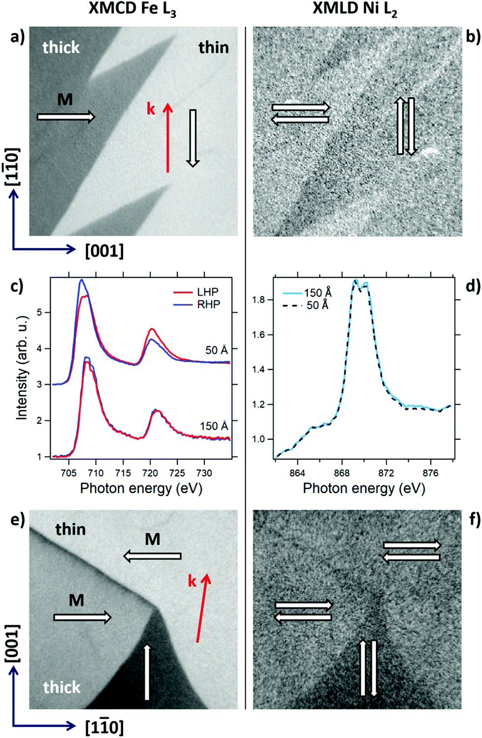 | ||
| Fig. 1 (a) Fe L3 XMCD-PEEM image of the SRT in NiO/Fe(110) at the 150 Å Fe (left)/50 Å Fe (right) boundary. The image contrast originates from the relative alignment of the photon helicity k and magnetization M. On the left hand side, M is oriented in-plane along [001], on the right along [1−10]; (b) corresponding Ni L2 XMLD-PEEM image of the same area shown in (a); (c) laterally-resolved XMCD spectra from the two regions quantitatively explain the contrast observed in (a). The spectra have been offset for clarity; (d) Ni L2 XMLD spectra acquired with polarization of the photon beam parallel to the sample plane from the thin and thick parts; (e and f) Fe L3 XMCD and Ni L2 XMLD images of a different region of the boundary after rotating the sample by ∼81°, respectively. In all images, the scale bar is 2 μm. White arrows on PEEM images indicate the local orientations of FM and AFM magnetic moments. For both PEEM measurements geometries, black arrows indicate crystallographic orientation of the sample with respect to the direction of the incoming photon beam k. | ||
In Fig. 1a, a room temperature (RT) XMCD-PEEM image of the Fe (50/150 Å) boundary is shown. The vertical direction coincides with the Fe[1−10] axis, which is parallel to the photon beam direction k. The characteristic zig-zag pattern14 of the magnetic domain structure clearly indicates that the 90°, sharp in-plane rotation of the magnetization occurs across the Fe(50 Å/150 Å) boundary. The image contrast observed in Fig. 1a can be quantitatively understood looking at the laterally-resolved XMCD spectra shown in Fig. 1c, which clearly demonstrate the large asymmetry observed in the region where M is oriented along [1−10] (right hand side of Fig. 1a); note also that there is no XMCD effect on the thick, part of the sample, where M is oriented along [001].
The domain structure of antiferromagnetic NiO was imaged using X-ray magnetic linear dichroism (XMLD)-PEEM at the Ni L2 edge (Fig. 1b), with the linear polarization of incoming X-rays oriented in the Fe(110)∥NiO(111) surface plane along the Fe[001]∥NiO[01−1] direction. There can be no doubt that the magnetic domain structure of Fe in the vicinity of SRT is directly imprinted into the antiferromagnetic NiO overlayer. The transition between orthogonally oriented ferromagnetic Fe regions is identically reflected in the shape of the magnetic domain structure of AFM NiO. XAS spectra extracted from sample regions before and after the SRT show small but noticeable XMLD effect in NiO at RT, as seen by comparing the height of the second XAS peak in the spectra extracted from the thin and thick parts of the sample. As expected for the uncompensated AFM/FM interface, NiO and Fe spins couple collinearly, which is confirmed by comparison of our XMLD results with analysis presented by Zhu et al.15 To the best of our knowledge, up to now ref. 15 is the only work reporting XMLD studies on (111) oriented NiO films. Summarizing, Fig. 1a–d show that SRT from the Fe[1−10] to the Fe[001] in Fe is accompanied by the SRT in the antiferromagnetic NiO, i.e. from the NiO[−211]∥Fe[1−10] to the NiO[01−1]∥Fe[001]. Please see ESI† for detailed analysis of structural properties of the studied NiO/Fe bilayers.
XMCD- and XMLD-PEEM images were also acquired after the in-plane rotation of the sample by ∼81°, so that the direction of incoming X-ray beam was slightly misaligned (by ∼9°) with respect to the Fe[001] in-plane direction, see Fig. 1e and f. Because of the small misalignment from the beam direction, on the 50 Å side of the boundary, the two antiparallel ferromagnetic domains (bright areas) oriented along Fe[1−10] can be discerned in the XMCD-PEEM image (Fig. 1e), where they appear with slightly different XMCD contrast. Conversely, a large XMCD effect is observed on the domains where M is oriented along [001], as confirmed by XMCD spectra (not shown) acquired with opposite helicities of incoming light (circular right and left polarizations). In Fig. 1e one can also notice a Néel domain wall that separates two [1−10] ferromagnetic domains and results in a magnetic contrast identical to that of the dark [001] domain. Again, the transition between orthogonally oriented ferromagnetic Fe regions is ideally reflected in the magnetic domain structure of AFM NiO (Fig. 1f). Note, however, that the magnetic contrast between the two antiparallel [1−10] Fe domains in Fig. 1e is not visible in the Ni L2 XMLD image, as expected for an antiferromagnetic overlayer. On the other hand, the [001] oriented Fe Néel domain wall in Fig. 1e is distinctively visible in the XMLD-PEEM image (Fig. 1f), with similar contrast as the large triangular [001]-oriented domain.
All in all, Fig. 1 proves that in-plane, 90-degree SRT is observed across the Fe(50 Å/150 Å) border in both FM Fe and AFM NiO sublayers in NiO(111)/Fe(110) stack. It is important to underline that the contrast visible in Fig. 1b and f images totally vanishes when the X-ray polarization is along the surface normal. This directly confirms that antiferromagnetic NiO spins rotate within the NiO(111) sample plane and no out-of-plane magnetic components are generated. Importantly, XMCD-PEEM images acquired at the Ni L3 edge do not show any magnetic contrast across the Fe(50 Å/150 Å) border, which confirms that the origin of the contrast observed in Fig. 1b and f is to be purely ascribed to magnetic linear dichroism.
The coupling with the underlying Fe layer leads to the idea of field-free switching of AFM NiO states in a NiO/Fe system with uniform thicknesses. In order to do this, one has to precisely tune the thickness of Fe sublayer to ensure that the effective in-plane magnetic anisotropy of Fe is almost zero and consequently the NiO/Fe bilayer is very close to the critical Fe SRT thickness. At room temperature (red arrows in Fig. 2a), the magnetization of Fe layer switches from [1−10] to [001] in-plane direction above dFe = 90 Å. At this critical SRT thickness, the Fe film has a very small MA, making it possible to induce a rotation of M towards [001] with temperature, which in ferromagnetic systems can originate from specific temperature dependence of MA constants.16 Indeed, at T = 80 K we clearly observe the shift of the SRT critical thickness towards lower dFe values as marked with blue color in Fig. 2a. This means that a temperature-induced, in-plane, [1−10] to [001] SRT takes place in the in Fe sublayer of the NiO(40 Å)/Fe(90 Å) bilayer. This result is deduced from XMCD and confirmed by MOKE hysteresis curves acquired with external magnetic field along in-plane [001] direction. A typical hard-axis magnetic hysteresis loop, characterized by the very small anisotropy field, is observed at T = 300 K, as shown by the red curve in Fig. 2b. At T = 80 K instead, the magnetic hysteresis loop of the NiO(40 Å)/Fe(90 Å) bilayer becomes easy-like and square-shaped proving that the temperature triggered SRT in the ferromagnetic layer is complete for this particular thickness of Fe.
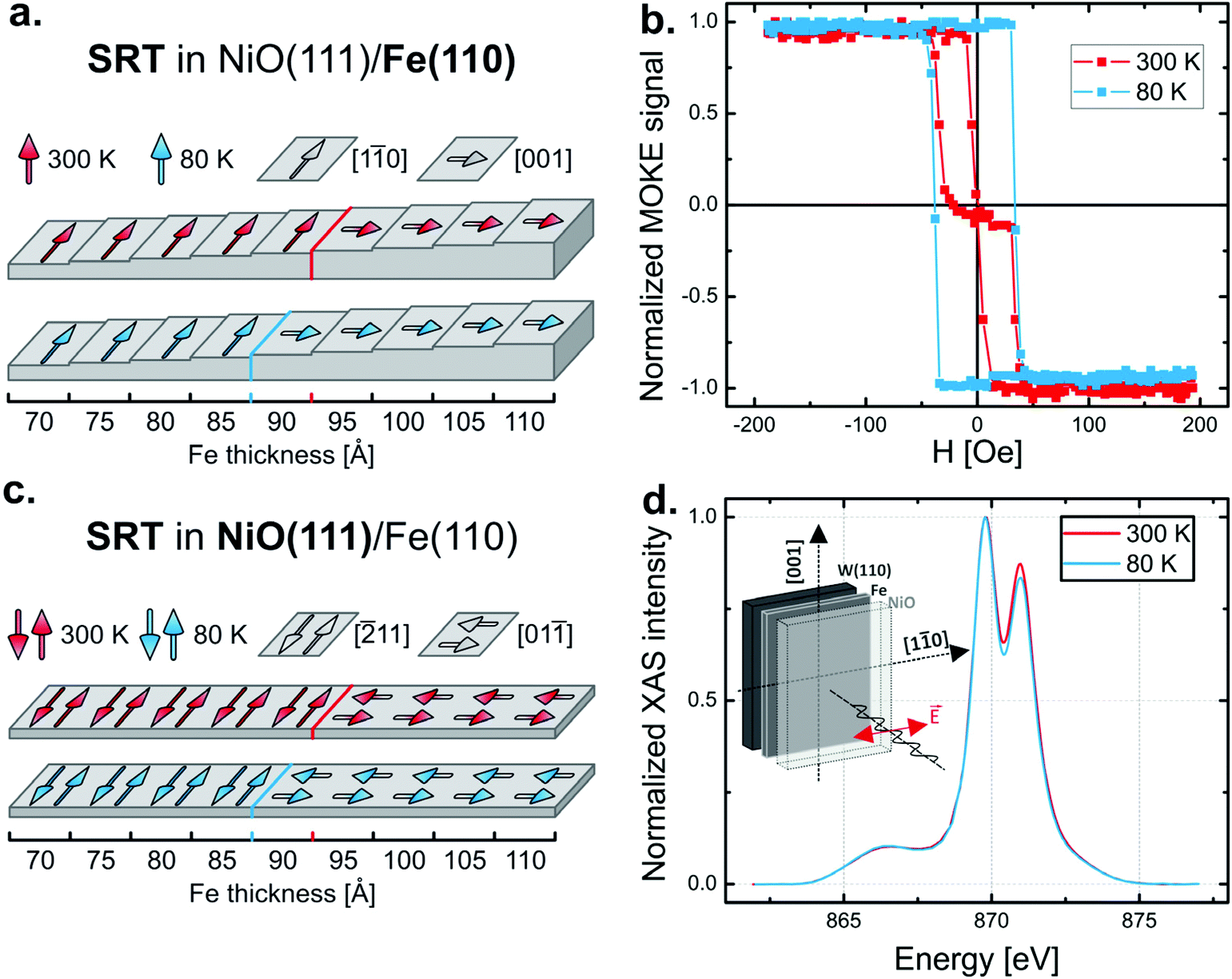 | ||
| Fig. 2 (a) At RT and 80 K, the dependence of Fe spin orientation on its thickness as concluded from XMCD and MOKE results. (b) Temperature induced SRT in 90 Å thick Fe sublayer documented by the change of magnetic hysteresis loops. (c) RT and 80 K dependence of AFM NiO spin orientation on the thickness of Fe sublayer as concluded from XMLD studies. The schematic geometry of the XMLD experiment and the exemplary XAS spectra acquired with linear polarization of the photon beam, at RT and 80 K are shown in (d) for dFe = 90 Å. | ||
Temperature dependent orientation of magnetic moments in antiferromagnetic NiO overlayer was addressed by performing XAS with linear polarization of incoming photon beam at the XAS end-station of National Synchrotron Radiation Centre Solaris in Kraków.21 As applied in the AFM-imaging experiment shown in Fig. 1, the magnitude of the XMLD effect in NiO is routinely defined by the so called RL2 ratio of the two peaks of the L2 edge.17 In our case it is convenient to define RL2 ratio as the higher-energy peak intensity divided by the intensity of the lower-energy peak. Systematic XMLD measurements performed as a function of temperature and NiO thickness (not shown) prove that the direction of NiO spins is totally determined by the orientation of Fe spins. This result means that at least three possible ways to rotate the antiferromagnetic NiO spins are available in NiO(111)/Fe(110) bilayers. Namely, one can change the orientation of Fe by changing: (i) thickness, (ii) temperature or (iii) by applying small external magnetic field. In each of these cases the spins of antiferromagnetic NiO rotate (together with Fe spins) by 90 degrees within the (111) plane. The thickness-induced scenario (i) has been already shown in Fig. 1. In the following we focus on the most interesting possibility (ii), as it can be realized in a uniform thickness system in a field-free and reversible manner. For dFe = 90 Å, a comparison of NiO XAS spectra (Fig. 2d) at T = 300 K and at T = 80 K indicates that temperature induced Fe[1−10] to Fe[001] SRT in Fe is accompanied by NiO[−211]∥Fe[1−10] to the NiO[01−1]∥Fe[001] SRT in antiferromagnetic NiO(111), as schematically shown in Fig. 2c.
We underline that the idea of the present experiment goes beyond such a simple temperature induced excitation of SRT in both coupled Fe and NiO sublayers. The goal of our experiment was to make use of theoretically predicted,18 although rarely reported,19 thermal-hysteresis of SRT in the ferromagnetic system, which signifies that two orthogonal ferromagnetic states can be stabilized at the same temperature depending on the pathway taken to reach that temperature. Consequently, temperature induced SRT in ferromagnetic Fe, together with its hysteresis and AFM–FM exchange coupling should serve as a tool to stabilize, at a given temperature, either of the two orthogonal magnetic states of the antiferromagnetic NiO overlayer. These AFM states can further be reversibly switched by temperature change only.
To test this possibility we performed systematic temperature dependent XAS measurements of NiO(111)/Fe(110) bilayers, for Fe thicknesses close to dFe = 90 Å. In Fig. 3 we present the temperature dependence of normalized XMCD signal and the raw XMLD data (as defined by the RL2 ratio). For dFe = 85 Å, the Fe magnetization is oriented along in-plane [1−10] within whole studied temperature range, as confirmed by the temperature dependence of XMCD results shown in the upper panel of Fig. 3 (triangles). With decreasing temperature the [001] in-plane MA of Fe(110) should increase16 but this change is too small to induce the rotation of the 85 Å thick Fe sublayer magnetization. On the other hand, 95 Å thick Fe film is temperature independently magnetized along in-plane [001] direction (squares in the upper panel of Fig. 3), as with the decreasing temperature its [001] MA becomes even stronger. Due to FM–AFM coupling, in both dFe = 85 Å and dFe = 95 Å cases the orientation of NiO magnetic moments (traced by the value of RL2 ratio which is presented in the lower panel of Fig. 3) is consequently fixed along NiO[−211]∥Fe[1−10] and NiO[01−1]∥Fe[001] directions, respectively. Instead, in the case of dFe = 90 Å, Fe sublayer undergoes a temperature driven in-plane SRT from [1−10], at high, to [001] at low temperature, as confirmed by the XMCD data in Fig. 3.
 | ||
| Fig. 3 Temperature dependence of XMCD and XMLD (defined by the RL2 ratio, see text for details) in NiO(111)/Fe(110) bilayer. Three Fe thicknesses are here analyzed, dFe = 85, 90 and 95 Å. In the most interesting dFe = 90 Å case, a field-free switching of AFM NiO spins is demonstrated. In 230–270 K temperature range, for each given temperature there are two local minima of energy and consequently NiO(40 Å)/Fe(90 Å) system can switch from (FM[1−10], AFM[−211]) magnetic state stabilized during cooling procedure to the (FM[001], AFM[01−1]) state which is stable on the heating branch up to ∼270 K. | ||
We observe a large thermal hysteresis of this temperature induced SRT spanning from 230 K to 270 K. Therefore, for each given temperature within this range, there are two possible equilibrium states characterized by the orthogonal orientations of Fe magnetization. Because of the FM–AFM coupling between Fe and NiO sublayers, two orthogonal magnetic states are also observed in antiferromagnetic NiO sublayer, as clearly confirmed by temperature dependence of the RL2 ratio marked by circles in the lower panel of Fig. 3. On the cooling branch, within temperature hysteresis the (FM[1−10], AFM[−211]) magnetic state is stable while on the heating branch the system persists in the orthogonal (FM[001], AFM[01−1]) state. Repeatable switching between these two orthogonal states can be realized by subsequent cycles of short, temporal heating and cooling the sample above 270 K and below 230 K, respectively.
Conclusions
In conclusion, we show that fine tuning of the well-defined uniaxial magnetic anisotropy of the ferromagnet leads to either of the two orthogonal magnetic states in the adjacent exchange-coupled antiferromagnet. The reported phenomena requires fine tuning of the interfacial magnetic anisotropy at the level of μeV per atom which corresponds to the ferromagnet thickness control in the sub-nano range, i.e. with the monolayer (∼2%) accuracy. Such interface engineering has to be additionally combined with the thermal-hysteresis of spin reorientation process which is necessary to induce two possible magnetic states of the system at given temperature. Fundamentally interesting and important for applications such as heat assisted magnetic recording is the possibility of field-free switching between two magnetic states in an antiferromagnet.Conflicts of interest
There are no conflicts to declare.Acknowledgements
This work is part of the scientific activities of the CERIC-ERIC internal project MAG-ALCHEMI. A. K.-R. was supported by the “Antiferromagnetic proximity effect and development of epitaxial bimetallic antiferromagnets – two routes towards next-generation spintronics” project which is carried out within the Homing programme of the Foundation for Polish Science co-financed by the European Union under the European Regional Development Fund.References
- C. A. F. Vaz, J. A. C. Bland and G. Lauhoff, Rep. Prog. Phys., 2008, 71, 056501 CrossRef.
- P. J. Jensen and K. H. Bennemann, Surf. Sci. Rep., 2006, 61, 129–199 CrossRef CAS.
- D. Kriegner, K. Vyborny, K. Olejnik, H. Reichlova, V. Novak, X. Marti, J. Gazquez, V. Saidl, P. Nemec, V. V. Volobuev, G. Springholz, V. Holy and T. Jungwirth, Nat. Commun., 2016, 7, 11623 CrossRef CAS PubMed.
- B. G. Park, J. Wunderlich, X. Martí, V. Holý, Y. Kurosaki, M. Yamada, H. Yamamoto, A. Nishide, J. Hayakawa, H. Takahashi, A. B. Shick and T. Jungwirth, Nat. Mater., 2011, 10, 347–351 CrossRef CAS PubMed.
- C. Song, Y. You, X. Chen, X. Zhou, Y. Wang and F. Pan, Nanotechnology, 2018, 29, 112001 CrossRef PubMed.
- J. Wu, D. Carlton, J. S. Park, Y. Meng, E. Arenholz, A. Doran, A. T. Young, A. Scholl, C. Hwang, H. W. Zhao, J. Bokor and Z. Q. Qiu, Nat. Phys., 2011, 7, 303–306 Search PubMed.
- J. Wu, J. S. Park, W. Kim, E. Arenholz, M. Liberati, A. Scholl, Y. Z. Wu, C. Hwang and Z. Q. Qiu, Phys. Rev. Lett., 2010, 104, 217204 CrossRef CAS PubMed.
- U. Gradmann, J. Korecki and G. Waller, Appl. Phys. A, 1986, 39, 101 CrossRef.
- T. Ślȩzak, M. Ślȩzak, M. Zaj
![[a with combining cedilla]](https://www.rsc.org/images/entities/char_0061_0327.gif) c, K. Freindl, A. Kozioł-Rachwał, K. Matlak, N. Spiridis, D. Wilgocka-Ślȩzak, E. Partyka-Jankowska, M. Rennhofer, A. I. Chumakov, S. Stankov, R. Rüffer and J. Korecki, Phys. Rev. Lett., 2010, 105, 027206 CrossRef PubMed.
c, K. Freindl, A. Kozioł-Rachwał, K. Matlak, N. Spiridis, D. Wilgocka-Ślȩzak, E. Partyka-Jankowska, M. Rennhofer, A. I. Chumakov, S. Stankov, R. Rüffer and J. Korecki, Phys. Rev. Lett., 2010, 105, 027206 CrossRef PubMed. - T. Ślȩzak, M. Zajc, M. Ślȩzak, K. Matlak, A. Kozioł-Rachwał, D. Wilgocka-Ślȩzak, A. I. Chumakov, R. Rüffer and J. Korecki, Phys. Rev. B: Condens. Matter Mater. Phys., 2013, 87, 094423 CrossRef.
- M. Ślęzak, T. Ślęzak, K. Matlak, B. Matlak, P. Dróżdż, T. Giela, D. Wilgocka-Ślęzak, N. Pilet, J. Raabe, A. Kozioł-Rachwał and J. Korecki, Phys. Rev. B: Condens. Matter Mater. Phys., 2016, 94, 014402 CrossRef.
- M. Ślęzak, T. Ślęzak, P. Dróżdż, B. Matlak, K. Matlak, A. Kozioł-Rachwał, M. Zając and J. Korecki, Sci. Rep., 2019, 9, 889 CrossRef PubMed.
- T. O. Menteş, G. Zamborlini, A. Sala and A. Locatelli, Beilstein J. Nanotechnol., 2014, 5, 1873–1886 CrossRef PubMed.
- E. Vescovo, T. O. Menteş, J. T. Sadowski, J. M. Ablett, M. A. Niño and A. Locatelli, Phys. Rev. B: Condens. Matter Mater. Phys., 2010, 82, 184405 CrossRef.
- W. Zhu, L. Seve, R. Sears, B. Sinkovic and S. S. P. Parkin, Phys. Rev. Lett., 2001, 86, 5389 CrossRef CAS PubMed.
- F. Gerhardter, Y. Li and K. Baberschke, Phys. Rev. B: Condens. Matter Mater. Phys., 1993, 47, 11204 CrossRef CAS PubMed.
- Y. Z. Wu, Z. Q. Qiu, Y. Zhao, A. T. Young, E. Arenholz and B. Sinkovic, Phys. Rev. B: Condens. Matter Mater. Phys., 2006, 74, 212402 CrossRef.
- Y. Millev and J. Kirschner, Phys. Rev. B: Condens. Matter Mater. Phys., 1996, 54, 4137–4145 CrossRef CAS PubMed.
- C. S. Arnold and D. P. Pappas, Phys. Rev. Lett., 1999, 83, 3305–3308 CrossRef CAS.
- M. Ślęzak, P. Dróżdż, K. Matlak, A. Kozioł-Rachwał, J. Korecki and T. Ślęzak, J. Magn. Magn. Mater., 2020, 497, 165963 CrossRef.
- M. Zając, T. Giela, K. Freindl, J. Korecki, E. Madej, M. Sikora, N. Spiridis, M. Stankiewicz, J. Stępień, J. Szade, M. Ślęzak, T. Ślęzak and D. Wilgocka-Ślęzak, Synchrotron Radiat. Nat. Sci., 2020, 19, 1 Search PubMed.
Footnote |
| † Electronic supplementary information (ESI) available. See DOI: 10.1039/d0nr04193a |
| This journal is © The Royal Society of Chemistry 2020 |