
Key issues facing electrospun carbon nanofibers in energy applications: on-going approaches and challenges†
Guangdi
Nie
 ab,
Xinwei
Zhao
a,
Yaxue
Luan
a,
Jiangmin
Jiang
b,
Zongkui
Kou
*b and
John
Wang
*b
ab,
Xinwei
Zhao
a,
Yaxue
Luan
a,
Jiangmin
Jiang
b,
Zongkui
Kou
*b and
John
Wang
*b
aIndustrial Research Institute of Nonwovens & Technical Textiles, College of Textiles and Clothing, Qingdao University, Qingdao, 266071, P. R. China
bDepartment of Materials Science and Engineering, National University of Singapore, Singapore 117574. E-mail: msekz@nus.edu.sg; msewangj@nus.edu.sg
First published on 26th May 2020
Abstract
Electrospun carbon nanofibers (CNFs), with one-dimensional (1D) morphology, tunable size, mechanical flexibility, and functionalities by themselves and those that can be added onto them, have witnessed the intensive development and extensive applications in energy storage and conversion, such as supercapacitors, batteries, and fuel cells. However, conventional solid CNFs often suffer from a rather poor electrical conductivity and low specific surface area, compared with the graphene and carbon nanotube counterparts. A well-engineered porous structure in CNFs increases their surface areas and reactivity, but there is a delicate balance between the level and type of pores and mechanical robustness. In addition, CNFs by themselves often show unsatisfactory electrochemical performance in energy storage and conversion, where, to endow them with high and durable activity, one effective approach is to dope CNFs with certain heteroatoms. Up to now, various activation strategies have been proposed and some of them have demonstrated great success in addressing these key issues. In this review, we focus on the recent advances in the issue-oriented schemes for activating the electrospun CNFs in terms of enhancing the conductivity, modulating pore configuration, doping with heteroatoms, and reinforcing mechanical strength, in close reference to their applications in supercapacitors. The basic scientific principles involved in these activation processes and their effectiveness in boosting the electrochemical performance of CNFs are examined. Finally, some of the on-going challenges and future perspectives in engineering CNFs for better performance are highlighted.
 Guangdi Nie | Guangdi Nie obtained her bachelor's degree (2012) and Ph.D. (2017) in Polymer Chemistry and Physics from the College of Chemistry, Jilin University under the supervision of Prof. Ce Wang. She then joined Qingdao University in 2017 as an Associate Professor. During 2019–2020, she worked with Prof. John Wang as a visiting scholar at the Department of Materials Science and Engineering, National University of Singapore. Her current research is focused on the electrospun nanomaterials for applications in electrocatalysis and energy storage devices. |
 Jiangmin Jiang | Jiangmin Jiang received his master's degree in Applied Chemistry, from Nanjing University of Aeronautics and Astronautics in 2017. He is now a joint Ph.D. student under the supervision of Prof. John Wang at the National University of Singapore and Prof. Xiaogang Zhang at Nanjing University of Aeronautics and Astronautics. His current research mainly focuses on the advanced materials for electrochemical energy storage devices. |
 Zongkui Kou | Zongkui Kou is currently a Research Fellow in Prof. John Wang's research group at the Department of Materials Science and Engineering, National University of Singapore. He received his Ph.D. degree (2017) from Wuhan University of Technology in Prof. Shichun Mu's group. He has published more than 30 first-author/corresponding-author papers in top international refereed journals, including Advanced Energy Materials, Advanced Functional Materials, ACS Energy Letters, Nano Energy, ACS Catalysis, etc. Currently, his research interests cover the functionalization and understanding of electrocatalysts and electrode materials for application in clean energy-related devices, including water splitting, nitrogen reduction reaction, metal-air/metal-ion batteries and supercapacitors. |
 John Wang | John Wang is a Professor at the Department of Materials Science and Engineering, National University of Singapore, and an Academician of the Asia Pacific Academy of Materials (APAM). He has more than 30 years of experience in the research and education of functional materials and materials chemistry. His current research interest covers energy materials and devices, 2D materials chemistry, and nanostructured materials for energy and water technologies. |
1. Introduction
Carbon materials, as a class of the most versatile materials on Earth with a huge family, including activated carbon (AC), graphene, carbon nanotubes (CNTs), carbon nanofibers (CNFs), mesoporous carbon, etc., have been involved in various energy applications, such as supercapacitors, metal-ion/air batteries, fuel cells, and CO2 reduction reaction, owing to their diverse micro-/nano-structures (e.g., particle, sphere, fiber, tube, sheet, and porous configuration), relatively good electronic/electrical conductivity, rich surface chemistry, excellent chemical/thermal/mechanical stability, abundant resources, low cost, and excellent environmental compatibility.1–3 Among these carbonaceous materials, CNFs with a one-dimensional (1D) nature, which are characterized by tunable architectures, a large length to diameter ratio (LDR), efficient electron/charge transfer along the longitudinal direction, robust mechanical flexibility, and easy assembly into wearable devices, have attracted extensive attention over the past decade.4 At present, there are a variety of strategies to prepare CNFs, e.g., electrospinning, chemical vapor deposition (CVD), self-assembly, template-directed synthesis, and hydrothermal conversion,4–7 where electrospinning is considered as the most facile and highly controllable approach to fabricate CNFs with designed architectures and freestanding functionality.8–10 Specifically, CNFs are often produced by the thermal treatment of electrospun polymer nanofibers (Fig. 1A), including those made of polyacrylonitrile (PAN), polyvinylpyrrolidone (PVP), cellulose acetate (CA), polyvinyl alcohol (PVA), polymethyl methacrylate (PMMA), polyimide (PI), phenolic resin, pitch, lignin, etc.4,11–14 Among them, PAN has been most widely employed as the carbon precursor for generating CNFs, owing to its high carbon yield and predictable mechanical strength of the resulting products.15 For the conversion of PAN nanofibers to CNFs, it is essential to undergo a stabilization/pre-oxidation process in air, before the high-temperature carbonization is conducted under an inert atmosphere, in order to form non-plastic cyclic or ladder structures with increased thermal stability (Fig. 1B and C).4,13,16,17 PVP is a common alternative, which can be readily dissolved in nontoxic solvents, such as water and ethanol, rendering it a useful carbon precursor.18–20 Some other polymers used for the preparation of CNFs can be found in Table 1.11,13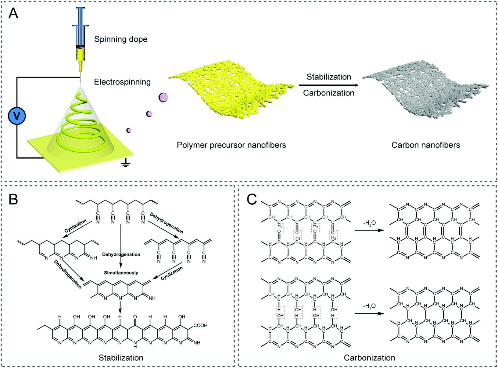 | ||
| Fig. 1 (A) Schematic illustration of the preparation route of electrospun CNFs. Typical chemical reactions in the (B) stabilization and (C) carbonization processes of the PAN precursor.13,17 | ||
| Polymers | Solvents for electrospinning | Cost | Mechanical strength of CNFs | Carbon yield | Advantages or disadvantages |
|---|---|---|---|---|---|
| DMF: dimethylformamide, DMAc: dimethylacetamide, THF: tetrahydrofuran. | |||||
| PAN | DMF | High | High | High | High spinnability |
| PVP | Water, ethanol | Low | Low | Low | Nontoxicity |
| CA | DMAc/acetone, DMF | Low | Low | Low | Ease of production |
| PVA | Water | Low | Low | Low | Environmental friendliness |
| PMMA | DMF | High | Low | Low | Good porogen |
| PI | — | High | High | High | Complicated preparation |
| Pitch | THF/DMF | High | High | High | Low spinnability |
| Lignin | DMF, water | Low | Low | Low | Renewable source |
Carbon materials are among the most employed materials in various energy storage and conversion devices, where they offer the inevitably-required electrical, chemical/electrochemical and mechanical functions, acting as either active materials by themselves or substrate supports for other active materials or both. Taking supercapacitors as an example, they mainly involve two types of working mechanisms, that is, electrical double-layer capacitance (EDLC) and faradaic pseudocapacitance.21 Carbon-based supercapacitors are manipulated mostly in the form of EDLC, in which case energy is stored by the rapid electrostatic charge accumulation at the electrode/electrolyte interface, thus resulting in a superior power density and cycling stability, compared with those of metal oxide/hydroxide- and conducting polymer-based pseudocapacitors that incorporate underpotential deposition, redox reaction and intercalation pseudocapacitance without phase transitions at the surface/subsurface and even inside the electrode.4,22 According to the following formula of EDLC:
 | (1) |
However, the traditional electrospun CNFs derived from PAN precursors, in many cases, suffer from a much lower electrical conductivity, in comparison with graphene and CNTs,27 owing to the incomplete/poor graphitization of PAN even at an extremely high carbonization temperature.28 Besides, the resulting SSA of these electrospun CNFs with a solid interior can be in the range of 10–30 m2 g−1, almost 1–2 orders of magnitude lower than those of graphene and CNTs,29 which largely limit their charge storage ability, especially at the electrode/electrolyte interface. The design of a well-developed porous structure in CNFs would improve their surface areas, but there is a delicate trade-off between the level and type of pores and mechanical robustness, as well as the electrical conductivity. In general, CNFs by themselves often show unsatisfactory electrochemical performance, due to their low theoretical capacitance. Therefore, it is required to rationally improve the degree of graphitization, enlarge the surface area, and control the porosity of the electrospun CNFs, where the desirable mechanical flexibility is also maintained. Carbon-based materials by themselves are largely electrochemically inactive, where for example, un-doped carbon can offer little pseudocapacitance, due to the chemically inert nature. Therefore, to further activate the favorable pseudocapacitance, doping CNFs with various heteroatoms has been widely explored over the past few years, giving rise to an increase in the overall specific capacitance and energy density.
For almost all of their energy applications, mechanical robustness is a key parameter for carbon-based materials. This is especially so, as the new generation energy storage and conversion have been steadily moving into those flexible devices in recent years, where mechanical flexibility is required, in addition to mechanical robustness. As mentioned above, to tune the electrochemical performance of CNFs, one approach is to design a well-developed porous structure, such that their surface area will be improved. However, there is a delicate balance between the level and types of pores and mechanical properties, as well as with the electrical conductivity. On the other hand, to rationally enhance the degree of graphitization in electrospun CNFs, both the electrical conductivity and mechanical flexibility can be improved. Therefore, there can be a rather complicated interplay and/or trade-off among the different key performance parameters of CNFs, when one or more of the structural/compositional features are varied.
Together with the numerous attempts that have been made to elevate the electrochemical performance of carbon-based materials in energy storage and conversion, there are several excellent reviews committed to this interesting and rapidly evolving topic. They primarily focus on graphene, CNTs, mesoporous carbon, and their nanocomposites, for energy-related applications, such as supercapacitors, Li-ion batteries, fuel cells, and hydrogen storage.30–33 Although some of the common issues facing these carbon-based materials have been discussed in these reviews, those specific issues for electrospun CNFs have not been treated properly and exclusively. Indeed, there has been a growing number of studies that are dedicated to the manipulation of electrospun CNFs for high-performance energy storage over the past couple of years, notably for supercapacitors. In this review, we will look into the recent progress made in addressing these key issues faced by electrospun CNFs for their energy applications, where we use supercapacitors as an example, including improving the conductivity, tuning the pore structures, doping with heteroatoms, and reinforcing the mechanical robustness. The basic scientific principles in these activation processes and their effectiveness in boosting the electrochemical performance of CNFs are examined. Finally, some of the challenges and future directions in engineering CNFs for better performance are highlighted.
2. Electrical conductivity
A high enough conductivity for CNFs is of great importance for applications in energy storage devices, such as supercapacitors and batteries. Common CNFs are conductive; however, they are not conductive enough for high performing energy devices. The conductivity of CNFs is strongly related to the degree of graphitization, which can be qualitatively estimated by the ratio of G and D band intensity (IG/ID) in the Raman spectra, where it is positively correlated to the in-plane crystal domain size (La). It is well known that the production of CNFs from the electrospun PAN precursors involves two main steps, one is the stabilization of PAN nanofibers in air at 200–300 °C, and the other is the high-temperature carbonization and graphitization under N2 or Ar flow at 800–3000 °C.34–36 Simply elevating the stabilization and carbonization temperatures in the heat-treatment process can, to some extent, improve the degree of graphitization and crystallinity for the electrospun CNFs.28,35,36 For instance, a higher stabilization temperature above ∼260 °C was found to be in favor of the complete cyclization, dehydrogenation, aromatization, and oxidation reactions of PAN to form a thermally stable conjugated ladder structure along the polymer chain axis with the ability to tolerate the following carbonization conditions.35,37 Similarly, Gupta et al. have demonstrated that both the calculated La and IG/ID values of the PAN-derived CNFs monotonically increase as the carbonization temperature varies from 1000 to 1800, and then to 2200 °C, leading to a rise in electrical conductivity from 5.32 to 51.01 and finally to 75.91 S cm−1.36Unfortunately, as mentioned earlier, the conductivity of the common CNFs is rather low, only reaching a level of tens of siemens per centimeter, even when carbonized at 2800 °C with huge energy consumption.28 A high carbonization temperature also causes the reduction of nitrogen doping concentration in CNFs.38 Tan et al. investigated the dependence of electrochemical performance on the processing temperature for CNFs in detail.39 An optimal specific capacitance of 155 F g−1 was observed at the carbonization temperature of 700 °C, with a pre-oxidation temperature of 280 °C. A balance between the nitrogen doping level and electrical conductivity can be realized by regulating the carbonization temperature, which is the key to achieve a high specific capacitance.
Alternatively, incorporating certain metals, nonmetals and their compounds (catalysts) or other carbon materials into the electrospinning solution has been identified as an effective strategy to improve the conductivity of final CNFs, which can be achieved under mild thermal conditions. In this connection, we will look into two types of additives that strongly influence the structure and conductivity of CNFs, and therefore the resulting capacitive properties, when they are employed in supercapacitors.
2.1 Catalytic graphitization
The catalytic graphitization of CNFs by adding various metals has been practiced, nevertheless it is a rather complex process, as it involves both physical and chemical changes. There are two major understandings:40 (i) transition metals, such as Fe, Co, Ni, etc. can dissolve a degree of amorphous carbon to generate solid solutions, and the catalytic graphitization reactions tend to take place according to the dissolution–precipitation mechanism; (ii) high-valence metals, such as Ti, V, Mo, etc. can be covalently bonded with carbon to result in the formation of carbides, which will then decompose into metal vapors and graphitic carbons at high temperatures; i.e., the catalytic graphitization occurs based on the carbide conversion mechanism. The catalysts used to accelerate the graphitization of CNFs can be in the form of elementary substances, alloys and compounds.41–44 For example, Kim and co-workers added iron(III) acetylacetonate (IAA) and cobalt(II) acetate tetrahydrate into polymer solutions, respectively, for the electrospinning synthesis of CNF-based materials.41,45 The catalytic effects of the metallic Fe and Co expedited the graphitization of the local CNFs at a relatively low temperature of 650 °C, as a consequence, giving rise to a satisfactory electrical conductivity. Bimetallic MCo (M = Cu, Fe, Ni, and Mn) alloy nanoparticles have also been doped into the electrospun CNFs, which exhibit a higher degree of graphitization than the pristine CNFs, as evidenced by the larger IG/ID values.42 Similarly, the introduction of compounds like α-Fe2O3 into CNFs helps create more ordered graphitic crystallites of carbon (sp2-hybridized).43With the numerous research studies that have been made in the catalytic graphitization of CNFs to enhance their conductivity, one of the applications is in all-carbon supercapacitors. Highly flexible porous carbon nanofiber (PCNF) films could be fabricated by electrospinning in combination with a metal etching process (Fig. 2A–E), which not only showed a large SSA, but also an improved conductivity, due to the high degree of graphitization caused by metal Co catalysis in thermal treatments.29 When employed as supercapacitor electrodes, the freestanding PCNFs gave rise to a specific capacitance of 104.5 F g−1 (0.2 A g−1) and a rate capability of 56.5% (10 A g−1), both comparing favorably with the conventional CNF electrodes. Furthermore, the assembled symmetric supercapacitors delivered excellent flexibility and an energy density of 3.22 W h kg−1 at a power density of 600 W kg−1 (Fig. 2F–M). Similarly, Zhang et al. prepared the hierarchical PCNFs (HPCNFs) via electrospinning, calcination, and the subsequent acid corrosion utilizing CaCO3 nanoparticles as both the catalysts and templates.44 The degree of graphitization, electrical conductivity, and SSA of HPCNFs were all increased, especially with a uniform dispersion of nano-CaCO3. As a binder-free electrode for supercapacitors, the HPCNFs displayed a high specific capacitance of 251 F g−1 (0.5 A g−1), an outstanding rate performance of 63.7% (20 A g−1), and a good cycling stability with the capacitance retention of over 88% after 5000 cycles.
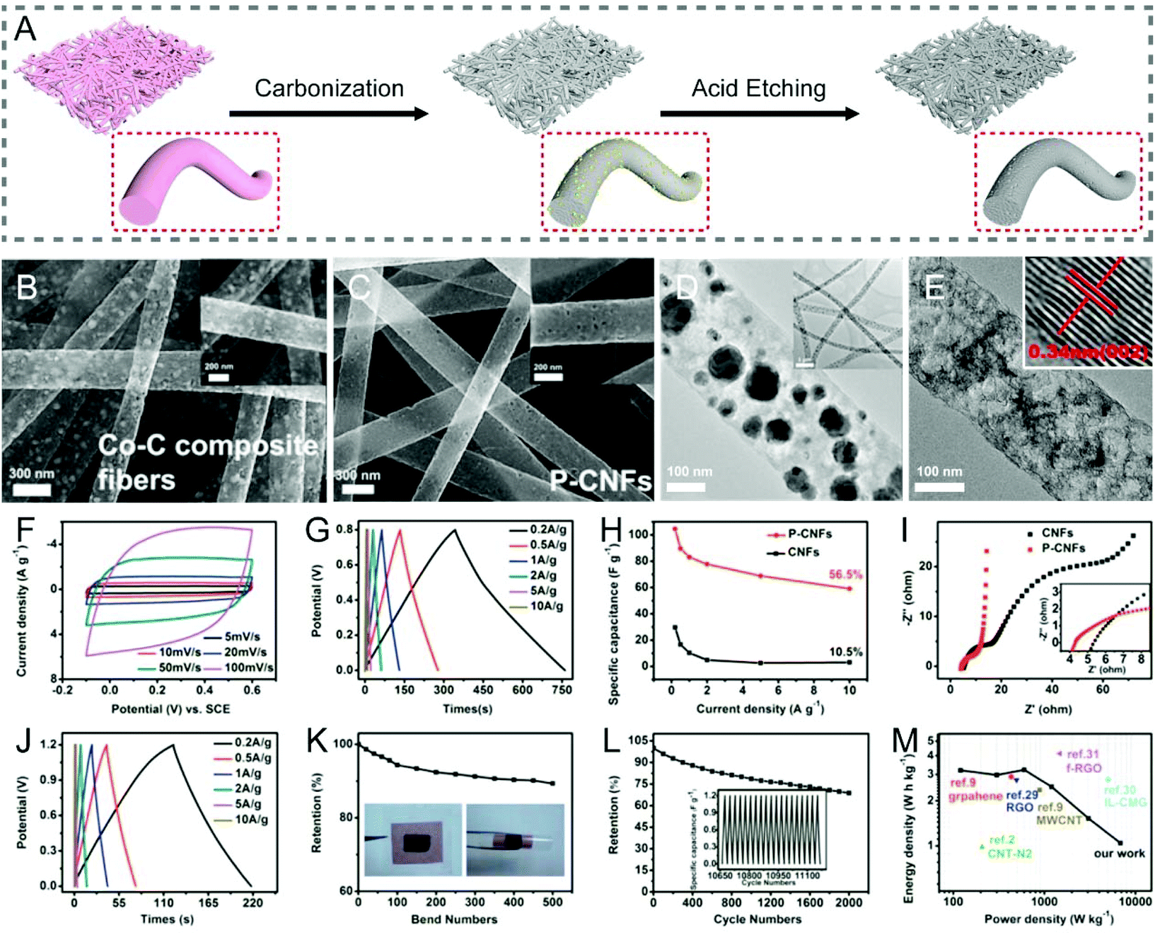 | ||
| Fig. 2 (A) Schematic illustration of the fabrication of PCNFs with a high degree of graphitization by metal Co catalysis during thermal treatments. (B and C) SEM and (D and E) TEM images of (B and D) Co–C composite fibers and (C and E) PCNFs. Inset in (E): The interplanar spacing of PCNFs. Electrochemical performance of PCNFs measured in (F–I) three-electrode and (J–M) two-electrode systems: (F) CV curves at various scan rates, (G and J) GCD profiles at different current densities, (H) specific capacitance as a function of current density, (I) Nyquist plots, (K) capacitance retention of the symmetric device for bending cycles, (L) cycling performance, and (M) Ragone plots. Reproduced with permission from ref. 29. Copyright 2015, American Chemical Society. | ||
In addition to the above metal-based species, some nonmetals have also been demonstrated to be graphitization catalysts for CNFs. For example, boron is one of the canonical candidates, which can substitute a fraction of carbon atoms in the carbon networks and form a B2O3 layer at high doping concentrations, thereby accelerating the graphitization of carbonaceous materials.46,47 Indeed, boron-doped CNFs have been widely explored as supercapacitor electrodes in recent years, whereas, considerable attention is paid to the porous structure and extra pseudocapacitance of CNFs contributed by boron doping. More discussions on heteroatom doping will be presented in section 4. Similar to other carbon-based materials, the catalytic graphitization can give rise to strengthening in mechanical properties, with an increased fraction of graphitic carbon and minimized structural defects in electrospun CNFs.
2.2 Integration with other carbon forms
The introduction of graphene, CNTs, and other types of carbon materials into the electrospun CNFs not only promotes the electrical conductivity, but also affects the overall architecture, hence boosting the electrochemical properties. Typical examples including graphene-beaded CNFs,48–54 CNT-reinforced porous CNFs,55–57 graphene/CNT-embedded CNFs,58 carbon black-doped porous CNFs,59 and activated carbon nanowhisker-wrapped graphitized CNFs have been reported,60 which show better capacitive performance than that of CNFs alone as described in Table S1.†However, only a slight increase in conductivity has been achieved by the incorporation of a conductive component into the CNF precursors. For instance, the electrospun CNF hybrids containing 0.8 wt% of multiwalled CNTs exhibited a minor improvement in conductivity from 0.86 to 5.32 S cm−1, compared with that of the pristine CNFs.61 Besides, a higher content of additives usually leads to a poor electrospinnability of the precursor solution.27 Post-chemical modification of electrospun CNFs with graphene or CNTs may be a promising way to construct certain nanostructures with enhanced electrochemical performance and/or novel functionalities, e.g., pseudocapacitive behavior.62–67 Graphene-linked CNF composite aerogels were fabricated via the surface-induced co-assembly of pre-oxidized electrospun PAN and graphene oxide (GO), and the subsequent carbonization, which led to an improvement in electrochemical properties, as a result of the interconnected macropores and conductive networks.64 Vertically aligned CNTs were directly grown on the electrospun CNF backbones,65 where these hierarchical three-dimensional (3D) nanostructures possessed high conductivity and large SSA, thus boosting the charge transfer and ion diffusion.
3. Porous structures
For applications in EDLC-based supercapacitors, which depend on ion diffusion and adsorption for operation, CNFs preferably possess multi-scale pores, i.e., the combination of micropores (<2 nm), mesopores (2–50 nm), and macropores (>50 nm). Therefore, rationally electrospun CNFs shall be made with a hierarchical porous structure, providing an enlarged SSA for charge adsorption and abundant reservoirs accessible for electrolyte ions.68,69 In this section, we will examine some of the most representative approaches to create different types of pores and their incorporation into electrospun CNFs for enhanced charge storage performance.3.1 Template approaches
The template method is one of the most popular strategies to precisely control the pore structure of CNFs, through tailoring either the type or the dosage of templates. Typically, a template in powder form is mixed evenly into the polymer solution used for electrospinning, or the carbon precursor is deposited on an electrospun nanofibrous template at first, and the porous CNFs can then be obtained via the carbonization treatment, followed by removing the templates. The commonly-used templates can be divided into inorganic and organic species.Metals and their oxides are the alternatives to SiO2 templates, as most of them can be readily removed by diluted acids. Foamed porous CNFs composed of well-connected ultrathin carbon nanobubbles were obtained by coating ethanol-derived carbon on electrospun ZnO nanofibers followed by a reduction–evaporation process to remove the ZnO templates (Fig. 3A–C).74 The integrated CNF webs with excellent flexibility were directly employed as the working electrodes, which displayed an acceptable specific capacitance of 150 F g−1 (0.5 A g−1), a high rate capability of 62.0% (0.5–70 A g−1), and a long cycling life of 35![[thin space (1/6-em)]](https://www.rsc.org/images/entities/char_2009.gif) 000 cycles (94.1% capacitance retention) in a three-electrode configuration (Fig. 3D–G). These electrochemical performance parameters can be well correlated to the interconnected bubbled structure in the porous CNF membranes. Interestingly, electrospun SnO2/Fe2O3 composite nanofibers were also adopted as the templates for the manufacture of inner porous CNFs with polydopamine as the carbon source.75 The corresponding electrode presented outstanding capacitive properties benefited from the large SSA and intrinsic nitrogen doping of CNFs. In connection with the above unique synthesis strategy, porous CNFs are generally fabricated through the carbonization of the electrospun polymer/template composite nanofibers. Despite the advantage of being apt to remove, nanoparticles of metals and their oxides tend to aggregate and form precipitates in the spinning solution, which can result in the blockage of the spinneret and the uneven distribution of the template particles in the polymer backbones. Therefore, it would be necessary to prepare uniform precursor solutions by using certain surfactants and the constant stirring or vigorous ultrasonic treatments.
000 cycles (94.1% capacitance retention) in a three-electrode configuration (Fig. 3D–G). These electrochemical performance parameters can be well correlated to the interconnected bubbled structure in the porous CNF membranes. Interestingly, electrospun SnO2/Fe2O3 composite nanofibers were also adopted as the templates for the manufacture of inner porous CNFs with polydopamine as the carbon source.75 The corresponding electrode presented outstanding capacitive properties benefited from the large SSA and intrinsic nitrogen doping of CNFs. In connection with the above unique synthesis strategy, porous CNFs are generally fabricated through the carbonization of the electrospun polymer/template composite nanofibers. Despite the advantage of being apt to remove, nanoparticles of metals and their oxides tend to aggregate and form precipitates in the spinning solution, which can result in the blockage of the spinneret and the uneven distribution of the template particles in the polymer backbones. Therefore, it would be necessary to prepare uniform precursor solutions by using certain surfactants and the constant stirring or vigorous ultrasonic treatments.
 | ||
| Fig. 3 (A) Schematic of the synthesis of foamed PCNFs using electrospun ZnO nanofibers as the templates. (B) SEM and (C) TEM images of the single foamed PCNFs composed of well-connected ultrathin carbon nanobubbles. (D–G) Electrochemical performance of the corresponding electrode in the three-electrode system: (D) CV and (E) GCD curves at different scan rates and current densities, respectively. (F) Changes of specific capacitance along with current density. (G) Cycling stability. Inset: SEM image of the PCNFs after 35000 cycles. Reproduced with permission from ref. 74. Copyright 2017, Royal Society of Chemistry. | ||
Given that many inorganic salts can be dissolved in the polymer precursor solutions, they are more versatile than the metal oxide templates for the engineering of porous CNFs. Considering their reaction types in the pyrolysis steps, inorganic salt templates can be mainly divided into two categories: one is the stable template and the other is the decomposable template.69 For the former, ionic compounds, such as NaCl, KCl, K2CO3, K2S, etc. with high thermal stability that remains unchanged, fall into this category.76–78 For the latter, the inorganic salts usually decompose into metal oxides or metals during the pyrolysis process of carbon precursors, serving as the hard templates to yield mesopores or macropores. To date, numerous decomposable salt templates have been developed for the preparation of porous CNFs, including CaCO3, NaHCO3, Co(NO3)2, Mg(NO3)2, Mg(OH)2, SnCl2, ZnCl2 and so on.29,44,79–89 Some of them, namely, CaCO3 decomposing into CaO and Co(NO3)2 converting to Co, can also act as the catalysts to accelerate the graphitization of the porous CNFs.29,44,81 NaHCO3 is a special case, which begins to resolve into Na2CO3, CO2 and H2O at 50 °C, and then turns into Na2O at higher temperatures. The as-formed Na2O can be easily removed by immersing it in water, giving rise to the creation of stable and homogeneous mesopores in CNFs.80 Mai et al. have developed in situ nitrogen-doped mesoporous CNFs (N-MCNFs) by electrospinning PAN/Mg(OH)2 composite nanofibers, followed by carbonization and etching.84 The flexible N-MCNF network possessed better water wettability and higher SSA (926.40 m2 g−1) than the conventional electrospun CNFs, due to the introduction of the Mg(OH)2-derived MgO template, which meets the general requirements of an ideal EDLC-based electrode material (Fig. 4A–K). As a result, the freestanding N-MCNFs showed a large capacity of 327.3 F g−1 (1 A g−1), a good rate capability of ∼68% (20 A g−1), and a high capacitance retention of ∼93% after 10000 cycles (Fig. 4L–O).
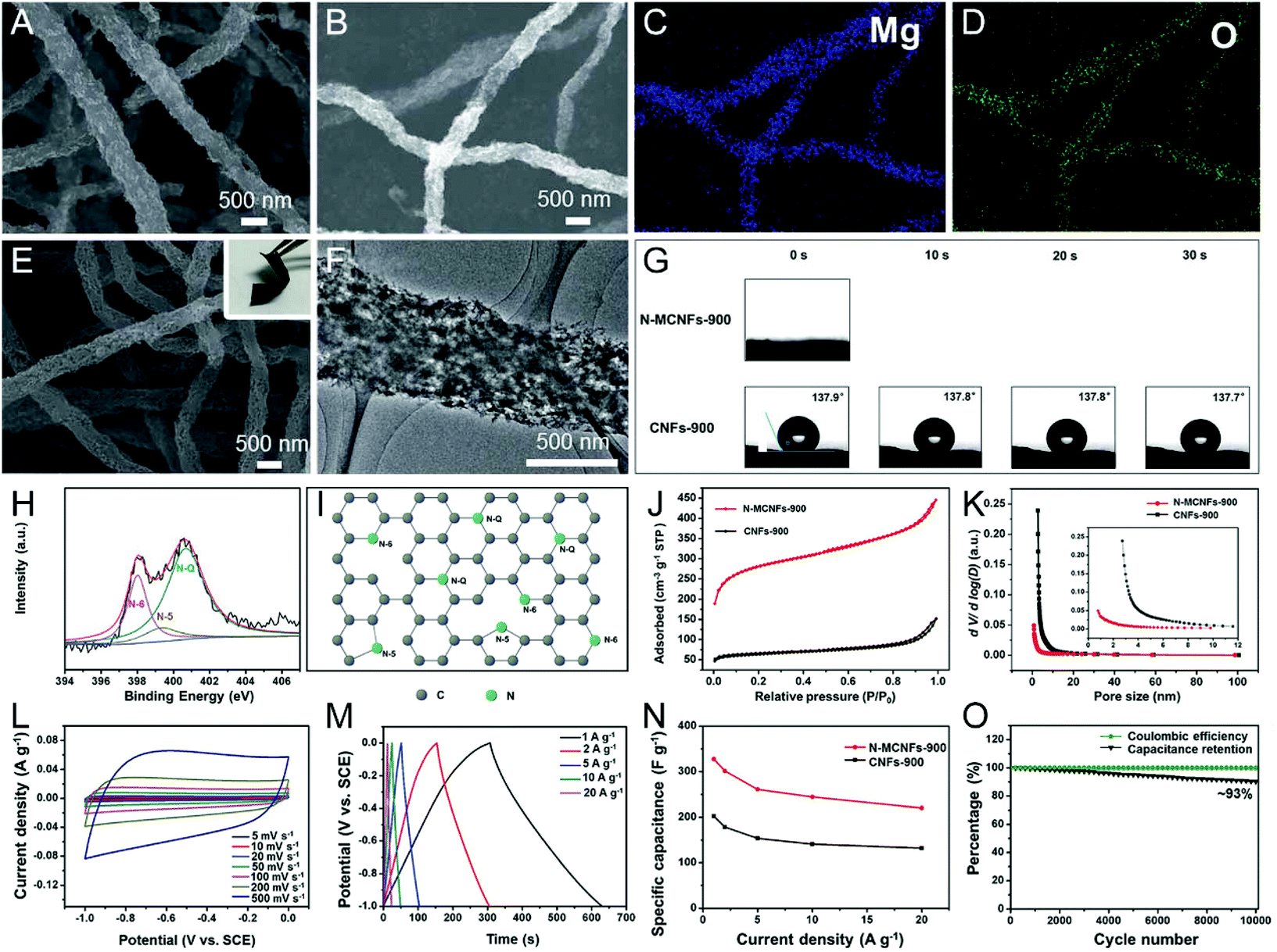 | ||
| Fig. 4 (A) SEM image and (B–D) elemental mappings of the PAN/Mg(OH)2 nanofibers carbonized at 900 °C. (E) SEM and (F) TEM images of the flexible N-MCNF network. (G) Dynamic water contact angle tests. (H) High-resolution N 1s XPS spectra of N-MCNFs. (I) Possible locations for N atoms in the carbon network. (J) N2 adsorption–desorption isotherms and (K) pore size distribution (PSD) diagram. (L–O) Electrochemical performance of the N-MCNFs using a three-electrode configuration: (L) CV and (M) GCD curves, (N) specific capacitance at various current densities. (O) Cycling durability and coulombic efficiency of N-CNFs at 20 A g−1. Reproduced with permission from ref. 84. Copyright 2017, Royal Society of Chemistry. | ||
TEOS is transformed into SiO2 by an appropriate thermal treatment, which however is different from SiO2 templates, as it is soluble in the spinning solution, rendering the uniform and tunable porous architectures of CNFs.90–96 Cui and co-workers reported the bamboo-like graphitic CNFs with periodically distributed hollow interiors along the longitudinal orientation and hierarchical hole structures in the lateral direction, which were obtained by electrospinning, carbonization, and etching treatments using PAN and TEOS as the carbon precursor and porogen, respectively (Fig. 5A–F).90 The well-balanced macro-, meso- and micropores in the fibers enhanced their mechanical durability, and facilitated ion penetration, thus leading to the excellent electrochemical performance of the flexible all-solid-state supercapacitor, tested even under continuous dynamic bending (90°) and twisting (180°) operations (Fig. 5G–M).
 | ||
| Fig. 5 (A) Schematic of the preparation process of the bamboo-like CNFs. TEM images of (B) the TEOS/PAN nanofibers, (C) SiO2/carbon nanofibers, and (D) bamboo-like CNFs. (E) SEM and (F) HRTEM images of the resulting bamboo-like CNFs. (G) Mechanical properties. (H and I) Three-electrode measurements: (H) GCD curves and (I) specific capacitance as a function of current density. (J–M) Electrochemical performance of the all-solid-state flexible supercapacitor: (J) GCD curves, (K) cycle life, (L) digital images of the device bended by (1) 0 and (2) 90° as well as twisted by (3) 90 and (4) 180°, and (M) the related CV curves and capacitance retention. Reproduced with permission from ref. 90. Copyright 2015, American Chemical Society. | ||
Metal acetates, such as Zn(Ac)2, Ni(Ac)2, Mg(Ac)2, Cu(Ac)2, etc., are frequently-used organic salt templates.97–101 Their pore-forming mechanism is the same as that of decomposable inorganic salts. Hu et al. presented a simple Zn(Ac)2-assisted electrospinning–peroxidation–carbonization method for the production of foldable CNFs (FCNFs), where Zn(Ac)2 was demonstrated to enhance the mechanical flexibility of FCNFs, by relieving the stress concentration and creating porous structures.97 During the carbonization process, ZnO was generated in situ from the decomposition of Zn(Ac)2, which could oxidize the local carbon to form pores and defects, accompanied by the removal of ZnO itself (ZnO + C → Zn↑ + COx↑). As a self-supported electrode, the fabricated FCNFs delivered an overall excellent electrochemical performance.
Metal complexes, including metal–organic frameworks (MOFs), iron(III) acetylacetonate, tin(IV)-citric, etc., are composed of metal ions/clusters and organic linkers/ligands, which can be decomposed or reduced to metal/metal oxide nanoparticles and carbon species by pyrolysis.41,102–110 Among them, MOFs have been widely applied as the organic templates for the construction of porous or hollow CNFs, due to their largely controllable structures, pore types and levels.111,112 There are two main synthesis approaches: (i) polymer/MOF solution is electrospun to form nanofibers followed by the carbonization and subsequent removal of templates; (ii) MOFs are deposited in situ or by polarity induction on the electrospun polymer nanofibers, and then the core–shell 1D heterostructures are converted into porous or hollow CNFs. For example, Lou et al. designed a type of hierarchical porous nitrogen-doped CNF (HPCNF-N) assembled with interconnected carbon hollow nanoparticles by carbonizing the electrospun zeolitic imidazolate framework (ZIF-8)/PAN composite precursor (Fig. 6A–G).102 The SSA of the resulting HPCNFs-N was 417.9 m2 g−1 (Fig. 6H), which was much higher than that of the solid PAN-derived CNFs (8.7 m2 g−1), indicating the importance of incorporating the ultrafine ZIF-8 nanoparticles. Thanks to its unique porous architecture and high nitrogen-doping level, the as-prepared supercapacitor device based on the HPCNF-N sample exhibited a remarkable specific capacitance of 307.2 F g−1 (1 A g−1), a maximum energy/power density of 10.96 W h kg−1/25000 W kg−1, and a desirable cycling durability with 98.2% capacitance retention over 10000 cycles (Fig. 6I–M). There are other examples of similar work that will not be listed here.105–108 More recently, Gong et al. developed a versatile polarity-induced method to decorate a monolayer sheath of MOFs on the electrospun polymer nanofibers.109 The surface functional groups of the employed polymers were found to have a great effect on the loading capacity and uniformity of ZIF-8 nanoparticles, where they followed the order of PAN > PVA > polylactic acid (PLA), due to the higher polarity of –CN on the side chain of PAN than those of –C–OH on PVA and –C![[double bond, length as m-dash]](https://www.rsc.org/images/entities/char_e001.gif) O on PLA. This general approach could also be expanded to the growth of other types of MOFs on the electrospun PAN nanofibers, such as Cu-BTC (trimesic acid), Ni-2-MIM (2-methylimidazole), Ni-BTC, and Mn-BTC. The PAN@ZIF-8 nanofibers were then transformed into nitrogen-doped porous CNFs with a conductive carbon core and a monolayer coating of hollow carbon frames, which yielded superior electrochemical performance when used as the supercapacitor electrodes.
O on PLA. This general approach could also be expanded to the growth of other types of MOFs on the electrospun PAN nanofibers, such as Cu-BTC (trimesic acid), Ni-2-MIM (2-methylimidazole), Ni-BTC, and Mn-BTC. The PAN@ZIF-8 nanofibers were then transformed into nitrogen-doped porous CNFs with a conductive carbon core and a monolayer coating of hollow carbon frames, which yielded superior electrochemical performance when used as the supercapacitor electrodes.
 | ||
| Fig. 6 (A) Schematic illustration of the fabrication of HPCNFs-N. (B and D) SEM and (C and E) TEM images of (B and C) the PAN/ZIF-8 nanofibers and (D and E) HPCNF-N sample. (F) HRTEM images, (G) elemental mappings, and (H) N2 adsorption–desorption isotherms and PSD curves of HPCNFs-N. (I–M) Electrochemical performance of HPCNFs-N in a two-electrode cell configuration: (I) CV and (J) GCD profiles. (K) Variation of specific capacitance against current density. (L) Cycling properties. Inset: SEM image of the HPCNF-N electrode after 10000 cycles. (M) Ragone plots of HPCNFs-N and other carbon-based devices. Reproduced with permission from ref. 102. Copyright 2017, Royal Society of Chemistry. | ||
Certain bicomponent or multicomponent polymers are often mixed together and used as the electrospinning precursors for the preparation of porous, hollow or multichannel CNFs, considered for their different thermal stabilities and solubilities. Typical polymer hybrids are PAN/PVP, PAN/PMMA, PAN/PS (polystyrene), PAN/PEO (polyethylene oxide), PAN/CA, PAN/PSF (polysulfone), PAN/PVDF (polyvinylidene fluoride), PAN/APEG (allyl polyethylene glycol), PAN/pitch, PAN/PmAP (poly(m-aminophenol)), PAN/pluronic F127, PAN/Nafion, PI/PVP, PAN/PMMA/TPU (thermoplastic polyurethane), PAN/lignin/pluronic P123, etc.113–152 For example, PVP, as both a porogen and nitrogen/carbon source, is a commonly-used polymer template for the fabrication of hierarchical porous CNFs with micropores, mesopores and/or macropores. Li et al. developed a non-woven network of porous nitrogen-doped CNFs (PNCNFs) via electrospinning PAN/PVP precursors, followed by stabilization and carbonization.113 The PNCNFs delivered a high specific capacitance, when measured in a three-/two-electrode configuration, due to their abundant interface active sites and hierarchical pores for solvated ions. In addition to being a self-template, the PVP in electrospun PAN/PVP composites can be easily extracted by hydrothermal treatment, ultrasonic-assisted vibration or leaching in hot water to form porous PAN precursor nanofibers, which would be further converted into CNFs with well controlled hierarchical pores or hollow structures.114,115,117,118 Polymers do have some advantages as the organic templates, owing to their wide varieties, ease of removing, desirable pore-forming ability, and low cost. However, the spinnability and complicated pretreatments of some fossil/biomass polymers, such as pitch, coal, lignin, and CA, should be taken into consideration.
Other organic compounds, such as terephthalic acid (TPA), melamine, and itaconic acid (IA), have also been explored as templates to in situ create pores on/in the electrospun CNFs, the formation mechanisms of which are based on the sublimation of TPA as well as the decomposition of melamine and IA during pyrolysis.153–155 The cross-linked CNF networks with a hierarchical porous architecture derived from the PAN/TPA composite fibers could be employed as flexible supercapacitor electrodes.153 The assembled solid-state device delivered a maximum energy density of 10.18 W h kg−1 and a high capacitance retention of 95% after 20000 cycles. Similar to most polymer porogens, although these organic molecules can effectively produce pores on/in the CNFs and also improve their SSA, the quality of the resulting carbons, especially referring to the degree of graphitization or conductivity, is inferior to that of the electrospun CNFs using metal-containing species as the templates.
In order to further regulate the pore structure of electrospun CNFs, dual templates of different types are introduced into the carbon source precursors, where lignin/PVP/Mg(NO3)2, PAN/PVP/TPA, PAN/PVP/silicone oil, phenolic resin/PVP/pluronic F127/Mg(NO3)2, and lignin/PEO/TEOS/PVP are typical examples.83,92,156–158 Wang et al. designed the double-capillary CNFs using coaxial electrospinning, where the inner solution was lignin/PEO/DMF and the outer fluid was TEOS/PVP/ethanol (Fig. 7A and B).92 The as-prepared CNFs with micropores and mesopores in the core and shell layers, respectively, helped achieve rapid ion diffusion, high conductivity, and good flexibility. The assembled binder-free supercapacitors displayed a supreme energy density of 56.6 W h kg−1 and a maximum power density of 114 kW kg−1 in the ionic liquid electrolyte (Fig. 7C–J).
 | ||
| Fig. 7 (A and B) Schematic of the preparation process for the double-capillary CNFs (DCNFs) using coaxial electrospinning. (C) SEM and (D) TEM images of DCNFs. Insets are the digital photograph of the flexible DCNF membrane and the illustration of the porous structure. (E) N2 adsorption–desorption isotherms and (F) PSD curves. (G–J) Electrochemical performance measured in a two-electrode system: (G) Nyquist plots, (H) Ragone plots, (I) digital images of the DCNF-based device bent by 0 and 90°, and (J) the corresponding CV curves. Reproduced with permission from ref. 92. Copyright 2016, Elsevier. | ||
3.2 Etching approaches
Porous CNFs derived from the template methods often contain meso- and macropores. In some cases, the dehydration and dehydrogenation of organic compounds during the pyrolysis process can also lead to the formation of micropores at a low level.159 To increase the amount of micropores, which are known to benefit the ion accessible surface area and capacitance, activation treatments are frequently implemented by using various types of carbon-corrosion agents, such as oxidizing gases (air, CO2, and steam),4,48,56,67,116,124,160–174 acids and alkalis (H3PO4, KOH, etc.).122,137,138,140,143,145,157,175–182 A well-controlled etching treatment can give rise to a hierarchical porous carbon structure, as has been extensively reported.Recently, the activation of CNFs with steam has been summarized in a review by Lu et al.4 In addition to the mentioned PAN, PBI, and PI,168–172 polymers of intrinsic microporosity (PIM-1) can also be used as the electrospinning precursors to prepare ACNFs by the steam activation process.173 The BET surface area of the flexible ACNFs reached up to 1162 m2 g−1, which was more than twice that of the unactivated CNFs (546 m2 g−1). These porous ACNFs, as binder-free supercapacitor electrodes, provided a specific capacitance of 149 F g−1, an energy density of 60 W h kg−1, and a powder density of 1715 W kg−1 at the current density of 1 A g−1 in a symmetric two-electrode cell with ionic liquid as the electrolyte. The excellent electrochemical performance of the freestanding ACNFs makes them potentially good electrode materials for high energy/power applications. Steam has also been involved in the activation of PAN-coal based CNFs,174 where the obtained ACNFs with the mass ratio of PAN to coal at 5:5 delivered a large specific capacitance of 230 F g−1 (1 A g−1) and a high capacitance retention of 97% (1000 cycles).
It is reported that physical activation reduces the fiber diameter, and improves the total pore volume and SSA of CNFs in the order of the oxidation reactivity with carbon: H2O > CO2 > N2 (800 °C).160 Compared with inert N2, the oxidative atmospheres of H2O and CO2 lead to an increase in micropore size. Moreover, the porous CNFs activated by H2O possess poorer conductivity and a lower nitrogen-doping level than those treated with CO2 and N2. As a result, the H2O-activated porous CNFs, when used as supercapacitor electrodes, show the lowest capacitance among the three samples.
KOH has been known as an activating agent for carbon-based materials for more than 40 years, and it is extensively used among various chemical reagents, as it can result in the generation of micropores and small mesopores in carbon frameworks.176 The activation mechanism by KOH is complex and dependent on both the experimental parameters (i.e. the concentration of KOH, activation temperature, time, etc.) and the reactivity of carbon sources, and also there remain some unsolved issues. Even so, a commonly acknowledged understanding is the expansion of the carbon lattice caused by the metallic K intercalation, which originates from the dehydration and reduction of KOH.176,179
The SSA and total pore volume of the electrospun PAN-derived CNFs were found to increase as the KOH activation temperature increased from 600 to 1000 °C, leading to a dramatic enhancement in specific capacitance.177 The carbon yield of CNFs was only 5.7% when activated at 1000 °C, and lower than 1% at higher temperatures. Besides, the KOH uptake has a significant influence on the porous architecture and surface chemistry of CNFs. Ma et al. fabricated CNF papers by the KOH etching and subsequent carbonization of electrospun phenolic-based nanofibers.179 They discovered that when the concentration of KOH solution increased from 0 to 20 wt%, the SSA of the activated CNFs was enlarged from 524 to 1317 m2 g−1, the total pore volume was improved from 0.228 to 0.699 cm3 g−1, the average pore width was increased from 1.74 to 2.12 nm, and the oxygen content was elevated from 9.7 to 15.1 at%. As binder-free supercapacitor electrodes, the porous CNF papers treated with 20 wt% KOH exhibited a maximum capacity of 362 F g−1 (0.2 A g−1), an outstanding rate capability, and favorable energy densities in both aqueous and organic electrolytes.
Similarly, the specific capacitance of the porous CNFs activated by H3PO4 (0–1 wt%) and ZnCl2 (2–20 wt%) increased along with the increase in the mass percentage of activating agents, due to the sequential increase in SSA and total pore volume.181,182 A maximum energy density of 21.46 W h kg−1 was achieved for the 1 wt% H3PO4-activated CNFs at a power density of 500 W kg−1, and even at an extremely high power density of 10000 W kg−1, the energy density could still reach 10.98 W h kg−1, which was ∼9 times larger than that of the unactivated CNF electrode.181 The 20 wt% ZnCl2-treated CNFs displayed superior electrochemical performance, with a large specific capacitance (202 F g−1 at 0.1 A g−1), a high rate capability (61% capacitance retention from 0.1 to 20 A g−1), and a good cycling stability (92% of the initial capacity after 5000 cycles).182
Having looked into the two general approaches to tailor the pore structure and surface conditions of electrospun CNFs, we examine their impact on the overall electrochemical performance, when employed as the electrodes in supercapacitors. Nevertheless, they involve several inter-connected key parameters. On the one hand, a properly engineered pore configuration will increase the surface area, create transport channels for electrolyte ions/charges, and increase the activity. On the other hand, it will also strongly affect the overall conductivity, which is also a key parameter for electrospun CNFs as discussed above. In general, an improperly designed porous structure would degrade the mechanical properties and flexibility, which are the separate and also key parameters in the overall equation.
4. Heteroatoms and electrochemical activity
Chemical doping of carbon skeletons with heteroatoms, including but not limited to the nonmetallic elements of boron, nitrogen, oxygen, fluorine, phosphorus, and sulfur, could manipulate the electronic structure and surface chemistry of the host carbonaceous materials,68,183 and thus enhance their electrochemical activity. Boron/nitrogen doping is identified as a substitutional doping, which refers to the replacement of certain carbon atoms in the sp2-hybrid lattice by the foreign atoms. Similar to boron/nitrogen, fluorine doping could also result in charge redistribution among carbon atoms owing to the large electronegativity difference between them.184 It is a subject of argument as to whether the phosphorus/sulfur doping belongs to the substitutional doping or not.183,185–187 The oxygen-containing functional groups, e.g., hydroxyl, carboxyl, carbonyl, and epoxy groups, that are chemically grafted on the surface of carbons could improve the hydrophilicity/wettability of materials and introduce additional active sites to electrodes.There are two versatile preparation strategies for heteroatom-doped CNFs, namely, in situ doping and post doping.187,188 As the name suggests, in situ doping is conducted by the direct carbonization of electrospun polymer precursors containing heteroatoms, while for post doping, it is implemented by the post treatment of electrospun CNFs in the presence of targeted heteroatom sources. This section will elaborate the synthesis of heteroatom-doped CNFs with single- or multi-element doping configurations, and their electrochemical performance thus derived.
4.1 Single doping
Nitrogen doping is the most representative strategy to tailor the electrochemical reactivity, conductivity, and wettability of electrospun CNFs through the active sites, free electrons, and C–N polar bonds generated by the four nitrogen functionalities, that is, pyridinic N (N-6), pyrrolic N (N-5), quaternary/graphitic N (N-Q), and pyridinic N oxide (N-X).68,186As has been introduced above, nitrogen-doped CNFs (NCNFs) can be realized by either co-heat treatment or post-processing methods. There are a variety of nitrogen-enriched precursors available for the direct solution electrospinning, such as PAN, PVP, pitch, etc.129,189–191 Some nitrogen-containing additives (e.g., g-C3N4, Li3N, and NH4Cl) can also be incorporated into the electrospinning process for further regulation of the nitrogen doping level.192–195 For polypyrrole (PPy), polyaniline (PANi), PI, polydopamine (PDA), and branched polyethylenimine (bPEI), they are usually post-polymerized or chemically grafted on the electrospun polymer nanofibers, and then undergo a carbonization treatment to obtain hollow NCNFs or to form nitrogen-doped carbon layers on the surface of CNFs.196–200 For example, the authors’ research group designed flexible NCNFs using the electrospun PAN@bPEI nanofibers as the precursors, which delivered superior specific capacitance compared to the pure PAN-derived CNFs, when tested in a three-electrode system (Fig. 8A–E). The quasi-solid-state symmetric supercapacitor based on the binder-free NCNF electrodes exhibited a maximum energy density of ∼8.0 W h kg−1 at the power density of 300 W kg−1 and an excellent mechanical stability with a slight capacitance loss of 8.1% at a high bending angle of 180° (Fig. 8F–H).200
 | ||
| Fig. 8 (A) Schematic illustration of the synthesis of the NCNFs derived from PAN@bPEI. (B) SEM image and (C) high-resolution N 1s XPS spectra of the obtained NCNFs. (D) CV and (E) GCD curves of the NCNFs and the pure PAN-based CNFs in a three-electrode configuration. (F) Ragone plot, inset: schematic of the symmetric supercapacitor. (G) CV curves of the flexible device at different bending levels. (H) Variations of specific capacitance and capacitance retention with bending angles. The inset shows the associated GCD profiles. Reproduced with permission from ref. 200. Copyright 2019, Elsevier. | ||
The post-processing of electrospun polymer nanofibers at high temperatures under NH3 or N2 atmospheres could result in the formation of NCNFs.120,201–204 The nitrogen atoms in NCNFs are deemed to originate mainly from PAN molecules, and partially from the ambient NH3.202 By comparison, the NCNFs carbonized in NH3 possess a higher nitrogen content than that treated with the inert N2 under the same conditions.202 However, NH3 gas with a pungent smell is chemically aggressive and poisonous, which would need extra control as far as safety is concerned. Urea is another effective nitrogen source to prepare NCNFs. For example, He et al. fabricated freestanding NCNFs from the lignin/PEO blend via electrospinning, carbonization, and annealing in the presence of urea.205 Although the nitrogen doping level can be easily controlled by tailoring the calcination temperature, there is little clear relationship between the nitrogen content and electrochemical performance of the NCNFs since the graphitization degree, surface area, and pore structures change along with the variation of pyrolysis temperature.
4.2 Dual doping
Nitrogen-rich PAN is a commonly-used polymer precursor for the preparation of CNFs by electrospinning, which inevitably leads to the partial retention of nitrogen in CNFs. Therefore, in a strict sense, electrospun CNFs are doped with nitrogen already, and doping with another single heteroatom (e.g., boron, oxygen, phosphorus, sulfur, etc.) gives rise to dual doping in CNFs. Compared with single nitrogen doping, dual doping can further improve the electrochemical activity of CNFs by the synergistic effect in boosting the active sites, redox reactions, electron transport, and wettability of the electrode.The electron-deficient element boron is a p-type dopant for carbon, and doping carbon with boron downshifts the Femi level toward the valence band, which induces charge redistribution among the carbon matrix.183 At a low level of boron doping concentration, there is a catalytic effect of boron on carbon oxidation, helping to enhance the hydrophilicity and incorporate extra pseudocapacitance.68 To date, various boron sources have been developed for the fabrication of boron/nitrogen co-doped CNFs, including ammonium hydrogen borate trihydrate (NH4HB4O7·3H2O), ammonia borane (NH3·BH3), boric acid (H3BO3), etc.107,206,207 Kim et al. fabricated boron/nitrogen co-doped 3D PCNFs through electrospinning, solution impregnation (sodium borohydride (NaBH4) followed by NH4HB4O7·3H2O), freeze drying, and carbonization treatment, which were then employed as supercapacitor electrodes, and yielded a specific capacitance of 295 F g−1 at 0.5 A g−1, much higher than that of the single nitrogen-doped CNFs (126 F g−1), due to the enlarged SSA and better wettability in the aqueous electrolyte.107
Oxygen element is almost always present in electrospun CNFs, resulting from the incomplete graphitization under normal carbonization conditions. On the one hand, the oxygen functionalities on CNFs can improve the hydrophilicity and add the redox active sites, but on the other hand, excessive oxygen-containing functional groups would reduce the conductivity and cycle lifespan of CNFs. Although the oxygen doping content has a great impact on the electrochemical performance of carbon materials, few studies have addressed this key issue up to now. Several effective post-treatment strategies have been reported to regulate the oxygen doping concentration in CNFs, e.g., nitric acid (HNO3) oxidation, microwave-assisted oxidation, plasma oxidation, and the physical activation methods as mentioned in section 3.2.1.208–212 As the HNO3 treatment time increased from 0 to 5 h, the oxygen/carbon (O/C) ratio on the fiber surface was increased significantly from 6.0% to 22.4%, while the SSA was decreased from 247 to 165 m2 g−1. The specific capacitance of the oxygen/nitrogen co-doped CNFs at a low scan rate of 2 mV s−1 was linearly dependent on the O/C ratio.209 However, a completely reverse conclusion was drawn by Rutledge et al.,210 who found a nonmonotonic relationship between the oxidation level and capacitive behavior for the electrospun PAN-derived turbostratic CNFs treated by microwave irradiation. The oxygen/nitrogen co-doped CNFs with an intermediate degree of oxidation delivered an extraordinarily high specific capacitance, outstanding energy/power densities, and excellent cycling stability.
Phosphorus possesses a higher electron-donating ability than nitrogen of the same main group. However, different from the nitrogen doping that has been extensively and thoroughly investigated, the effects of phosphorus doping on the carbon structure and electrochemical mechanism are still equivocal. It has been reported that phosphorus doping can facilitate the adsorption of alkali metal ions, enhance the electrochemical reactivity, and improve the structural/interfacial stability of carbon.213 Phosphorus-doped CNFs are usually achieved by the in situ methods, and black phosphorus, red phosphorus, H3PO4, and polyphosphoric acid (PPA) are the common phosphorus sources.214–217 For example, phosphorus doping using the H3PO4 precursor provides more pores and defects in the electrospun PAN-based CNFs,215 and the introduction of H3PO4 into the electrospinning solution increased the average diameter of CNFs.216 Yu et al. claimed that there was a synergistic effect between N-5 groups and phosphorus functionalities, contributing to the higher specific capacitance, better rate capability, and lower electrochemical impedance of the phosphorus/nitrogen co-doped CNFs compared with those of the single nitrogen-doped CNFs.216
Sulfur doping in CNFs is somewhat less popular and needs further research. The substitution of sulfur atoms in the sp2 carbon framework is tricky, due to the large covalent radius of sulfur that cannot maintain a planar structure.218 Sulfur with lone electron pairs in –C–S–C– bridges can affect the π electronic structure of the carbon lattice, which facilitates a more polarized surface, thus increasing the local reactivity.218 In addition, the presence of SO groups in sulfones and sulfoxides would enhance pseudocapacitive performance.68 Sulfur doping can also enlarge the distance between the carbon layers, beneficial for the accommodation of more electrolyte ions.219 Despite these potential merits of sulfur doping in carbon, the surface functionalization by sulfur causes a significant decrease in the SSA of CNFs.218,219 For instance, the CS2-activated NCNFs delivered a much smaller SSA of 25.22 m2 g−1 than that of NCNFs (267.44 m2 g−1).219 Besides the surface sulfur enrichment, bulk sulfur doping is another pathway to improve the electrochemical performance of CNFs.108,220 Pan et al. obtained porous sulfur/nitrogen co-doped CNFs embedded with carbon polyhedra (NSCPCNFs) by electrospinning a mixed precursor of ZIF-67, thiourea and PAN and the subsequent carbonization.108 The NSCPCNFs, as the supercapacitor electrode, yielded a higher specific capacitance of 396 F g−1 (1 A g−1) compared with that of the PAN-derived CNFs (192 F g−1), owing to the expanded SSA, enhanced charge transfer ability, and Faradaic pseudocapacitance introduced by sulfur/nitrogen dual doping. The assembled symmetric supercapacitor achieved a maximum energy density of 14.3 W h kg−1 at a power density of 250 W kg−1, a superior long-term stability with 107% capacitance retention of the initial value (3000 charge/discharge cycles), and an excellent flexibility at varying bending angles ranging from 0 to 180°.
For fluorine-doped CNFs, there is an evident shortage of research, while fluorine atoms with the largest electronegativity can serve as electron acceptors to accelerate the charge transfer between fluorine and carbon atoms. Fluorine doping also improves the wettability of the carbon surface, thus promoting the ion propagation into electrodes. However, doping the carbon matrix with fluorine atoms suffers from two bottlenecks: one is the limited fluorine source, and the other is the low doping level.221 PVDF is considered as a stable fluorine precursor. Fluorine/nitrogen co-doped microporous CNFs were prepared by electrospinning the tricomponent polymers of PAN/PVP/PVDF (mass ratio = 1:1:1), hydrothermal removal of PVP, and high-temperature carbonization.221 The fluorine content was maintained at a relatively low level, only 2.81%, where an increase in the addition amount of PVDF would not help. Therefore, more studies should be needed to regulate the fluorine doping concentration, which may well affect the electrochemical performance of CNFs.114
4.3 Ternary doping
Similar to dual heteroatom doping discussed above, ternary doping in CNFs could also create synergistic effects among the heteroatoms and/or the as-produced defects, thereby improving the corresponding electrochemical activity. However, the synergistic mechanisms of co-doping would require an in-depth investigation by combining theoretical calculation and experimental methods.222 To date, only a few triply doped CNFs have been reported, such as boron/fluorine/nitrogen and phosphorus/fluorine/nitrogen co-doped CNFs, in which almost no distinct fluorine was detected due to its trace content.223–225 For example, Ding et al. designed boron/fluorine/nitrogen co-doped sponge-like PCNFs by chemical crosslinking electrospinning and pyrolysis under N2 flow using H3BO3, poly(tetrafluoroethylene) (PTFE), and PVA as the precursors (Fig. 9A–E and H).223 The triply doped PCNFs with the atomic percent of boron, fluorine, and nitrogen at 0.93%, 0.34%, and 1.25%, respectively, showed a specific capacitance of 163.6 F g−1 (5 mV s−1) and a capacitance retention of 88.5% after 9000 charge/discharge cycles in a Li-ion electrolyte (Fig. 9F, G and L–N). When assembled into a symmetric supercapacitor, a high energy density of 42.77 W h kg−1 was achieved at the power density of 1750 W kg−1 with an enlarged voltage of 3.5 V. Such superior capacitive performance of the triply doped sponge-like PCNFs can be well attributed to their large SSA, extraordinarily high porosity ranging from micropores to macropores, and outstanding electrical conductivity contributed by the synergistic effects of ternary doping (Fig. 9I–K).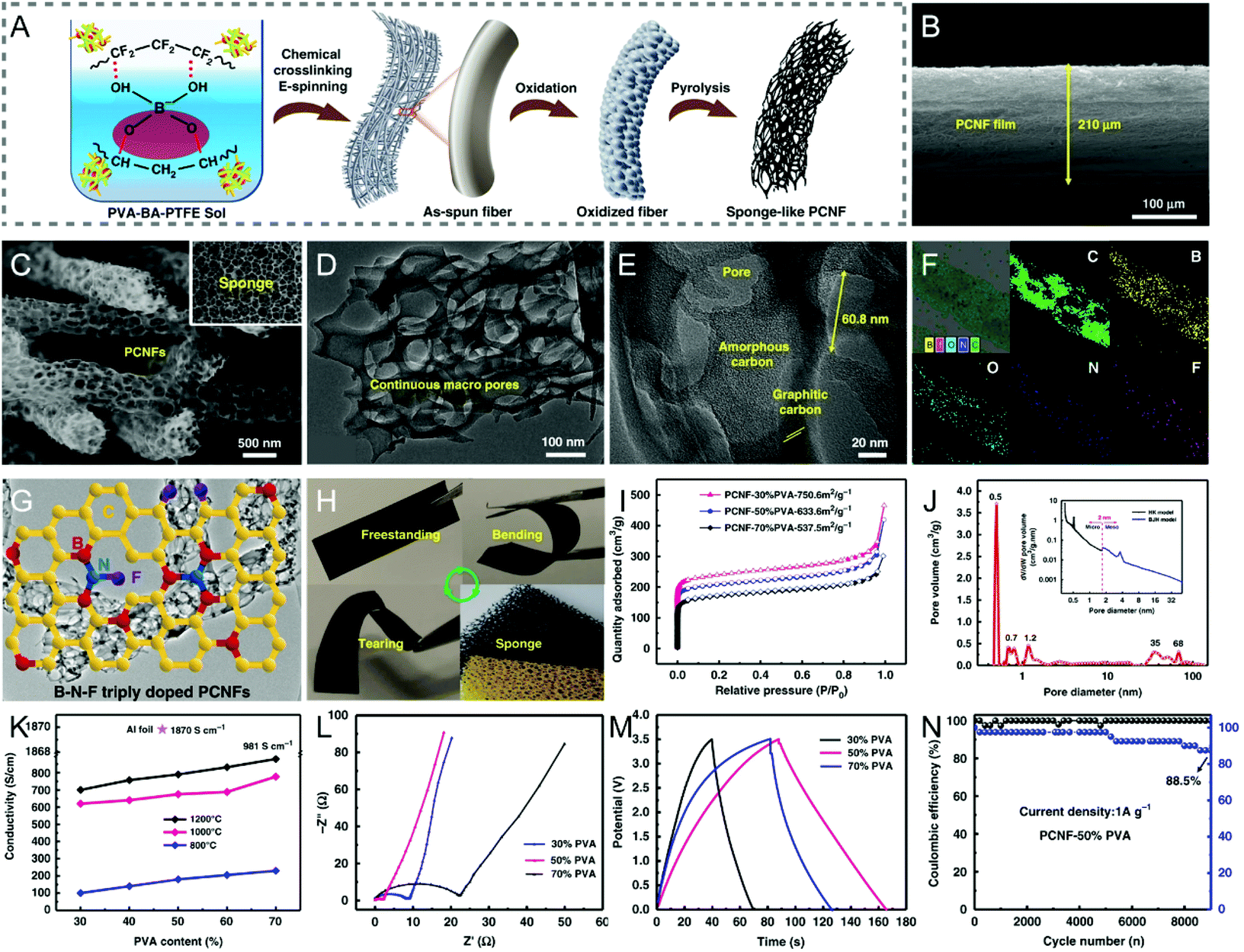 | ||
| Fig. 9 (A) Schematic of the fabrication of B/F/N co-doped sponge-like PCNFs by chemical crosslinking electrospinning and pyrolysis. SEM images of (B) the cross section of the triply doped PCNF film and (C) the PCNFs with continuous macropores at high magnification. (D and E) TEM images of a single PCNF. (F) Elemental mappings of PCNFs. (G) The proposed chemical model of the triply doped PCNFs. (H) Mechanical robustness of the PCNF membranes. (I) N2 adsorption–desorption isotherms and (J) PSD curves. (K) Conductivity of the PCNFs prepared with different PVA contents at various pyrolysis temperatures. (L) Nyquist plots, (M) GCD curves, and (N) cycling performance of the symmetric supercapacitor. Reproduced with permission from ref. 223. Copyright 2019, Springer Nature. | ||
There is no doubt that doping various heteroatoms into electrospun CNFs can strongly impact their electrochemical activity. These heteroatoms can also affect other key parameters that have been discussed above, such as electrical conductivity, surface area and degree of graphitization. For example, N-doped carbon is known for better conductivity than that of un-doped carbon, depending on the type and concentration of N-containing groups. The heteroatoms in CNFs will change both the electronic and chemical structure, as well as the surface termination groups.
5. Mechanical robustness and flexibility
Mechanical robustness and flexibility are among the essential key parameters, especially for those energy-related applications in bendable, foldable, and wearable electronics. Similar to the commercial carbon fibers, the tensile modulus of electrospun CNFs is largely determined by the degree of graphitization, the size and configuration of graphitic domains, crystallite orientation, and porosity. Therefore, those discussions presented above on processing controls in an attempt to improve the conductivity, pore structure and even heteroatom doping can be linked to the mechanical properties of electrospun CNFs, either directly or indirectly. To date, numerous efforts have been devoted to correlating the modulus and strength to the type and level of pores in fibers, with multiple relationships being drawn. Some considered that the mechanical strength of porous carbon materials was inversely dependent on the overall porosity level, and some felt that it was influenced by the total pore volume and the biggest pore size.122,226,227 Song et al. and Ding et al. also agreed that micropores or mesopores in the carbon structures do not benefit the mechanical robustness of CNFs.228,229 It has been reported that macroporous CNFs could steadily recover their original shapes after being folded, which was presumably due to the fact that the macropores effectively dissipated stresses when the CNFs were in the bending deformation.228The electrospun CNFs with an appropriate design have indeed shown a certain mechanical stability in flexible devices under different types of deformations.29,74,90,156,223 However, there remains a rather long way to go before they are put into practical applications in large scales. Several representative processing strategies to significantly boost the mechanical performance of CNFs have been proposed, including the orientation of electrospun polymer nanofibers, regulation of pre-oxidation and carbonization temperatures, and addition of CNTs, graphene or other crossing-linking agents into CNFs. Aligned polymer nanofibers can be obtained by the specific collecting units, such as a rapidly rotating metal mandrel (cylinder, disc, etc.), flowing water bath, and auxiliary magnetic or electric field.230–233 In order to further promote the orientation of polymer chains, hot-/dry-drawing treatments can be conducted prior to the pre-oxidative stabilization process.234–236 Highly oriented chain-induced graphitic alignment enhanced the average strength and modulus of the hot-drawn PAN-derived CNFs to a large extent, and the strength carbonized at 1100 °C was as high as 5.4 GPa (the tensile strength of the commercially available Toray T1000® carbon fibers is ∼7 GPa).236,237
To strengthen electrospun CNFs, during the stabilization of precursor fibers, the heating rate is often kept at a low value, e.g., 3 °C min−1 or even lower, to avoid the explosive release of massive heat caused by the complicated chemical reactions, otherwise, the fiber orientations might be reduced, owing to the unwanted fusing of polymers.27 The pre-oxidation temperature not only affects the structure of the stabilized PAN nanofibers (see section 2), but also plays an important role in tailoring their mechanical properties,37,238 so the robustness and flexibility of the resulting CNFs are expected to change accordingly. The same applies to the pre-oxidative stabilization time, which must be appropriate, as a long pre-oxidative time may result in the formation of undesirable defects in CNFs, and too short a stabilization time will lead to the lack of thermally stable ladder structures, decreasing the crystallinity of CNFs, and all of these have great impact on the mechanical strength of the CNFs.239 Increasing the final carbonization temperature has been demonstrated to boost both the electrical conductivity and the mechanical robustness of electrospun CNFs by expanding the graphitic structures.234 For example, when the temperature was increased from 1000 to 2200 °C, the tensile strength and the Young's modulus of electrospun CNFs were improved by ∼67% and ∼45% to (542 ± 45) MPa and (58 ± 6) GPa, respectively.234
A simple addition of CNTs or graphene nanoribbons to the spinning solution can effectively enhance the mechanical flexibility of the resulting CNFs by templated graphitization, where CNTs or graphene nanoribbons act as the templates to facilitate the transformation of local polymers to highly-ordered graphitic carbons.240–243 When the size of graphene is reduced down to a scale of quantum dots (QDs), the reinforcing mechanism is mainly based on the cross-linking effect.244,245 For example, the KOH-activated graphene QD-reinforced CNFs (AGRCNFs) with a well-developed porous structure, ultrahigh SSA (2032 m2 g−1), and favorable conductivity present a tensile strength of ∼3 MPa, which is 2.5 times that of CNFs (1.2 MPa), arising from the strong cross-linking between PAN chains and graphene QDs that are rich in oxygen-containing functional groups (Fig. 10A and C–E).245 As exhibited in Fig. 10B, the AGRCNF membrane can readily recover to its initial state after being grasped, folded, and twisted multiple times. Interestingly, the folded AGRCNF membrane (thickness: 700 μm) can lift a weight of 200 g, indicating its remarkable mechanical strength and flexibility. The as-prepared binder-free electrode shows an excellent specific capacitance of 358.4 F g−1 at the current density of 1 A g−1 and a superior rate capability with 76% capacitance retention at 100 A g−1 (Fig. 10F–H). Electrospun nanofibrous membranes are usually nonwoven assemblies, composed of randomly oriented nanofibers overlapping each other with weak interactions. The introduction of certain cross-linking agents would increase the joints between fibers, thereby forming a dense and robust 3D network. Other cross-linking agents, such as Cu(NO3)2 can coordinate with PVP to result in the fabrication of highly conductive flexible CNFs.246
 | ||
| Fig. 10 (A) Schematic illustration of the preparation process of AGRCNFs. (B) Mechanical properties of the AGRCNF films. (C) N2 adsorption–desorption isotherms and (D) PSD curves. (E) Tensile stress and conductivity of the AGRCNFs. (F–H) Electrochemical performance tested in a three-electrode system: (F) CV curves, (G) GCD profiles, and (H) rate capability. Reproduced with permission from ref. 245. Copyright 2020, American Chemical Society. | ||
6. Summary and challenges
In summary, we have looked into the on-going approaches to address some of the key issues faced by electrospun CNFs for their energy applications, with reference to supercapacitors (as listed in Table S1†). To date, tremendous progress has indeed been made with the strategies that aim to significantly improve their electrochemical performance, including the key parameters such as electrical conductivity, specific surface area, electrochemical activity, and mechanical flexibility and robustness, by approaches, e.g., catalytic graphitization, template and etching methods for pore engineering, heteroatom doping with single, dual and ternary elements, introduction of CNTs, graphene and other conductive carbon forms or cross-linking agents, control in fiber orientations, etc. For rationally designed CNFs, the electrical conductivity could reach up to ∼1000 S cm−1, and the surface area is as high as ∼2400 m2 g−1. When applied as the electrode in supercapacitors, they can achieve a specific capacitance of over 300 F g−1, which is at least comparable to those of other competing carbon-based materials, such as graphene. In addition, electrospun CNFs have been widely used as substrate supports for many other active materials, due to their excellent electrical conductivity, high surface area, good stability and mechanical robustness, giving rise to much improved electrochemical performance. Flexible devices are among the currently on-going pursuits for both energy storage and conversion, where electrospun CNFs present favorable opportunities, owing to their 1D morphology and outstanding flexibility, on top of the above-mentioned electrical and electrochemical behaviors. In the present work, we have described their energy applications by reference to supercapacitors. The same discussions can be extended to other energy devices, such as rechargeable batteries and hybrid types.There is no doubt that these key issues faced by electrospun CNFs and those newly emerging ones will be further addressed in the coming few years, especially for their application in the wide spectrum of energy storage and conversion. There also remain several challenges and opportunities:
(a) Trade-off among the key performance parameters:
Good electrical conductivity, large specific surface area, high electrochemical activity, and strong mechanical robustness are among important parameters for CNFs as freestanding electrodes toward high-performance supercapacitors. However, it is of challenge to integrate these functionalities to full strength together in the same CNFs, since there exist one or more trade-offs among them. In detail, micropores can increase the specific surface area and promote the capacitance at low current densities; mesopores facilitate a rapid ion transfer and improve the rate capability. However, the introduction of micropores and/or mesopores in the carbon structures will apparently not contribute to the enhancement of mechanical strength, and may even have an adverse effect on the flexibility of CNFs.228,229 On the other hand, certain macropores in CNFs can effectively buffer the stress caused by the bending deformation and/or volume expansion, but these materials usually have large volumes, which is not conducive to the volume specific capacity. Besides, when the continuous conjugated network of the carbon skeleton in CNFs is interrupted by the highly-developed pores, there can be a serious decrease in conductivity.
(b) A complicated story with mix-ups:
In an attempt to improve the electrochemical performance of elctrospun CNFs, a combination of multiple activation strategies has often been employed, where there are dual/multiple mechanisms to increase the overall performance. Even for a single activation process, for example, by either physical or chemical activation, it can bring in multiple structure and functionality changes. In addition, as introduced in sections 2 and 3, some metal species produced by the decomposition of the corresponding metal salts can catalyze the graphitization of CNFs during thermal treatments, and at the same time, they also act as inorganic templates for pore architectures. It is thus difficult to generalize a quantitative structure–activity relationship between the electrochemical performance and the variables, such as conductivity, level of porosity, and heteroatom content, owing to the inability to accurately control a single variable with other parameters unchanged. This does not help the rational design of CNFs with an optimum structure and thus properties.
(c) Still lack of understanding on some key basics:
Although electrospun CNFs have been extensively investigated over the past more than one decade, there is still a considerable lack of understanding on some of the key fundamental aspects. Taking the heteroatom doping as an example, especially dual doping, ternary doping or multiple doping, previous efforts were mainly focused on proving the activation concepts, approaches, and overall effects for CNFs. There is an apparent lack of basic understanding on the interactions or synergistic effects among different doping elements in most cases. Nitrogen-doped carbon-based materials have been extensively investigated, both experimentally and theoretically, where the doping configuration and concentration in the carbon lattice notably influence the electrochemical behavior. Nevertheless, the local electronic structure and surface chemistry of the host carbon doped by other heteroatoms, such as fluorine, phosphorus, and sulfur, remain unclear and disputable, which would need theoretical simulation to clarify how to construct the optimal doping configuration experimentally. Concerning the structure-performance relationship of CNFs, there is still a considerable lack of understanding on some key basic governing principles.
(d) Different functions:
The specific capacitance and energy density of carbon-based materials are largely limited by the low theoretical capacity, which is also applicable to electrospun CNFs. Instead by themselves alone, CNFs shall be further expanded as conductive substrates to support other electroactive materials, e.g., metal oxides/hydroxides, non-oxides, and conducting polymers, to construct high-performance flexible wearable devices. In this connection, there will be challenging issues on the proper and optimum integration, especially at the interfaces.
(e) High cost and low yield limiting large-scale applications:
In research, a lot of “complicated stories” have been created with CNFs in an attempt to raise one or two of their performance parameters, and the high cost arising makes them impossible for industry to adopt. Mass production of CNFs at low cost via electrospinning is a key technical issue that needs to be addressed for large-volume applications. The extensively-used PAN, which accounts for ∼90% of the total market for CNF precursors, is relatively expensive. In addition, it is rather troublesome to recover some of the toxic solvents, such as DMF, which adds on extra costs. Ideally, there shall be cheap, high-quality polymer precursors and low cost, industry-scale electrospinning equipment to be developed, which would allow for the mass production of CNFs, in response to the expected large demand for various energy applications. At the time being, unfortunately, it appears to be a long distance off, although great progress has been made with electrospun CNFs, as has been reviewed in the present study, and it has been moving in the right direction.
Conflicts of interest
There are no conflicts to declare.Acknowledgements
This work was supported by the research grants from the Natural Science Foundation of Shandong Province, China (ZR2019BEM001), the China Postdoctoral Science Foundation (2018M630745), and the National Natural Science Foundation of China (51673103). JW acknowledges the support of MOE (Tier 1 R284-000-193-114 and Tier 2 R284-000-204-112), research conducted at the National University of Singapore.References
- Q. Wang, J. Yan and Z. J. Fan, Energy Environ. Sci., 2016, 9, 729–762 RSC.
- W. Zhang, S. Y. Zhu, R. Luque, S. Han, L. Z. Hua and G. B. Xu, Chem. Soc. Rev., 2016, 45, 715–752 RSC.
- H. S. Hou, X. Q. Qiu, W. F. Wei, Y. Zhang and X. B. Ji, Adv. Energy Mater., 2017, 7, 1602898 CrossRef.
- X. F. Lu, C. Wang, F. Favier and N. Pinna, Adv. Energy Mater., 2017, 7, 1601301 CrossRef.
- K. X. Wang, W. H. Zhang, R. Phelan, M. A. Morris and J. D. Holmes, J. Am. Chem. Soc., 2007, 129, 13388–13389 CrossRef CAS PubMed.
- H. W. Liang, Q. F. Guan, L. F. Chen, Z. Zhu, W. J. Zhang and S. H. Yu, Angew. Chem., Int. Ed., 2012, 51, 5101–5105 CrossRef CAS PubMed.
- E. Kang, G. Jeon and J. K. Kim, Chem. Commun., 2013, 49, 6406–6408 RSC.
- Z. G. Zhu, Y. Xu, B. Y. Qi, G. F. Zeng, P. Wu, G. J. Liu, W. Wang, F. Y. Cui and Y. H. Sun, Environ. Sci.: Nano, 2017, 4, 302–306 RSC.
- X. F. Lu, M. X. Li, H. Y. Wang and C. Wang, Inorg. Chem. Front., 2019, 6, 3012–3040 RSC.
- Z. G. Zhu, C. H. Ji, L. L. Zhong, S. Liu, F. Y. Cui, H. L. Sun and W. Wang, J. Mater. Chem. A, 2017, 5, 18071–18080 RSC.
- M. Inagaki, Y. Yang and F. Y. Kang, Adv. Mater., 2012, 24, 2547–2566 CrossRef CAS PubMed.
- W. Li, R. Y. Fang, Y. Xia, W. K. Zhang, X. L. Wang, X. H. Xia and J. P. Tu, Batteries Supercaps, 2019, 2, 9–36 CrossRef CAS.
- B. Zhang, F. Y. Kang, J. M. Tarascon and J. K. Kim, Prog. Mater. Sci., 2016, 76, 319–380 CrossRef CAS.
- Z. G. Zhu, L. L. Zhong, Z. Q. Zhang, H. R. Li, W. X. Shi, F. Y. Cui and W. Wang, J. Mater. Chem. A, 2017, 5, 25266–25275 RSC.
- S. K. Nataraj, K. S. Yang and T. M. Aminabhavi, Prog. Polym. Sci., 2012, 37, 487–513 CrossRef CAS.
- Y. Z. Zhang, Z. Zhang, S. Liu, G. R. Li and X. P. Gao, ACS Appl. Mater. Interfaces, 2018, 10, 8749–8757 CrossRef CAS PubMed.
- H. Khayyam, R. N. Jazar, S. Nunna, G. Golkarnarenji, K. Badii, S. M. Fakhrhoseini, S. Kumar and M. Naebe, Prog. Mater. Sci., 2020, 107, 100575 CrossRef.
- L. T. Dong, G. W. Wang, X. F. Li, D. B. Xiong, B. Yan, B. X. Chen, D. J. Li and Y. H. Cui, RSC Adv., 2016, 6, 4193–4199 RSC.
- P. Q. Wang, D. Zhang, F. Y. Ma, Y. Ou, Q. N. Chen, S. H. Xie and J. Y. Li, Nanoscale, 2012, 4, 7199–7204 RSC.
- Y. Liu, X. D. Yan, Y. H. Yu and X. P. Yang, ACS Sustainable Chem. Eng., 2016, 4, 2951–2959 CrossRef CAS.
- B. E. Conway, Electrochemical supercapacitors: scientific fundamentals and technological applications, Springer Science & Business Media, New York, 1999 Search PubMed.
- V. Augustyn, P. Simon and B. Dunn, Energy Environ. Sci., 2014, 7, 1597–1614 RSC.
- G. P. Wang, L. Zhang and J. J. Zhang, Chem. Soc. Rev., 2012, 41, 797–828 RSC.
- J. M. Jiang, Y. D. Zhang, P. Nie, G. Y. Xu, M. Y. Shi, J. Wang, Y. T. Wu, R. R. Fu, H. Dou and X. G. Zhang, Adv. Sustainable Syst., 2018, 2, 1700110 CrossRef.
- Z. Wu, L. Li, J. M. Yan and X. B. Zhang, Adv. Sci., 2017, 4, 1600382 CrossRef PubMed.
- C. C. Liu, X. J. Yan, F. Hu, G. H. Gao, G. M. Wu and X. W. Yang, Adv. Mater., 2018, 30, 1705713 CrossRef PubMed.
- X. W. Mao, T. A. Hatton and G. C. Rutledge, Curr. Org. Chem., 2013, 17, 1390–1401 CrossRef CAS.
- C. Kim, K. S. Yang, M. Kojima, K. Yoshida, Y. J. Kim, Y. A. Kim and M. Endo, Adv. Funct. Mater., 2006, 16, 2393–2397 CrossRef CAS.
- Y. Liu, J. Y. Zhou, L. L. Chen, P. Zhang, W. B. Fu, H. Zhao, Y. F. Ma, X. J. Pan, Z. X. Zhang, W. H. Han and E. Q. Xie, ACS Appl. Mater. Interfaces, 2015, 7, 23515–23520 CrossRef CAS PubMed.
- S. L. Zhao, D. W. Wang, R. Amal and L. M. Dai, Adv. Mater., 2019, 31, 1801526 CrossRef PubMed.
- C. G. Hu and L. M. Dai, Angew. Chem., Int. Ed., 2016, 55, 11736–11758 CrossRef CAS PubMed.
- M. R. Benzigar, S. N. Talapaneni, S. Joseph, K. Ramadass, G. Singh, J. Scaranto, U. Ravon, K. Al-Bahily and A. Vinu, Chem. Soc. Rev., 2018, 47, 2680–2721 RSC.
- J. Wang, P. Nie, B. Ding, S. Y. Dong, X. D. Hao, H. Dou and X. G. Zhang, J. Mater. Chem. A, 2017, 5, 2411–2428 RSC.
- M. S. A. Rahaman, A. F. Ismail and A. Mustafa, Polym. Degrad. Stab., 2007, 92, 1421–1432 CrossRef CAS.
- S. Arbab, A. Teimoury, H. Mirbaha, D. C. Adolphe, B. Noroozi and P. Nourpanah, Polym. Degrad. Stab., 2017, 142, 198–208 CrossRef CAS.
- A. Gupta, S. R. Dhakate, P. Pal, A. Dey, P. K. Iyer and D. K. Singh, Diamond Relat. Mater., 2017, 78, 31–38 CrossRef CAS.
- Q. J. Duan, B. Wang and H. P. Wang, J. Macromol. Sci., Part B: Phys., 2012, 51, 2428–2437 CrossRef CAS.
- M. Zhang, F. L. Yan, X. Tang, Q. H. Li, T. H. Wang and G. Z. Cao, J. Mater. Chem. A, 2014, 2, 5890–5897 RSC.
- Y. T. Tan, D. S. Lin, C. Liu, W. C. Wang, L. Kang and F. Ran, J. Mater. Res., 2018, 33, 1120–1130 CrossRef CAS.
- A. Ōya and S. Ōtani, Carbon, 1979, 17, 131–137 CrossRef.
- B. Zhang, Z. L. Xu, Y. B. He, S. Abouali, M. A. Garakani, E. K. Heidari, F. Y. Kang and J. K. Kim, Nano Energy, 2014, 4, 88–96 CrossRef CAS.
- M. Li, L. B. Liu, Y. P. Xiong, X. T. Liu, A. Nsabimana, X. J. Bo and L. P. Guo, Sens. Actuators, B, 2015, 207, 614–622 CrossRef CAS.
- L. W. Ji, O. Toprakci, M. Alcoutlabi, Y. F. Yao, Y. Li, S. Zhang, B. K. Guo, Z. Lin and X. W. Zhang, ACS Appl. Mater. Interfaces, 2012, 4, 2672–2679 CrossRef CAS PubMed.
- L. J. Zhang, Y. Z. Jiang, L. W. Wang, C. Zhang and S. X. Liu, Electrochim. Acta, 2016, 196, 189–196 CrossRef CAS.
- S. Abouali, M. A. Garakani, B. Zhang, H. Luo, Z. L. Xu, J. Q. Huang, J. Q. Huang and J. K. Kim, J. Mater. Chem. A, 2014, 2, 16939–16944 RSC.
- Y. J. Lee, Y. Uchiyama and L. R. Radovic, Carbon, 2004, 42, 2233–2244 CrossRef CAS.
- J. S. Yeo, S. M. Jang, J. Miyawaki, B. An, I. Mochida, C. K. Rhee and S. H. Yoon, Nanotechnology, 2012, 23, 315602 CrossRef PubMed.
- Z. P. Zhou and X. F. Wu, J. Power Sources, 2013, 222, 410–416 CrossRef CAS.
- Q. Dong, G. Wang, H. Hu, J. Yang, B. Q. Qian, Z. Ling and J. S. Qiu, J. Power Sources, 2013, 243, 350–353 CrossRef CAS.
- B. H. Kim and K. S. Yang, J. Ind. Eng. Chem., 2014, 20, 3474–3479 CrossRef CAS.
- A. Moayeri and A. Ajji, J. Nanosci. Nanotechnol., 2017, 17, 1820–1829 CrossRef CAS.
- W. K. Chee, H. N. Lim, Z. Zainal, I. Harrison, Y. Andou, N. M. Huang, M. Altarawneh and Z. T. Jiang, Mater. Lett., 2017, 199, 200–203 CrossRef CAS.
- W. K. Chee, H. N. Lim, Y. Andou, Z. Zainal, A. A. B. Hamra, I. Harrison, M. Altarawneh, Z. T. Jiang and N. M. Huang, J. Energy Chem., 2017, 26, 790–798 CrossRef.
- X. D. Tian, X. Li, T. Yang, K. Wang, H. B. Wang, Y. Song, Z. J. Liu, Q. G. Guo and C. M. Chen, Electrochim. Acta, 2017, 247, 1060–1071 CrossRef CAS.
- Y. K. Kim, S. I. Cha, S. H. Hong and Y. J. Jeong, J. Mater. Chem., 2012, 22, 20554–20560 RSC.
- L. B. Deng, R. J. Young, I. A. Kinloch, A. M. Abdelkader, S. M. Holmes, D. A. De Haro-Del Rio and S. J. Eichhorn, ACS Appl. Mater. Interfaces, 2013, 5, 9983–9990 CrossRef CAS PubMed.
- W. M. Chang, C. C. Wang and C. Y. Chen, Electrochim. Acta, 2015, 186, 530–541 CrossRef CAS.
- H. C. Hsu, C. H. Wang, Y. C. Chang, J. H. Hu, B. Y. Yao and C. Y. Lin, J. Phys. Chem. Solids, 2015, 85, 62–68 CrossRef CAS.
- C. Ma, L. Q. Wu, L. Zheng, R. H. Gan, Q. C. Fan, Y. Song and J. L. Shi, J. Nanopart. Res., 2019, 21, 33 CrossRef.
- S. J. He, L. L. Chen, C. C. Xie, H. Hu, S. L. Chen, M. Hanif and H. Q. Hou, J. Power Sources, 2013, 243, 880–886 CrossRef CAS.
- Q. H. Guo, X. P. Zhou, X. Y. Li, S. L. Chen, A. Seema, A. Greiner and H. Q. Hou, J. Mater. Chem., 2009, 19, 2810–2816 RSC.
- C. Ma, X. Wang, Y. Ma, J. Sheng, Y. J. Li, S. Z. Li and J. L. Shi, Mater. Lett., 2015, 145, 197–200 CrossRef CAS.
- G. M. Luo, Y. Z. Wang, L. X. Gao, D. Q. Zhang and T. Lin, Electrochim. Acta, 2018, 260, 656–663 CrossRef CAS.
- Y. P. Huang, F. L. Lai, L. S. Zhang, H. Y. Lu, Y. E. Miao and T. X. Liu, Sci. Rep., 2016, 6, 31541 CrossRef CAS PubMed.
- Y. C. Qiu, G. Z. Li, Y. Hou, Z. H. Pan, H. F. Li, W. F. Li, M. N. Liu, F. M. Ye, X. W. Yang and Y. G. Zhang, Chem. Mater., 2015, 27, 1194–1200 CrossRef CAS.
- Q. Li, L. B. Deng, J. K. Kim, Y. Q. Zhu, S. M. Holmes, M. Perez-Page and S. J. Eichhorn, J. Electrochem. Soc., 2017, 164, A3220–A3228 CrossRef CAS.
- Q. X. Xie, S. W. Zhou, S. H. Wu, Y. F. Zhang and P. Zhao, Appl. Surf. Sci., 2017, 407, 36–43 CrossRef CAS.
- T. Y. Kou, B. Yao, T. Y. Liu and Y. Li, J. Mater. Chem. A, 2017, 5, 17151–17173 RSC.
- T. Y. Liu, F. Zhang, Y. Song and Y. Li, J. Mater. Chem. A, 2017, 5, 17705–17733 RSC.
- D. Lee, J. Y. Jung, M. J. Jung and Y. S. Lee, Chem. Eng. J., 2015, 263, 62–70 CrossRef CAS.
- S. Ghosh, W. D. Yong, E. M. Jin, S. R. Polaki, S. M. Jeong and H. Jun, Korean J. Chem. Eng., 2019, 36, 312–320 CrossRef CAS.
- L. Fan, L. Yang, X. Y. Ni, J. Han, R. Guo and C. F. (J.) Zhang, Carbon, 2016, 107, 629–637 CrossRef CAS.
- A. Gopalakrishnan, P. Sahatiya and S. Badhulika, ChemElectroChem, 2018, 5, 531–539 CrossRef CAS.
- L. Wang, G. H. Zhang, X. J. Zhang, H. M. Shi, W. Zeng, H. Zhang, Q. Liu, C. C. Li, Q. H. Liu and H. G. Duan, J. Mater. Chem. A, 2017, 5, 14801–14810 RSC.
- W. H. Xie, X. Y. Jiang, T. F. Qin, H. Yang, D. Q. Liu and D. Y. He, Electrochim. Acta, 2017, 258, 1064–1071 CrossRef CAS.
- R. Singhal and V. Kalra, J. Mater. Chem. A, 2015, 3, 377–385 RSC.
- C. Z. Zhan, Q. Xu, X. L. Yu, Q. H. Liang, Y. Bai, Z. H. Huang and F. Y. Kang, RSC Adv., 2016, 6, 41473–41476 RSC.
- H. Liu, W. G. Song and A. H. Xing, RSC Adv., 2019, 9, 33539–33548 RSC.
- H. Liu, C. Y. Cao, F. F. Wei, Y. Jiang, Y. B. Sun, P. P. Huang and W. G. Song, J. Phys. Chem. C, 2013, 117, 21426–21432 CrossRef CAS.
- K. K. Karthikeyan and P. Biji, Microporous Mesoporous Mater., 2016, 224, 372–383 CrossRef CAS.
- C. Ma, E. C. Cao, J. J. Li, Q. C. Fan, L. Q. Wu, Y. Song and J. L. Shi, Electrochim. Acta, 2018, 292, 364–373 CrossRef CAS.
- T. H. Le, H. Tian, J. Cheng, Z. H. Huang, F. Y. Kang and Y. Yang, Carbon, 2018, 138, 325–336 CrossRef CAS.
- C. Ma, Z. Y. Li, J. J. Li, Q. C. Fan, L. Q. Wu, J. L. Shi and Y. Song, Appl. Surf. Sci., 2018, 456, 568–576 CrossRef CAS.
- J. Tan, Y. L. Han, L. He, Y. X. Dong, X. Xu, D. N. Liu, H. W. Yan, Q. Yu, C. Y. Huang and L. Q. Mai, J. Mater. Chem. A, 2017, 5, 23620–23627 RSC.
- G. H. An and H. J. Ahn, Carbon, 2013, 65, 87–96 CrossRef CAS.
- Q. Li, W. H. Xie, D. Q. Liu, Q. Wang and D. Y. He, Electrochim. Acta, 2016, 222, 1445–1454 CrossRef CAS.
- C. Kim, B. T. N. Ngoc, K. S. Yang, M. Kojima, Y. A. Kim, Y. J. Kim, M. Endo and S. C. Yang, Adv. Mater., 2007, 19, 2341–2346 CrossRef CAS.
- C. Ma, J. N. Chen, Q. C. Fan, J. C. Guo, W. N. Liu, E. C. Cao, J. L. Shi and Y. Song, J. Mater. Sci., 2018, 53, 4527–4539 CrossRef CAS.
- Q. T. Jiang, X. Pang, S. T. Geng, Y. H. Zhao, X. M. Wang, H. Qin, B. Liu, J. Zhou and T. Zhou, Appl. Surf. Sci., 2019, 479, 128–136 CrossRef CAS.
- Y. M. Sun, R. B. Sills, X. L. Hu, Z. W. Seh, X. Xiao, H. H. Xu, W. Luo, H. Y. Jin, Y. Xin, T. Q. Li, Z. L. Zhang, J. Zhou, W. Cai, Y. H. Huang and Y. Cui, Nano Lett., 2015, 15, 3899–3906 CrossRef CAS PubMed.
- Q. Wang, Q. Cao, X. Y. Wang, B. Jing, H. Kuang and L. Zhou, J. Solid State Electrochem., 2013, 17, 2731–2739 CrossRef CAS.
- J. Wang, J. Tang, Y. L. Xu, B. Ding, Z. Chang, Y. Wang, X. D. Hao, H. Dou, J. H. Kim, X. G. Zhang and Y. Yamauchi, Nano Energy, 2016, 28, 232–240 CrossRef CAS.
- M. J. Wang, Y. N. Wu, J. Y. Shen, M. M. Zhou, F. T. Li and B. R. Zhang, RSC Adv., 2014, 4, 63162–63170 RSC.
- D. Zhou, Y. Dong, L. R. Cui, H. M. Lin and F. Y. Qu, J. Nanopart. Res., 2014, 16, 2732 CrossRef.
- J. Zeng, Q. Cao, X. Y. Wang, B. Jing, X. X. Peng and X. L. Tang, J. Solid State Electrochem., 2015, 19, 1591–1597 CrossRef CAS.
- C. Ma, J. Sheng, Y. Zhao, R. R. Wang, H. X. Zhang and J. L. Shi, J. Nanosci. Nanotechnol., 2018, 18, 699–704 CrossRef CAS.
- R. Z. Chen, Y. Hu, Z. Shen, P. Pan, X. He, K. S. Wu, X. W. Zhang and Z. L. Cheng, J. Mater. Chem. A, 2017, 5, 12914–12921 RSC.
- Y. X. Luan, G. D. Nie, X. W. Zhao, N. Qiao, X. C. Liu, H. Wang, X. N. Zhang, Y. Q. Chen and Y. Z. Long, Electrochim. Acta, 2019, 308, 121–130 CrossRef CAS.
- Y. M. Chen, Z. G. Lu, L. M. Zhou, Y. W. Mai and H. T. Huang, Energy Environ. Sci., 2012, 5, 7898–7902 RSC.
- Y. M. Chen, X. Y. Li, X. Y. Zhou, H. M. Yao, H. T. Huang, Y. W. Mai and L. M. Zhou, Energy Environ. Sci., 2014, 7, 2689–2696 RSC.
- T. Zhou, Q. T. Jiang, L. Wang, Z. P. Qiu, Y. Y. Liu, J. Zhou and B. Liu, Appl. Surf. Sci., 2018, 456, 827–834 CrossRef CAS.
- L. F. Chen, Y. Lu, L. Yu and X. W. (D.) Lou, Energy Environ. Sci., 2017, 10, 1777–1783 RSC.
- Y. B. Dou, W. J. Zhang and A. Kaiser, Adv. Sci., 2020, 7, 1902590 CrossRef CAS PubMed.
- Z. Y. Liu, D. Y. Fu, F. F. Liu, G. Y. Han, C. X. Liu, Y. Z. Chang, Y. M. Xiao, M. Y. Li and S. D. Li, Carbon, 2014, 70, 295–307 CrossRef CAS.
- C. H. Wang, C. Liu, J. S. Li, X. Y. Sun, J. Y. Shen, W. Q. Han and L. J. Wang, Chem. Commun., 2017, 53, 1751–1754 RSC.
- Y. C. Yao, H. L. Wu, L. Huang, X. Y. Li, L. Yu, S. Z. Zeng, X. R. Zeng, J. W. Yang and J. Z. Zou, Electrochim. Acta, 2017, 246, 606–614 CrossRef CAS.
- B. Dahal, T. Mukhiya, G. P. Ojha, A. Muthurasu, S. H. Chae, T. Kim, D. Kang and H. Y. Kim, Electrochim. Acta, 2019, 301, 209–219 CrossRef CAS.
- Y. J. Li, G. Zhu, H. L. Huang, M. Xu, T. Lu and L. K. Pan, J. Mater. Chem. A, 2019, 7, 9040–9050 RSC.
- Y. J. Gong, R. Y. Chen, H. Xu, C. Y. Yu, X. Zhao, Y. Sun, Z. Y. Hui, J. Y. Zhou, J. N. An, Z. Z. Du, G. Z. Sun and W. Huang, Nanoscale, 2019, 11, 2492–2500 RSC.
- Y. J. Li, W. Ou-Yang, X. T. Xu, M. Wang, S. J. Hou, T. Lu, Y. F. Yao and L. K. Pan, Electrochim. Acta, 2018, 271, 591–598 CrossRef CAS.
- C. H. Wang, Y. V. Kaneti, Y. Bando, J. J. Lin, C. Liu, J. S. Li and Y. Yamauchi, Mater. Horiz., 2018, 5, 394–407 RSC.
- Y. M. Chen, X. Y. Li, K. Park, W. Lu, C. Wang, W. J. Xue, F. Yang, J. Zhou, L. M. Suo, T. Q. Lin, H. T. Huang, J. Li and J. B. Goodenough, Chem, 2017, 3, 152–163 CAS.
- X. L. Li, Y. J. Zhao, Y. Bai, X. Y. Zhao, R. H. Wang, Y. C. Huang, Q. H. Liang and Z. H. Huang, Electrochim. Acta, 2017, 230, 445–453 CrossRef CAS.
- W. Na, J. Jun, J. W. Park, G. Lee and J. Jang, J. Mater. Chem. A, 2017, 5, 17379–17387 RSC.
- G. Wang, B. Q. Qian, Y. W. Wang, Q. Dong, F. Zhan and J. S. Qiu, New J. Chem., 2016, 40, 3786–3792 RSC.
- O. Pech and S. Maensiri, J. Alloys Compd., 2019, 781, 541–552 CrossRef CAS.
- P. Ramakrishnan, S. G. Park and S. Shanmugam, J. Mater. Chem. A, 2015, 3, 16242–16250 RSC.
- T. S. He, Y. R. Fu, X. L. Meng, X. D. Yu and X. L. Wang, Electrochim. Acta, 2018, 282, 97–104 CrossRef CAS.
- C. Liu, Y. T. Tan, Y. Liu, K. W. Shen, B. W. Peng, X. Q. Niu and F. Ran, J. Energy Chem., 2016, 25, 587–593 CrossRef.
- Q. Xu, X. L. Yu, Q. H. Liang, Y. Bai, Z. H. Huang and F. Y. Kang, J. Electroanal. Chem., 2015, 739, 84–88 CrossRef CAS.
- B. H. Kim, K. S. Yang and J. P. Ferraris, Electrochim. Acta, 2012, 75, 325–331 CrossRef CAS.
- Y. J. Chen, A. Amiri, J. G. Boyd and M. Naraghi, Adv. Funct. Mater., 2019, 29, 1901425 CrossRef.
- G. H. He, Y. H. Song, S. L. Chen and L. Wang, J. Mater. Sci., 2018, 53, 9721–9730 CrossRef CAS.
- N. C. Abeykoon, J. S. Bonso and J. P. Ferraris, RSC Adv., 2015, 5, 19865–19873 RSC.
- W. M. Chang, C. C. Wang and C. Y. Chen, Electrochim. Acta, 2019, 296, 268–275 CrossRef CAS.
- B. G. Hyun, H. J. Son, S. Ji, J. Jang, S. H. Hur and J. U. Park, J. Electroceram., 2017, 38, 43–50 CrossRef CAS.
- L. J. Zhang, L. L. Han, S. Liu, C. Zhang and S. X. Liu, RSC Adv., 2015, 5, 107313–107317 RSC.
- P. Ramakrishnan and S. Shanmugam, ACS Sustainable Chem. Eng., 2016, 4, 2439–2448 CrossRef CAS.
- D. S. Yang, S. Chaudhari, K. P. Rajesh and J. S. Yu, ChemCatChem, 2014, 6, 1236–1244 CAS.
- Y. W. Ju, S. H. Park, H. R. Jung and W. J. Lee, J. Electrochem. Soc., 2009, 156, A489–A494 CrossRef CAS.
- H. Wang, W. Y. Wang, H. J. Wang, X. Jin, H. T. Niu, H. X. Wang, H. Zhou and T. Lin, ACS Appl. Energy Mater., 2018, 1, 431–439 CrossRef CAS.
- H. I. Lee and S. J. Park, Carbon Lett., 2017, 23, 79–83 Search PubMed.
- K. B. Huang, M. Li, Z. H. Chen, Y. Y. Yao and X. W. Yang, Electrochim. Acta, 2015, 158, 306–313 CrossRef CAS.
- B. H. Kim, K. S. Yang, Y. A. Kim, Y. J. Kim, B. An and K. Oshida, J. Power Sources, 2011, 196, 10496–10501 CrossRef CAS.
- A. Choudhury, J. H. Kim, S. S. Mahapatra, K. S. Yang and D. J. Yang, ACS Sustainable Chem. Eng., 2017, 5, 2109–2118 CrossRef CAS.
- W. H. Li, L. C. Zeng, Z. Z. Yang, L. Gu, J. Q. Wang, X. W. Liu, J. X. Cheng and Y. Yu, Nanoscale, 2014, 6, 693–698 RSC.
- D. W. Lawrence, C. Tran, A. T. Mallajoysula, S. K. Doorn, A. Mohite, G. Gupta and V. Kalra, J. Mater. Chem. A, 2016, 4, 160–166 RSC.
- S. K. Simotwo, P. R. Chinnam, S. L. Wunder and V. Kalra, ACS Appl. Mater. Interfaces, 2017, 9, 33749–33757 CrossRef CAS PubMed.
- T. H. Le, Y. Yang, Z. H. Huang and F. Y. Kang, J. Power Sources, 2015, 278, 683–692 CrossRef CAS.
- J. Zeng, Q. Cao, B. Jing and X. X. Peng, RSC Adv., 2016, 6, 15320–15326 RSC.
- W. J. Dong, Z. Wang, Q. Zhang, M. Ravi, M. M. Yu, Y. T. Tan, Y. Liu, L. B. Kong, L. Kang and F. Ran, J. Power Sources, 2019, 419, 137–147 CrossRef CAS.
- Y. Zeng, X. Y. Li, S. H. Jiang, S. J. He, H. Fang and H. Q. Hou, Mater. Lett., 2015, 161, 587–590 CrossRef CAS.
- J. Yan, J. H. Choi and Y. G. Jeong, Mater. Des., 2018, 139, 72–80 CrossRef CAS.
- X. Wang, W. Zhang, M. Z. Chen and X. Y. Zhou, Polymers, 2018, 10, 1306 CrossRef PubMed.
- C. Ma, Y. Song, J. L. Shi, D. Q. Zhang, X. L. Zhai, M. Zhong, Q. G. Guo and L. Liu, Carbon, 2013, 51, 290–300 CrossRef CAS.
- C. L. Lai, Z. P. Zhou, L. F. Zhang, X. X. Wang, Q. X. Zhou, Y. Zhao, Y. C. Wang, X. F. Wu, Z. T. Zhu and H. Fong, J. Power Sources, 2014, 247, 134–141 CrossRef CAS.
- M. X. Guo, J. X. Guo, D. Z. Jia, H. Y. Zhao, Z. P. Sun, X. L. Song and Y. H. Li, J. Mater. Chem. A, 2015, 3, 21178–21184 RSC.
- Shilpa and A. Sharma, RSC Adv., 2016, 6, 78528–78537 RSC.
- K. H. Jung and J. P. Ferraris, Nanotechnology, 2016, 27, 425708 CrossRef PubMed.
- Z. Q. Shi, G. Q. Jin, J. Wang and J. Zhang, J. Electroanal. Chem., 2017, 795, 26–31 CrossRef CAS.
- H. Wang, W. Y. Wang, H. J. Wang, Y. R. Li, X. Jin, H. T. Niu, H. X. Wang, H. Zhou and T. Lin, Adv. Mater. Interfaces, 2019, 6, 1801900 CrossRef.
- T. H. Le, Y. Yang, L. Yu, T. J. Gao, Z. H. Huang and F. Y. Kang, J. Appl. Polym. Sci., 2016, 133, 43397 CrossRef.
- Y. L. Cheng, L. Huang, X. Xiao, B. Yao, Z. M. Hu, T. Q. Li, K. Liu and J. Zhou, J. Power Sources, 2016, 327, 488–494 CrossRef CAS.
- J. J. Lu, Z. R. Ying, X. D. Liu and S. S. Zhao, Acta Phys.-Chim. Sin., 2015, 31, 2099–2108 CAS.
- N. C. Abeykoon, S. F. Mahmood, D. J. Yang and J. P. Ferraris, Nanotechnology, 2019, 30, 435401 CrossRef CAS.
- Y. L. Cheng, L. Huang, X. Xiao, B. Yao, L. Y. Yuan, T. Q. Li, Z. M. Hu, B. Wang, J. Wan and J. Zhou, Nano Energy, 2015, 15, 66–74 CrossRef CAS.
- T. S. He, Q. Y. Su, Z. Yildiz, K. D. Cai and Y. J. Wang, Electrochim. Acta, 2016, 222, 1120–1127 CrossRef CAS.
- C. Ma, J. Sheng, C. L. Ma, R. R. Wang, J. Q. Liu, Z. Y. Xie and J. L. Shi, Chem. Eng. J., 2016, 304, 587–593 CrossRef CAS.
- X. L. Yu, J. F. Zhao, R. T. Lv, Q. H. Liang, C. Z. Zhan, Y. Bai, Z. H. Huang, W. C. Shen and F. Y. Kang, J. Mater. Chem. A, 2015, 3, 18400–18405 RSC.
- C. H. Kim, C. M. Yang, Y. A. Kim and K. S. Yang, Appl. Surf. Sci., 2019, 497, 143693 CrossRef.
- H. M. Lee, H. G. Kim, K. H. An and B. J. Kim, Carbon Lett., 2014, 15, 71–76 CrossRef.
- N. C. Abeykoon, V. Garcia, R. A. Jayawickramage, W. Perera, J. Cure, Y. J. Chabal, K. J. Balkus and J. P. Ferraris, RSC Adv., 2017, 7, 20947–20959 RSC.
- Y. T. He, L. X. Wang and D. Z. Jia, Electrochim. Acta, 2016, 194, 239–245 CrossRef CAS.
- R. A. P. Jayawickramage, K. J. Balkus Jr. and J. P. Ferraris, Nanotechnology, 2019, 30, 355402 CrossRef CAS PubMed.
- J. Cai, H. T. Niu, H. X. Wang, H. Shao, J. Fang, J. R. He, H. G. Xiong, C. J. Ma and T. Lin, J. Power Sources, 2016, 324, 302–308 CrossRef CAS.
- Y. T. He, L. X. Wang, D. Z. Jia and H. Y. Zhao, Chem. J. Chin. Univ., 2015, 36, 157–164 CAS.
- M. Kim, Y. Kim, K. M. Lee, S. Y. Jeong, E. Lee, S. H. Baeck and S. E. Shim, Carbon, 2016, 99, 607–618 CrossRef CAS.
- C. Kim and K. S. Yang, Appl. Phys. Lett., 2003, 83, 1216–1218 CrossRef CAS.
- C. Kim, J. Power Sources, 2005, 142, 382–388 CrossRef CAS.
- C. Kim, S. H. Park, W. J. Lee and K. S. Yang, Electrochim. Acta, 2004, 50, 877–881 CrossRef CAS.
- C. Kim, J. S. Kim, S. J. Kim, W. J. Lee and K. S. Yang, J. Electrochem. Soc., 2004, 151, A769–A773 CrossRef CAS.
- C. Kim, Y. O. Choi, W. J. Lee and K. S. Yang, Electrochim. Acta, 2004, 50, 883–887 CrossRef CAS.
- J. S. Bonso, G. D. Kalaw and J. P. Ferraris, J. Mater. Chem. A, 2014, 2, 418–424 RSC.
- H. Y. Zhao, L. X. Wang, D. Z. Jia, W. Xia, J. Li and Z. P. Guo, J. Mater. Chem. A, 2014, 2, 9338–9344 RSC.
- S. J. Zheng, T. Zhu, Y. E. Chen, C. Lin, Y. G. Chen and H. B. Guo, J. Nanopart. Res., 2014, 16, 2649 CrossRef.
- J. C. Wang and S. Kaskel, J. Mater. Chem., 2012, 22, 23710–23725 RSC.
- Y. J. Heo, H. I. Lee, J. W. Lee, M. Park, K. Y. Rhee and S. J. Park, Composites, Part B, 2019, 161, 10–17 CrossRef CAS.
- F. L. Lai, Y. P. Huang, L. Z. Zuo, H. H. Gu, Y. E. Miao and T. X. Liu, J. Mater. Chem. A, 2016, 4, 15861–15869 RSC.
- C. Ma, Y. J. Li, J. L. Shi, Y. Song and L. Liu, Chem. Eng. J., 2014, 249, 216–225 CrossRef CAS.
- W. Yang, Z. R. Shi, H. Guo, J. Guo, X. Lei and L. G. Yue, Int. J. Electrochem. Sci., 2017, 12, 5587–5597 CrossRef CAS.
- M. J. Zhi, S. H. Liu, Z. L. Hong and N. Q. Wu, RSC Adv., 2014, 4, 43619–43623 RSC.
- Q. C. Fan, C. Ma, L. Q. Wu, C. B. Wei, H. H. Wang, Y. Song and J. L. Shi, RSC Adv., 2019, 9, 6419–6428 RSC.
- J. J. Duan, S. Chen, M. Jaroniec and S. Z. Qiao, ACS Catal., 2015, 5, 5207–5234 CrossRef CAS.
- X. Y. Wang, Q. D. Zhao, B. Yang, Z. J. Li, Z. Bo, K. H. Lam, N. M. Adli, L. C. Lei, Z. H. Wen, G. Wu and Y. Hou, J. Mater. Chem. A, 2019, 7, 25191–25202 RSC.
- Y. Nie and Z. D. Wei, ChemCatChem, 2019, 11, 5885–5897 CrossRef CAS.
- Q. W. Lin, J. Zhang, W. Lv, J. B. Ma, Y. B. He, F. Y. Kang and Q. H. Yang, Small, 2020, 16, 1902603 CrossRef CAS PubMed.
- C. G. Hu and L. M. Dai, Adv. Mater., 2019, 31, 1804672 CrossRef PubMed.
- G. D. Nie, Y. Zhu, D. Tian and C. Wang, Chem. J. Chin. Univ., 2018, 39, 1349–1363 CAS.
- Y. F. Chen, Q. Liu and J. C. Wang, J. Mater. Chem. A, 2016, 4, 5553–5560 RSC.
- G. S. Park, J. S. Lee, S. T. Kim, S. Park and J. Cho, J. Power Sources, 2013, 243, 267–273 CrossRef CAS.
- C. Liu, N. Xiao, Y. W. Wang, Y. Zhou, G. Wang, H. Q. Li, Y. Q. Ji and J. S. Qiu, Carbon, 2018, 139, 716–724 CrossRef CAS.
- Q. Jiang, M. Z. Liu, C. L. Shao, X. W. Li, H. Y. Liu, X. H. Li and Y. C. Liu, Electrochim. Acta, 2020, 330, 135212 CrossRef CAS.
- Q. H. Liang, L. Ye, Q. Xu, Z. H. Huang, F. Y. Kang and Q. H. Yang, Carbon, 2015, 94, 342–348 CrossRef CAS.
- G. L. Xia, L. J. Zhang, X. W. Chen, Y. Q. Huang, D. L. Sun, F. Fang, Z. P. Guo and X. B. Yu, Energy Storage Mater., 2018, 14, 314–323 CrossRef.
- V. Kuzmenko, O. Naboka, H. Staaf, M. Haque, G. Göransson, P. Lundgren, P. Gatenholm and P. Enoksson, Mater. Chem. Phys., 2015, 160, 59–65 CrossRef CAS.
- L. C. Zeng, W. H. Li, J. X. Cheng, J. Q. Wang, X. W. Liu and Y. Yu, RSC Adv., 2014, 4, 16920–16927 RSC.
- J. Cai, H. T. Niu, Z. Y. Li, Y. Du, P. Cizek, Z. L. Xie, H. G. Xiong and T. Lin, ACS Appl. Mater. Interfaces, 2015, 7, 14946–14953 CrossRef CAS PubMed.
- F. J. Miao, C. L. Shao, X. H. Li, K. X. Wang and Y. C. Liu, J. Mater. Chem. A, 2016, 4, 4180–4187 RSC.
- Y. E. Miao, J. J. Yan, Y. Ouyang, H. Y. Lu, F. L. Lai, Y. Wu and T. X. Liu, Appl. Surf. Sci., 2018, 443, 266–273 CrossRef CAS.
- X. W. Zhao, G. D. Nie, Y. X. Luan, X. X. Wang, S. Y. Yan and Y. Z. Long, J. Alloys Compd., 2019, 808, 151737 CrossRef CAS.
- L. Zhao, Y. J. Qiu, J. Yu, X. Y. Deng, C. L. Dai and X. D. Bai, Nanoscale, 2013, 5, 4902–4909 RSC.
- Y. J. Qiu, J. Yu, T. N. Shi, X. S. Zhou, X. D. Bai and J. Y. Huang, J. Power Sources, 2011, 196, 9862–9867 CrossRef CAS.
- X. D. Tian, N. Zhao, Y. Song, K. Wang, D. F. Xu, X. Li, Q. G. Guo and L. Liu, Electrochim. Acta, 2015, 185, 40–51 CrossRef CAS.
- J. D. Zhu, C. Chen, Y. Lu, Y. Q. Ge, H. Jiang, K. Fu and X. W. Zhang, Carbon, 2015, 94, 189–195 CrossRef CAS.
- S. X. Wang, L. P. Yang, L. P. Stubbs, X. Li and C. B. He, ACS Appl. Mater. Interfaces, 2013, 5, 12275–12282 CrossRef CAS PubMed.
- L. J. Zhang, G. L. Xia, Z. P. Guo, D. L. Sun, X. G. Li and X. B. Yu, J. Power Sources, 2016, 324, 294–301 CrossRef CAS.
- B. H. Kim, K. S. Yang and H. G. Woo, Mater. Lett., 2013, 93, 190–193 CrossRef CAS.
- G. H. An, B. R. Koo and H. J. Ahn, Phys. Chem. Chem. Phys., 2016, 18, 6587–6594 RSC.
- C. C. Lai, M. Y. Chung and C. T. Lo, Text. Res. J., 2017, 87, 2337–2348 CrossRef CAS.
- X. W. Mao, X. Q. Yang, J. Wu, W. D. Tian, G. C. Rutledge and T. A. Hatton, Chem. Mater., 2015, 27, 4574–4585 CrossRef CAS.
- R. A. Adams, J. M. Syu, Y. P. Zhao, C. T. Lo, A. Varma and V. G. Pol, ACS Appl. Mater. Interfaces, 2017, 9, 17872–17881 CrossRef CAS PubMed.
- C. C. Lai and C. T. Lo, RSC Adv., 2015, 5, 38868–38872 RSC.
- Y. Qian, S. Jiang, Y. Li, Z. Yi, J. Zhou, T. Q. Li, Y. Han, Y. S. Wang, J. Tian, N. Lin and Y. T. Qian, Adv. Energy Mater., 2019, 9, 1901676 CrossRef.
- D. S. Li, D. Y. Wang, K. Rui, Z. Y. Ma, L. Xie, J. H. Liu, Y. Zhang, R. F. Chen, Y. Yan, H. J. Lin, X. J. Xie, J. X. Zhu and W. Huang, J. Power Sources, 2018, 384, 27–33 CrossRef CAS.
- F. Wu, R. Q. Dong, Y. Bai, Y. Li, G. H. Chen, Z. H. Wang and C. Wu, ACS Appl. Mater. Interfaces, 2018, 10, 21335–21342 CrossRef CAS PubMed.
- X. D. Yan, Y. Liu, X. R. Fan, X. L. Jia, Y. H. Yu and X. P. Yang, J. Power Sources, 2014, 248, 745–751 CrossRef CAS.
- C. Liu, G. F. Shi, G. Y. Wang, P. Mishra, S. M. Jia, X. Jiang, P. Zhang, Y. C. Dong and Z. Wang, RSC Adv., 2019, 9, 6898–6906 RSC.
- W. Kiciński, M. Szala and M. Bystrzejewski, Carbon, 2014, 68, 1–32 CrossRef.
- X. Z. Sun, C. L. Wang, Y. Gong, L. Gu, Q. W. Chen and Y. Yu, Small, 2018, 14, 1802218 CrossRef PubMed.
- Z. Dai, P. G. Ren, Y. L. Jin, H. Zhang, F. Ren and Q. Zhang, J. Power Sources, 2019, 437, 226937 CrossRef CAS.
- T. L. Gong, R. Y. Qi, X. D. Liu, H. Li and Y. M. Zhang, Nano-Micro Lett., 2019, 11, 9 CrossRef CAS.
- W. M. Chen, M. Wan, Q. Liu, X. Q. Xiong, F. Q. Yu and Y. H. Huang, Small Methods, 2019, 3, 1800323 CrossRef CAS.
- J. H. Yan, K. Q. Dong, Y. Y. Zhang, X. Wang, A. A. Aboalhassan, J. Y. Yu and B. Ding, Nat. Commun., 2019, 10, 5584 CrossRef CAS PubMed.
- M. G. Wu, Y. Q. Wang, Z. X. Wei, L. Wang, M. Zhuo, J. T. Zhang, X. P. Han and J. M. Ma, J. Mater. Chem. A, 2018, 6, 10918–10925 RSC.
- L. Wang, Y. Q. Wang, M. G. Wu, Z. X. Wei, C. Y. Cui, M. L. Mao, J. T. Zhang, X. P. Han, Q. H. Liu and J. M. Ma, Small, 2018, 14, 1800737 CrossRef PubMed.
- L. Liu, Q. X. Yang and J. W. Shen, J. Nanomater., 2015, 2015, 945091 Search PubMed.
- E. A. Morris, M. C. Weisenberger, M. G. Abdallah, F. Vautard, H. Grappe, S. Ozcan, F. L. Paulauskas, C. Eberle, D. Jackson, S. J. Mecham and A. K. Naskar, Carbon, 2016, 10, 245–252 CrossRef.
- H. Liu, C. Y. Cao, F. F. Wei, P. P. Huang, Y. B. Sun, L. Jiang and W. G. Song, J. Mater. Chem. A, 2014, 2, 3557–3562 RSC.
- J. C. Zhang, F. Zhang, J. Song, L. F. Liu, Y. Si, J. Y. Yu and B. Ding, J. Mater. Chem. A, 2019, 7, 20075–20102 RSC.
- J. J. Xue, T. Wu, Y. Q. Dai and Y. N. Xia, Chem. Rev., 2019, 119, 5298–5415 CrossRef CAS PubMed.
- S. J. Peng, L. L. Li, J. K. Y. Lee, L. L. Tian, M. Srinivasan, S. Adams and S. Ramakrishna, Nano Energy, 2016, 22, 361–395 CrossRef CAS.
- J. Liu, G. Chen, H. Gao, L. F. Zhang, S. Ma, J. Y. Liang and H. Fong, Carbon, 2012, 50, 1262–1270 CrossRef CAS.
- G. G. Duan, H. Fang, C. B. Huang, S. H. Jiang and H. Q. Hou, J. Mater. Sci., 2018, 53, 15096–15106 CrossRef CAS.
- Z. P. Zhou, C. L. Lai, L. F. Zhang, Y. Qian, H. Q. Hou, D. H. Reneker and H. Fong, Polymer, 2009, 50, 2999–3006 CrossRef CAS.
- Z. G. Xie, H. T. Niu and T. Lin, RSC Adv., 2015, 5, 15147–15153 RSC.
- S. Chawla, J. Z. Cai and M. Naraghi, Carbon, 2017, 117, 208–219 CrossRef CAS.
- S. Ma, J. Liu, Q. Liu, J. Y. Liang, Y. Zhao and H. Fong, Mater. Des., 2016, 95, 387–397 CrossRef CAS.
- S. H. Wu, X. H. Qin and J. Therm, Anal. Calorim., 2014, 116, 303–308 CrossRef CAS.
- X. Yang, Y. C. Ding, Z. G. Shen, Q. Sun, F. Zheng, H. Fong, Z. T. Zhu, J. Liu, J. Y. Liang and X. X. Wang, J. Mater. Sci., 2019, 54, 11574–11584 CrossRef CAS.
- J. Z. Cai and M. Naraghi, Acta Mater., 2019, 162, 46–54 CrossRef CAS.
- G. Sui, S. S. Xue, H. T. Bi, Q. Yang and X. P. Yang, Carbon, 2013, 64, 72–83 CrossRef CAS.
- S. H. Liu, X. T. Cheng, Z. J. He, J. H. Liu, X. Q. Zhang, J. B. Xu and C. H. Lei, ACS Sustainable Chem. Eng., 2020, 8, 1840–1849 CrossRef CAS.
- X. L. Li, Y. C. Yang, Y. J. Zhao, J. Lou, X. Y. Zhao, R. H. Wang, Q. H. Liang and Z. H. Huang, Carbon, 2017, 114, 717–723 CrossRef CAS.
- J. Y. Zhu, S. Zhang, L. X. Wang, D. Z. Jia, M. J. Xu, Z. B. Zhao, J. S. Qiu and L. X. Jia, Carbon, 2018, 129, 54–62 CrossRef CAS.
- J. Zhao, J. Y. Zhu, Y. T. Li, L. X. Wang, Y. Dong, Z. M. Jiang, C. W. Fan, Y. L. Cao, R. Sheng, A. J. Liu, S. Zhang, H. H. Song, D. Z. Jia and Z. J. Fan, ACS Appl. Mater. Interfaces, 2020, 12, 11669–11678 CrossRef CAS PubMed.
- X. Guo, X. T. Zhang, H. H. Song and J. S. Zhou, J. Mater. Chem. A, 2017, 5, 21343–21352 RSC.
Footnote |
| † Electronic supplementary information (ESI) available. See DOI: 10.1039/d0nr03425h |
| This journal is © The Royal Society of Chemistry 2020 |