 Open Access Article
Creative Commons Attribution 3.0 Unported Licence
Highly luminescent and ultrastable cesium lead bromide perovskite patterns generated in phosphate glass matrices†
Ioannis
Konidakis
 *a,
Konstantinos
Brintakis
 a,
Athanasia
Kostopoulou
 a,
Ioanna
Demeridou
ab,
Paraskevi
Kavatzikidou
a and
Emmanuel
Stratakis
 *ab
*ab
aInstitute of Electronic Structure and Laser (IESL), Foundation for Research and Technology-Hellas (FORTH), 71110 Heraklion, Crete, Greece. E-mail: ikonid@iesl.forth.gr; stratak@iesl.forth.gr; Tel: +30-2810-391835 Tel: +30-2810-391274
bPhysics Department, University of Crete, 71003 Heraklion, Crete, Greece
First published on 1st June 2020
Abstract
Owing to their exceptional optoelectronic properties, all-inorganic lead halide perovskites offer enormous potential for next generation photonic, light-emitting, and optoelectronic devices. However, their usage is significantly limited by their poor stability upon moisture exposure and lead toxicity issues. Moreover, many of the aforementioned applications rely on the development of confined perovskite patterns of various shapes and periodicities. Here we report a simple and low-temperature method enabling the controlled incorporation of photoluminescent all-inorganic metal halide PNCs into a silver phosphate glass (AgPO3) matrix which is transparent in most of the visible range. The developed fabrication protocol is based on a simple melting encapsulation process in which pre-synthesized perovskite crystals are inserted in the glass matrix, following the initial glass quenching. Using this novel approach, two types of composite perovskite glasses are prepared, one that hosts perovskite isles and the second in which a thin perovskite layer is embedded beneath the glass surface. Both types of composite glasses exhibit remarkable photoluminescence stability when compared to the ambient air-exposed perovskite crystals. More importantly, by means of a simple and fast cw-laser processing technique, we demonstrate the development of encapsulated dotted perovskite micropatterns within the composite perovskite glass. The ability of the proposed system to resolve stability and lead toxicity issues, coupled with the facile formation of highly luminescent perovskite patterns pave the way towards the broad exploitation of perovskite crystals in photonic applications.
1. Introduction
In recent years organic and inorganic lead halide perovskites have attracted enormous scientific attention due to their potential for being the main component of next generation highly efficient photovoltaics,1–4 and energy conversion and storage devices.4–6 At the same time their prominent role has also been demonstrated in a wide range of photonic applications that include photodetectors,7–9 light-emitting diodes,10–12 lasers,13,14 and backlight displays.15 However, despite their remarkable evolution in these fields, there are two main factors that cause concerns over large scale applicability in photonic devices, namely their poor stability upon exposure to air and moisture, and the toxicity of lead which is the most widely used perovskite cation.16–18 With regard to photonic applications, a promising approach in order to overcome these important challenges is the encapsulation of perovskite nanocrystals (PNCs) in polymer19–22 and glass matrices.23–33 Such a strategy offers tremendous advantages in terms of improving the long-term stability of the perovskite structures, as well as for minimizing the lead toxicity effects. In addition, efficient tuning of the optical properties of the perovskite-based composite materials is readily achieved upon altering the morphology and composition of the embedded PNCs.14,19–21,25–32While both encapsulation techniques are without doubt a remarkable advancement over the stability and toxicity issues, they give rise to various drawbacks. Namely, in the case of incorporating PNCs into macroscale polymeric matrices the induction of spectral shifts and reduction in the luminescence efficiency substantially affect their use in photonic device applications.22 On the other hand, the embedment of perovskite structures within transparent inorganic oxide glasses seems to address these issues, but it often requires costly high-temperature melting synthesis routes, often exceeding 800 °C, which are disadvantageous towards large scale production. More importantly, to date, the formation of composite perovskite glasses is based on mixing the perovskite precursors together with the chemical powders of the glass prior to melting, and then, heating all materials together at the desired melting and post-melting annealing temperatures.23–32 In this manner, the so-formed PNCs are distributed randomly throughout the entire glass network, i.e. without offering any possible way of controlling the position, growth, and morphology of the embedded structures,23–31 or requiring the employment of femtosecond laser irradiation for controlled crystal growth within the glass.32 Remarkably though, the importance of confined crystal growth for perovskite-based optoelectronic devices has been emphasized recently.34,35 Namely, the authors of these studies demonstrate the feasibility of laser-induced growth methods towards developing perovskite nanostructures with controlled size and location. Nevertheless, although stable upon formation, the reported laser-induced perovskite structures are located on the substrate surface, and thus, are vulnerable to the well-known negative effects of humidity exposure,16,18 also the lead toxicity concerns remain unresolved.
In this study, we demonstrate for the first time the development of composite perovskite glasses, where all-inorganic lead halide perovskite patterns are encapsulated within phosphate glass by using a post-glass quenching method. Based on this approach, pre-synthesized PNCs are incorporated into the glass matrix following the initial glass quenching. This novel approach introduces a significant advancement in enabling the confined spatial positioning of luminescent perovskite domains within a transparent medium in the visible, exclusively by means of glass melting procedures, i.e. without the need of additional means. Furthermore, the described post-glass quenching encapsulation process is performed at a relatively low temperature that does not exceed 160 °C, and thus, is cost-effective while diminishing structural degradation of the PNCs. In particular, all-inorganic lead halide PNCs are prepared following a previously described room temperature co-precipitation method,6 while silver metaphosphate glass (AgPO3) is employed as the hosting material. In recent years, phosphate-based glasses have been used frequently as the platform for many interesting photonic features such as second harmonic generation,36,37 lasing,38 and optical fiber applications.39,40 In this work, the selection of AgPO3 glass is encouraged mainly due to its soft nature, low glass transition temperature (Tg) of 192 °C, property of being transparent in most of the visible region, easy preparation, and non-toxic nature.37,41,42
The composite perovskite-glasses developed here exhibit impressive photoluminescence (PL) stability over the tested period of two months, when compared to the corresponding PL of the air-exposed PNCs. More importantly, using a simple and fast cw-laser processing technique, we demonstrate the formation of permanent perovskite micropatterns. The facile formation of highly luminescent perovskite patterns presented here enables the exploitation of the developed composite glasses in a broad range of photonic and optoelectronic applications, while simultaneously resolving the perovskite stability issues and environmental concerns of lead.
2. Materials and methods
Synthesis of photoluminescent nanocrystals
All-inorganic lead halide nanocrystals capped with organic ligands were synthesized for fulfilling the requirements of the present study by following a previously reported room-temperature co-precipitation method.6 The precursors CsBr and PbBr2 with molar ratio of 1![[thin space (1/6-em)]](https://www.rsc.org/images/entities/char_2009.gif) :
:![[thin space (1/6-em)]](https://www.rsc.org/images/entities/char_2009.gif) 1 and the ligands oleic acid and oleylamine in a ratio of 2
1 and the ligands oleic acid and oleylamine in a ratio of 2![[thin space (1/6-em)]](https://www.rsc.org/images/entities/char_2009.gif) :
:![[thin space (1/6-em)]](https://www.rsc.org/images/entities/char_2009.gif) 1 were dissolved in anhydrous N,N-dimethylformamide (DMF) under the protective argon atmosphere of a glove box. The ligands have been degassed and kept in the glove box prior to the preparation of the reactant solution. The fresh reactant solution was placed in a closed vial and stirred continuously for 3 hours. After the complete dissolution of the reactants, it was removed from the glove box. Meanwhile, a second vial of anhydrous toluene that was also sealed inside the glove box was positioned in a container with ice. Following this, 0.9 ml of the reactant solution was added into the toluene miscible co-solvent and stirred for another 30 minutes. Afterwards, the solution was removed and kept on a bench at room temperature for 7 days. Since the ion solubility in toluene is relatively low, the crystallization and precipitation processes take place readily within this period. After 7 days, the solution was centrifuged at 1000 rpm for 5 minutes and re-dispersed in toluene for the preparation of the final PNCs/toluene solution that was employed for the fabrication of the composite perovskite AgPO3 glasses. The centrifuged PNCs have a hexagonal shape with a size distribution of 93.5 ± 11.6 nm (larger diagonal length). A very recent report on these nanomaterials from our group revealed the coexistence of two phases Cs4PbBr6 and CsPbBr3 in each nanohexagon.43 The corresponding HRTEM image and XRD pattern analyses in this report indicated that the coexistence of the two phases is also the reason behind the photoluminescence of the nanohexagons solution.43
1 were dissolved in anhydrous N,N-dimethylformamide (DMF) under the protective argon atmosphere of a glove box. The ligands have been degassed and kept in the glove box prior to the preparation of the reactant solution. The fresh reactant solution was placed in a closed vial and stirred continuously for 3 hours. After the complete dissolution of the reactants, it was removed from the glove box. Meanwhile, a second vial of anhydrous toluene that was also sealed inside the glove box was positioned in a container with ice. Following this, 0.9 ml of the reactant solution was added into the toluene miscible co-solvent and stirred for another 30 minutes. Afterwards, the solution was removed and kept on a bench at room temperature for 7 days. Since the ion solubility in toluene is relatively low, the crystallization and precipitation processes take place readily within this period. After 7 days, the solution was centrifuged at 1000 rpm for 5 minutes and re-dispersed in toluene for the preparation of the final PNCs/toluene solution that was employed for the fabrication of the composite perovskite AgPO3 glasses. The centrifuged PNCs have a hexagonal shape with a size distribution of 93.5 ± 11.6 nm (larger diagonal length). A very recent report on these nanomaterials from our group revealed the coexistence of two phases Cs4PbBr6 and CsPbBr3 in each nanohexagon.43 The corresponding HRTEM image and XRD pattern analyses in this report indicated that the coexistence of the two phases is also the reason behind the photoluminescence of the nanohexagons solution.43
Synthesis of composite perovskite glasses
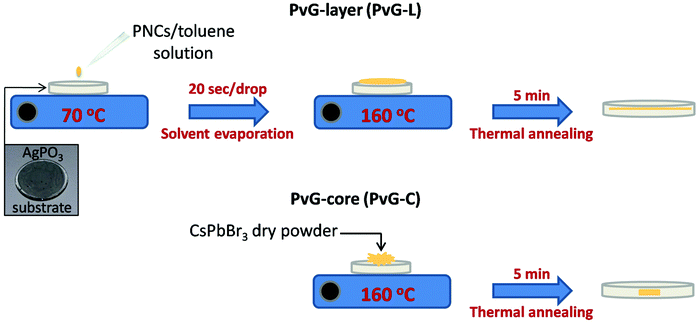
Silver metaphosphate glass (AgPO3) was prepared by melting equimolar amounts of high-purity AgNO3 (99.995%) and NH4H2PO4 (99.999%) dry-powders in a platinum crucible by following a well-established previously described synthesis route.41,42 All weighing and mixing manipulations of the two powders were performed within a glove bag purged with dry nitrogen gas. Following mixing, the melting batch was transferred to an electrical furnace initially held at 170 °C, and slowly heated up to 290 °C for the smooth removal of the volatile gas products. The furnace temperature was then increased to 450 °C and kept steady for 30 minutes with regular stirring in order to ensure melt homogeneity. AgPO3 glasses were obtained in the form of 1 mm thick disk specimens with a diameter of around 10 mm upon splat-quenching the melt between two silicon wafers. The employment of silicon wafers allows the formation of smooth glass surfaces that makes the samples suitable substrates for perovskite encapsulation. As demonstrated previously, the aforementioned melting procedure results in AgPO3 glasses with minimum water traces of less than 0.3 mol%, i.e. incapable of causing any optical or structural property modifications,41 while the samples remain unaffected by room humidity (25–30%) for several months.Two types of composite perovskite AgPO3 glasses are prepared. In the first type, isles, comprising clusters of PNCs embedded within a confined location inside the glass matrix (clustered perovskite samples, PvG-C), whereas in the second type, the incorporation of a thin perovskite layer beneath the glass surface is realized (perovskite-layer samples, PvG-L). As shown schematically in Fig. 1, the development of PvG-L from the as-prepared perovskite/toluene solution (50 mg ml−1) is based on a simple drop casting method. In particular, the AgPO3 glass substrate was positioned on a silicon wafer while a heating plate was employed to maintain a temperature of 70 °C. Several drops of the perovskite/toluene solution were added, while allowing 20 s intervals between each addition in order to ensure the gentle vaporization of the toluene solvent and the formation of the solid perovskite precipitate. Following this, the temperature was increased to 160 °C for 5 minutes, i.e. 32 °C below the glass transition temperature of the phosphate glass. At this temperature the AgPO3 glass gains viscosity and allows the smooth incorporation of the perovskite layer within the glass matrix. After the perovskite layer immersion was completed, the silicon wafer with the PvG-L sample was instantly removed from the heating plate and left to cool down to room temperature. Upon this post-annealing quenching the composite PvG-L glass solidifies again, while it can be readily retrieved from the silicon wafer.
Rather differently, the synthesis route of the composite PvG-C is based on encapsulating dry powder of PNCs within phosphate glass. In this case, the perovskite/toluene solution is dried under ambient conditions in order to yield PNCs in the form of powder. Then, around 50 mg of the extracted dry powder is positioned at the middle of the surface of the AgPO3 substrate and the sample is heated at 160 °C for 5 minutes (Fig. 1). This allows the total immersion of the perovskite powder within the glass, while the upper surface of the sample is splat-quenched and regenerates readily after the incorporation process is over. Immediately after this the composite sample is removed from the hot plate and allowed to cool down to room temperature.
Material characterization
Scanning electron microscopes (JEOL, JSM-7000F and JSM-6490) equipped with an INCA PentaFET-x3 EDS detector for energy-dispersive X-ray spectroscopy were employed for the examination of the obtained composite PvG samples, whereas their crystalline nature was studied by means of X-ray diffraction (XRD). For the XRD measurements an X-Ray Rigaku (D/max-2000) diffractometer was used, which was operated with a continuous scan of Cu Ka1 radiation with λ equal to 1.54056 Å. All XRD scans were captured at a scan rate of 0.2° s−1. The morphology of the glass embedded PNCs was studied by transmission electron microscopy (TEM, LaB6 JEOL 2100), after depositing drops of glass-powder/toluene solution onto a carbon-coated TEM grid. Room temperature Raman spectroscopy was performed in order to explore phosphate glass network modifications upon perovskite encapsulation. Raman spectra with a resolution of 1 cm−1 were recorded in the backscattering geometry after employing a 532 nm laser for excitation. A PerkinElmer UV/VIS (Lambda 950) spectrophotometer was used to investigate the optical absorption properties of the perovskite glasses over the wavelength range of 280–850 nm.For the room temperature photoluminescence measurements a previously described micro-photoluminescence (μ-PL) setup operating in the backscattering geometry was employed.44 The employed excitation source is a diode-pumped solid-state (DPSS) laser, Nd:YAG 473 nm (photon energy: 2.62 eV). The laser beam passes through a short pass (SP) filter (475 nm) in order to reduce noise at higher wavelengths, while the laser power is controlled via a neutral density (ND) filter. A 70![[thin space (1/6-em)]](https://www.rsc.org/images/entities/char_2009.gif) :
:![[thin space (1/6-em)]](https://www.rsc.org/images/entities/char_2009.gif) 30 beam splitter is used to reflect and drive the beam to the 50× objective lens, which focuses the spot size down to ∼1 μm for sample excitation. The position of the PvG glasses was controlled with a XYZ mechanical translation stage. Following the excitation, the emitted PL signal passes through a Raman edge filter (473 nm) for the elimination of laser emission. An iHR-320 spectrometer (Horiba Scientific/Jobin Yvon Technology) was used to record the PL spectra.
30 beam splitter is used to reflect and drive the beam to the 50× objective lens, which focuses the spot size down to ∼1 μm for sample excitation. The position of the PvG glasses was controlled with a XYZ mechanical translation stage. Following the excitation, the emitted PL signal passes through a Raman edge filter (473 nm) for the elimination of laser emission. An iHR-320 spectrometer (Horiba Scientific/Jobin Yvon Technology) was used to record the PL spectra.
Perovskite micropatterns
For the formation of perovskite micropatterns, a 455 nm continuous wave (cw) laser was employed, capable of providing power up to 2 W. An optical lens was used to adjust the focus of the laser beam on the glass surface. The laser source was mounded on motorized stages (XY) that allowed its accurate movement by means of custom-made computer software, while the glass sample was kept steady under the laser beam pathway. This simple laser experimental setup allows the development of encapsulated perovskite micropatterns within a few seconds, while permitting the convenient control of the pattern's periodicity and dimensions. Finally, the fluorescence properties of the composite perovskite glasses and the encapsulated perovskite micropatterns were studied using a typical fluorescence microscope by irradiating the samples with a UV light source.3. Results and discussion
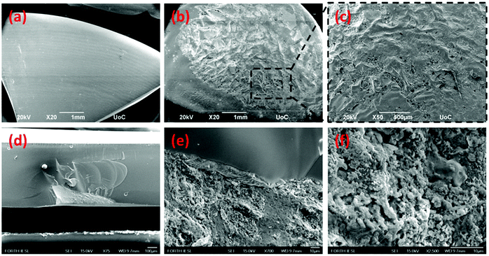
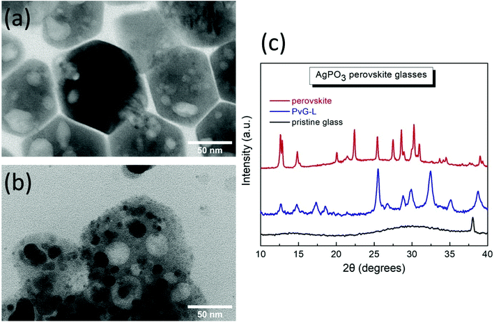
Fig. 2a presents a scanning electron microscopy (SEM) image of the pristine AgPO3 substrate, whereas Fig. 2b and c show the surface of the PvG-L glass following perovskite inclusion. Inspection of Fig. 2b reveals evidence of the perovskite vitrification in almost the entire surface of the PvG-L sample. This observation is also confirmed by the corresponding EDS elemental mapping analysis (Fig. S1†). Corresponding cross-sectional SEM photographs (Fig. S2†) reveal that the thickness of the immersed perovskite layer does not exceed 1 μm. Notably, during encapsulation, the soft glass surrounds the PNC layer without leaving visible pores on the composite glass surface. Fig. 2d depicts a cross-section image of the perovskite-core sample (PvG-C) where the perovskite isle is visible and located ∼10 μm beneath the glass surface. The maximum depth of the perovskite isle within the host glass is of the order of 200 μm. Fig. 2e presents a closer view of the perovskite/glass threshold, while Fig. 2f shows a magnified area of the perovskite region. It becomes apparent from the latter SEM figures show that the AgPO3 glass forms a smooth boundary around the perovskite material and there is no evidence of phosphate glass penetration into the perovskite isle.In order to reveal information about the nature of the encapsulated PNCs we consider transmission electron microscopy (TEM) results and XRD analysis. Fig. 3a presents a typical TEM image of the as-prepared PNCs, whereas Fig. 3b depicts the corresponding profile after incorporation to form the PvG-L glass. Inspection of TEM images reveals that the initial shape of the nanohexagons (Fig. 3a) is partially retained following encapsulation into the glass matrix (Fig. 3b). Notably, TEM profiles of the embedded nanocrystals within PvG-L and PvG-C samples were found to be indistinguishable, suggesting that the encapsulation protocol had no effect on the nature of the incorporated particles. The obtained white large spots on the particles are attributed to the interaction of the HRTEM electron beam with the perovskite nanohexagons. In fact, soon after the HRTEM beam irradiation starts the nanohexagons are affected until they are totally damaged. Such hollow regions as a result of beam damage have also been reported by other groups for similar nanomaterials.45,46 Moreover, the corresponding XRD patterns in Fig. 3c show that the as-synthesized PNCs consist mainly of the rhombohedral Cs4PbBr6 phase (01-073-2478), while a secondary and strongly photoluminescent orthorhombic CsPbBr3 phase (ICSD 97851) is also present.47–49 The presence of both phases also within the composite PvG-L glass is confirmed by the corresponding XRD profile, as depicted in Fig. 3c. In particular, the XRD pattern of the PvG-L glass retains both characteristic peaks at 12.6° and 14.8° attributed to the (110) and (100) facets of Cs4PbBr6 and CsPbBr3 phases, respectively.47–49 However, due to the thermal annealing induced during the incorporation process, some additional XRD peaks are observed for the nanocrystals embedded into the PvG-L sample, possibly attributed to the inevitably newly created phases upon heating. This could also plausibly explain the darker spots that appeared within the embedded nanohexagons, as shown in the TEM image of Fig. 3b.
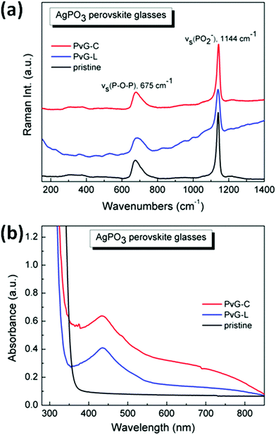
Raman spectroscopy was employed to probe any structural modifications of the phosphate glass network, upon perovskite encapsulation. Fig. 4a presents the room temperature Raman spectrum of the pristine AgPO3 glass, and the corresponding spectra of the two composite glasses PvG-L and PvG-C, respectively. It is well known that the metaphosphate network of the AgPO3 glass consists mainly of chains, which are formed by connected phosphate tetrahedral units with bridging and non-bridging (terminal) oxygen atoms.41,42,50,51 The two main Raman features shown in Fig. 4a are distinct signatures of such structural units. In particular, the key band at ca. 1144 cm−1 is attributed to the symmetric stretching vibration of terminal PO2− groups, vs(PO2−), whereas the broader band at ca. 675 cm−1 originates from the symmetric stretching movement of P–O–P bridges within the phosphate backbone, vs(P–O–P). The relative intensities of these two Raman bands provide direct evidence in the case wherein the population of terminal or bridging phosphate species changes at the expense of the other upon the incorporation of PNCs. As for instance, if oxygen was to be detached from the phosphate network, the population of P–O–P bridges would increase relative to that of terminal PO2− groups. The spectra of Fig. 4a are normalized at the strongest band at 1144 cm−1 in order to facilitate comparison. Notably, inspection of Fig. 4a reveals no significant change in the relative intensities of the Raman features of the PvG-L and PvG-C samples, when compared to the corresponding spectrum of pristine AgPO3 glass. This observation implies that in both types of composite glasses, the encapsulation of perovskite crystals has no effect on the connectivity of the phosphate glass network, and thus, no direct incorporation of additional oxygen from the phosphate network to the perovskite lattice occurs. This holds good despite the formation of newly created PNC phases during encapsulation heating. However, in the case of the PvG-L sample where the perovskite layer is widely spread near the surface, it appears to give rise to Raman activity below 250 cm−1, a region where Raman modes have been previously attributed to structural vibrations of lead-containing all-inorganic perovskite crystals.52,53
Although the incorporation of PNCs does not cause any noticeable structural modification to the phosphate network, it definitely alters the optical properties of the composite glasses. Fig. 4b shows the respective optical absorbance spectra. As expected from previous studies, the pristine binary AgPO3 glass is almost transparent, down to 380 nm.37 Rather differently, both PvG-L and PvG-C samples exhibit the characteristic absorption shoulder of the orthorhombic CsPbBr3 phase at around 510 nm (Fig. S3†).47–49 Notably, a more pronounced absorption is observed for the latter sample where the considerably thicker perovskite core is present. Both composite glasses also exhibit absorption profiles in the vicinity of 440 nm that are attributed to the formation of metallic silver nanoparticles due to the thermal annealing that occurred during encapsulation.37 It is also shown that the integration of perovskite crystals pushes the absorbance threshold of the composite glasses to slightly lower wavelengths of around 350 nm, due to the enhancement of light absorption within the glass matrix. Nevertheless, the characteristic low-wavelength absorption feature of the Cs4PbBr6 species at around 315 nm is not observed for any of the two composite glasses,47–49 as the binary AgPO3 phosphate glass is not transparent in that wavelength.
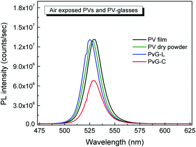
Remarkably, the inclusion of PNCs within the phosphate glass induces impressive photoluminescence properties. Fig. 5 presents typical photoluminescence (PL) spectra of the two composite glasses PvG-L and PvG-C. Both composite glasses exhibit the characteristic green PL feature of orthorhombic CsPbBr3 nanocrystals at around 525 nm.47–49 In addition, Video S1† illustrates the obtained transition of the green light photoluminescence upon moving the blue laser excitation source of the μ-PL setup inside and outside the confined perovskite isle of the PvG-C sample. It is emphasized that such a PL profile is totally absent from the spectrum of the pristine AgPO3 glass, as well as when a region outside the perovskite core of the PvG-C sample is excited (Video S1†). Fig. 5 also presents the corresponding PL spectra of an air-exposed perovskite film that is formed on the surface of AgPO3 glass by the same drop-casting method that was used for the synthesis of the composite PvG-L sample. The PL profile of the air-exposed perovskite dry powder is also included in the same figure. A slight blue shift of a few nm is noted for the PL signature of the PvG-L glass when compared to the reference film, suggesting a possible decrease in the size of the PNCs upon vitrification,47 possibly induced by the compression from the phosphate glass network. Impressively though, the perovskite layer encapsulation within the phosphate glass matrix turns out to be of excellent photoluminescence efficiency, as it causes negligible losses in the PL intensity. Rather differently, in the case of PvG-C glass the encapsulation of the perovskite dry powder induces a PL loss of around 40% (Fig. 5). Since the perovskite isle is entirely beneath the glass surface, the obtained luminescence losses might be attributed to scattering effects induced by the silver phosphate glass matrix that completely covers the confined luminescent isle.37
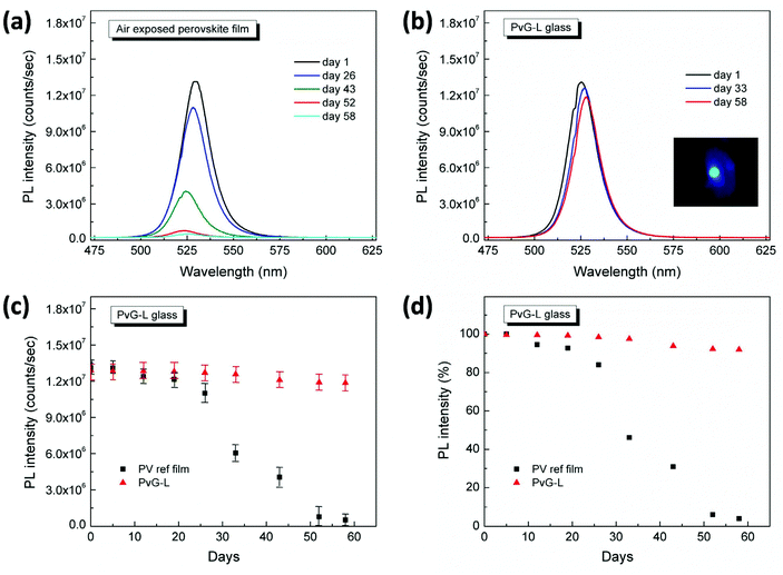
An even more remarkable feature of the developed PvG-L and PvG-C glasses lies in their impressive PL stability over time. Fig. 6a depicts the indicative PL spectra of the air-exposed reference film over a period of two months, whereas Fig. 6b presents the corresponding spectra of the PvG-L glass sample. The inset of Fig. 6b also shows a photograph of the green PL of the PvG-L sample captured at day one, while some scattering of the blue excitation laser is also visible. The actual PL intensities of the perovskite film and the PvG-L glass as a function of days of exposure to air are plotted in Fig. 6c, while maintaining all spectra acquisition conditions identical. The corresponding peak PL intensity, in terms of percentage with respect to the maximum intensity recorded on the first day, is plotted in Fig. 6d. Inspection of the latter two figures reveals that during the period of two months the PL intensity of the PvG-L sample exhibits only minimal losses of 8%, in contrast to the air-exposed film that exhibits significant losses of 96%. Even within the first month, the PvG-L glass retains around 97% of the its initial PL intensity value, whereas the air-exposed film exhibits losses of 55% within the same period. The impressive PL stability, together with the aforementioned efficiency of the encapsulation process, demonstrate the suitability of the proposed fabrication method towards the development of highly luminescent and stable encapsulated perovskite patterns within PvG-L samples.
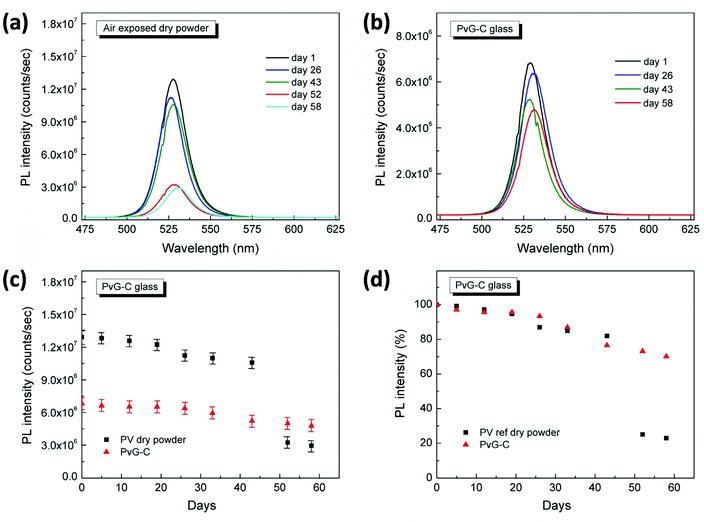
Along similar lines, the PL stability of the PvG-C glass has been investigated. Fig. 7a shows the PL spectra of the air-exposed dry perovskite powder at various time intervals, whereas the corresponding indicative spectra of the PvG-C glass are shown in Fig. 7b. Fig. 7c and d present respectively the variation of PL intensity over time and the corresponding percentage with respect to the initial intensity recorded on the first day. Inspection of Fig. 7d reveals that the PL intensity of the air-exposed dry powder drops to 23% within two months, whereas the corresponding intensity of the PvG-C sample is maintained at 70% of the initial value within the same period. These findings imply, that despite being a less efficient inclusion method when compared to that for PvG-L, the core encapsulation still offers an important shield over the degradation of perovskite crystals upon exposure to ambient air.
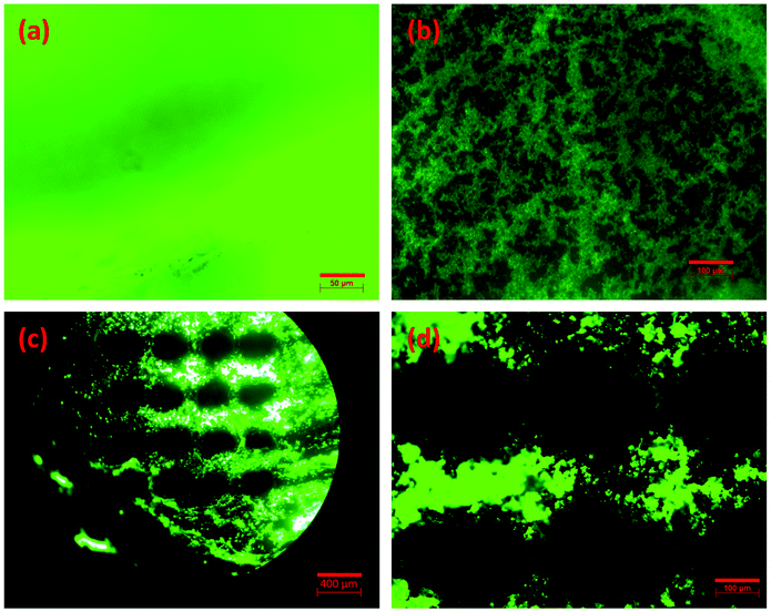
As a final part of this study, we demonstrate the development of encapsulated luminescent perovskite micropatterns within the fabricated composite glasses by means of a simple cw laser patterning process. Fig. 8a presents a fluorescence microscopy image of the PvG-C glass within the confined location of the incorporated perovskite core, whereas Fig. 8b depicts an indicative photograph of the PvG-L glass before patterning. Notably, both perovskite glasses are highly luminescent under the UV lamp irradiation. However, among the two composite samples, the PvG-L glass is more suitable for laser inscription of patterns on the thin luminescent layer, instead of attempting to create patterns on the considerably thicker perovskite core.
Fig. 8c and d show fluorescence photographs of micro-dotted optical textures within PvG-L glasses after performing laser patterning with a cw, 455 nm laser. The adopted irradiation pattern is represented schematically in Fig. S4.† Namely, the laser beam initially moves horizontally, followed by vertical movement after completing dots of the first line. The distance between the dots is defined by the horizontal and vertical separation steps (Fig. S4†), while the diameter of the dots is readily controlled by the spot size of the employed laser. In this manner, the shape and size of the pattern can be varied in accordance to the irradiation pathway and beam profile. In particular, Fig. 8c presents a luminescent micro-dotted optical texture with a horizontal separation step of 400 μm and a vertical separation step of 500 μm, while Fig. 8d depicts a similar pattern with smaller separation steps of 300 μm and 400 μm, respectively. In both patterns, the dark dots are created upon laser irradiation with a power of 1.6 W for 100 ms, while the beam diameter is 250 μm. These irradiation conditions resulted in the confined degradation of the incorporated PNCs. Consequently, the green luminescence within the irradiated spots disappears. In contrast, the non-irradiated region between the dark dots remains highly luminescent. Fig. S5† presents the PL spectra of PvG-L glass before and after laser processing, where the latter PL spectrum is recorded for a non-irradiated region between the dark dots (Fig. 8c). The negligible differences between the two spectra shown in Fig. S5† strongly imply that the embedded PNCs outside the irradiation spots maintain their structure and photoluminescence properties. Finally, it is emphasized that based on the aforementioned procedures, the developed patterning process requires only widely available, compact, and low-cost cw laser sources, while being extremely fast and efficient.
4. Conclusions
In conclusion, we herein demonstrate a simple and low temperature post-glass quenching method for the development of composite perovskite glasses by incorporating pre-synthesized PNCs within a transparent phosphate glass matrix. The proposed novel two-step method enables controlled positioning of the PNCs for the formation of a perovskite layer or a perovskite isle within the glass matrix. Both types of glasses exhibit remarkable photoluminescence stability over time when compared to the air-exposed perovskite crystals, while the glass encapsulation resolves environmental concerns of lead. Based on this, the described vitrification procedure is proven to be suitable for stabilizing perovskites within a transparent visible optical medium. Furthermore, by means of a simple and fast cw laser processing technique the formation of encapsulated highly luminescent and stable perovskite periodic patterns was achieved. The architecture of these patterns can be easily modified according to the needs of the targeted application by simply altering the processing conditions. Based on the above, the presented synthesis route is expected to open up new ways towards the development of advanced composite perovskite-glass architectures for various photonic applications.Conflicts of interest
There are no confilcts to declare.Acknowledgements
This work was partially supported by the “HELLAS-CH (MIS 5002735)”implemented under the “Action for Strengthening Research and Innovation Infrastructures”, funded by the Operational Programme “Competitiveness, Entrepreneurship and Innovation” (NSRF 2014-2020) and co-financed by Greece and the European Union “(European Regional Development Fund)”. The funding scheme European Research Infrastructure NFFA-Europe, funded by EU's H2020 Framework Program for research and innovation under grant agreement No. 654360 is also acknowledged. AK and KB thank the Hellenic Foundation for Research and Innovation (HFRI) and the General Secretariat for Research and Technology (GSRT) for funding this project under grant agreement No. 1179. IK is grateful to Mr Andreas Lemonis (IESL-FORTH) for his assistance with laser patterning experimental setup. We would like to also thank the Electron Microscopy Laboratory of the University of Crete for providing access to HRTEM and SEM facilities.References
- A. Kojima, K. Teshima, Y. Shirai and T. Miyasaka, J. Am. Chem. Soc., 2009, 131, 6050 CrossRef CAS PubMed.
- H. J. Snaith, J. Phys. Chem. Lett., 2013, 4, 3623 CrossRef CAS.
- P. Gao, M. Grätzel and M. K. Nazeeruddin, Energy Environ. Sci., 2014, 7, 2448 RSC.
- A. Kostopoulou, K. Brintakis, N. K. Nasikas and E. Stratakis, Nanophotonics, 2019, 8, 1607 CAS.
- P. Tan, M. Liu, Z. Shao and M. Ni, Adv. Energy. Mater, 2017, 7, 1602674 CrossRef.
- A. Kostopoulou, D. Vernardou, K. Savva and E. Stratakis, Nanoscale, 2019, 11, 882 RSC.
- L. Dou, Y. Yang, J. You, Z. Hong, W.-H. Chang, G. Li and Y. Yang, Nat. Commun., 2014, 5, 5404 CrossRef CAS PubMed.
- Y. Fang, Q. Dong, Y. Shao, Y. Yuan and J. Huang, Nat. Photonics, 2015, 9, 679 CrossRef CAS.
- M. Ahmadi, T. Wu and B. Hu, Adv. Mater., 2017, 29, 1605242 CrossRef.
- S. D. Stranks and H. J. Snaith, Nat. Nanotechnol., 2015, 10, 391 CrossRef CAS.
- M. I. Saidaminov, J. Almutlaq, S. Sarmah, I. Dursun, A. A. Zhumekenov, R. Begum, J. Pan, N. Cho, O. F. Mohammed and O. M. Bakr, ACS Energy Lett., 2016, 1, 840 CrossRef CAS.
- E. Y. Tiguntseva, G. P. Zograf, F. E. Komissarenko, D. A. Zuev, A. A. Zakhidov, S. V. Makarov and Y. S. Kivshar, Nano Lett., 2018, 18, 1185 CrossRef CAS PubMed.
- G. Xing, N. Mathews, S. S. Lim, N. Yantara, X. Liu, D. Sabba, M. Grätzel, S. Mhaisalkar and T. C. Sum, Nat. Mater., 2014, 13, 476 CrossRef CAS PubMed.
- Y. Fu, H. Zhu, C. C. Stoumpos, Q. Ding, J. Wang, M. G. Kanatzidis, X. Zhu and S. Jin, ACS Nano, 2016, 10, 7963 CrossRef CAS PubMed.
- H.-C. Wang, S.-Y. Lin, A.-C. Tang, B. P. Singh, H.-C. Tong, C.-Y. Chen, Y.-C. Lee, T.-L. Tsai and R. S. Liu, Angew. Chem., Int. Ed., 2016, 55, 7924 CrossRef CAS PubMed.
- M. Grätzel, Nat. Mater., 2014, 13, 838 CrossRef PubMed.
- B. Hailegnaw, S. Kirmayer, E. Edri, G. Hodes and D. Cahen, J. Phys. Chem. Lett., 2015, 6, 1543 CrossRef CAS PubMed.
- P. Docampo and T. Bein, Acc. Chem. Res., 2016, 49, 339 CrossRef CAS PubMed.
- L. Protesescu, S. Yakunin, M. I. Bodnarchuk, F. Krieg, R. Caputo, C. H. Hendon, R. X. Yang, A. Walsh and M. V. Kovalenko, Nano Lett., 2015, 15, 3692 CrossRef CAS PubMed.
- S. Pathak, N. Sakai, F. W. R. Rivarola, S. D. Stranks, J. Liu, G. E. Eperon, C. Ducati, K. Wojciechowski, J. T. Griffiths, A. A. Haghighirad, A. Pellaroque, R. H. Friend and H. J. Snaith, Chem. Mater., 2015, 27, 8066 CrossRef CAS.
- Y. Wang, J. He, H. Chen, J. Chen, R. Zhu, P. Ma, A. Towers, Y. Lin, A. J. Gesquiere, S.-T. Wu and Y. Dong, Adv. Mater., 2016, 28, 10710 CrossRef CAS PubMed.
- S. N. Raja, Y. Bekenstein, M. A. Koc, S. Fischer, D. Zhang, L. Lin, R. O. Ritchie, P. Yang and A. P. Alivisatos, ACS Appl. Mater. Interfaces, 2016, 8, 35523 CrossRef CAS PubMed.
- P. Li, C. Hu, L. Zhou, J. Jiang, Y. Cheng, M. He, X. Liang and W. Xiang, Mater. Lett., 2017, 209, 483 CrossRef CAS.
- S. Yuan, D. Chen, X. Li, J. Zhong and X. Xu, ACS Appl. Mater. Interfaces, 2018, 10, 18918 CrossRef CAS PubMed.
- S. Liu, M. He, X. Di, P. Li, W. Xiang and X. Liang, Ceram. Int., 2018, 44, 4496 CrossRef CAS.
- D. Chen, S. Yuan, J. Chen, J. Zhong and X. Xu, J. Mater. Chem. C, 2018, 6, 12864 RSC.
- Y. Ye, W. Zhang, Z. Zhao, J. Wang, C. Liu, Z. Deng, X. Zhao and J. Han, Adv. Opt. Mater, 2019, 1801663 CrossRef.
- P. Li, W. Xie, W. Mao, Y. Tian, F. Huang, S. Xu and J. Zhang, J. Alloys Compd., 2020, 817, 153338 CrossRef CAS.
- Y. Wang, R. Zhang, Y. Yue, S. Yan, L. Zhang and D. Cheng, J. Alloys Compd., 2020, 818, 152872 CrossRef CAS.
- F. Zheng, B. Yang, P. Cao, X. Qian and J. Zou, J. Alloys Compd., 2020, 818, 153307 CrossRef CAS.
- Z. Zhang, L. Shen, Y. Zhao, Y. Zhang, H. Yang, W. Xiang, X. Liang, G. Chen and H. Yu, Chem. Eng. J., 2020, 385, 123415 CrossRef.
- X. Huang, Q. Guo, S. Kang, T. Ouyang, Q. Chen, X. Liu, Z. Xia, Z. Yang, Q. Zhang, J. Qiu and G. Dong, ACS Nano, 2020, 14, 3150 CrossRef CAS PubMed.
- X. Li, C. Yang, Y. Yu, Z. Li, J. Lin, X. Guan, Z. Zheng and D. Chen, ACS Appl. Mater. Interfaces, 2020, 12, 18705 CrossRef CAS PubMed.
- M. P. Arciniegas, A. Castelli, S. Piazza, S. Dogan, L. Ceseracciu, R. Krahne, M. Duocastella and L. Manna, Adv. Funct. Mater., 2017, 27, 1701613 CrossRef.
- C. Zou, J. Zheng, C. Chang, A. Majumdar and L. Y. Lin, Adv. Opt. Mater, 2019, 7, 1900558 CrossRef.
- G. Papon, N. Marquestaut, Y. Petit, A. Royon, M. Dussauze, V. Rodriguez, T. Cardinal and L. Canioni, J. Appl. Phys., 2014, 115, 113103 CrossRef.
- I. Konidakis, S. Psilodimitrakopoulos, K. Kosma, A. Lemonis and E. Stratakis, Opt. Mater., 2018, 75, 796 CrossRef CAS.
- D. Pugliese, N. G. Boetti, J. Lousteau, E. Ceci-Ginistrelli, E. Bertone, F. Geobaldo and D. Milanese, J. Alloys Compd., 2016, 657, 678 CrossRef CAS.
- I. Konidakis, G. Zito and S. Pissadakis, Opt. Lett., 2014, 39, 3374 CrossRef CAS PubMed.
- C. Jain, B. P. Rodrigues, T. Wieduwilt, J. Kobelke, L. Wondraczek and M. A. Schmidt, Opt. Express, 2016, 24, 3258 CrossRef CAS PubMed.
- I. Konidakis, C. P. E. Varsamis and E. I. Kamitsos, J. Non-Cryst. Solids, 2011, 357, 2684 CrossRef CAS.
- D. Palles, I. Konidakis, C. P. E. Varsamis and E. I. Kamitsos, RSC Adv., 2016, 6, 16697 RSC.
- A. Kostopoulou, K. Brintakis, E. Serpetzoglou and E. Stratakis, Nanomaterials, 2020, 10, 747 CrossRef CAS PubMed.
- I. Demeridou, I. Paradisanos, Y. Liu, N. Pliatsikas, P. Patsalas, S. Germanis, N. T. Pelekanos, W. A. Goddard III, G. Kioseoglou and E. Stratakis, 2D Mater., 2019, 6, 015003 CrossRef CAS.
- Z. Dang, J. Shamsi, F. Palazon, M. Imran, Q. A. Akkerman, S. Park, G. Bertoni, M. Prato, R. Brescia and L. Manna, ACS Nano, 2017, 11, 2124 CrossRef CAS PubMed.
- Z. Dang, J. Shamsi, Q. A. Akkerman, M. Imran, G. Bertoni, R. Brescia and L. Manna, ACS Omega, 2017, 2, 5660 CrossRef CAS PubMed.
- Q. A. Akkerman, S. Park, E. Radicchi, F. Nunzi, E. Mosconi, F. De Angelis, R. Brescia, P. Rastogi, M. Prato and L. Manna, Nano Lett., 2017, 17, 1924 CrossRef CAS PubMed.
- F. Palazon, C. Urso, L. De Trizio, Q. A. Akkerman, S. Marras, F. Locardi, I. Nelli, M. Ferretti, M. Prato and L. Manna, ACS Energy Lett., 2017, 2, 2445 CrossRef CAS PubMed.
- Q. Jing, Y. Xu, Y. Su, X. Xing and Z. Lu, Nanoscale, 2019, 11, 1784 RSC.
- A. Fontana, F. Rossi, C. Armellini, G. Dangelo, G. Tripodo and A. Bartolotta, Philos. Mag. B, 1999, 79, 2073 CrossRef CAS.
- R. K. Brow, J. Non-Cryst. Solids, 2000, 263, 1 CrossRef.
- J. Yin, Y. Zhang, A. Bruno, C. Soci, O. M. Bakr, J.-L. Bredas and O. F. Mohammed, ACS Energy Lett., 2017, 2, 2805 CrossRef CAS.
- Z. Qin, S. Dai, V. G. Hadjiev, C. Wang, L. Xie, Y. Ni, C. Wu, G. Yang, S. Chen, L. Deng, Q. Yu, G. Feng, Z. M. Wang and J. Bao, Chem. Mater., 2019, 31, 9098 CrossRef CAS.
Footnote |
| † Electronic supplementary information (ESI) available. See DOI: 10.1039/d0nr03254a |
| This journal is © The Royal Society of Chemistry 2020 |

