DOI:
10.1039/C9NR10591C
(Paper)
Nanoscale, 2020,
12, 6673-6690
Effect of hydrodynamic inter-particle interaction on the orbital motion of dielectric nanoparticles driven by an optical vortex†
Received
15th December 2019
, Accepted 21st January 2020
First published on 24th January 2020
Abstract
We experimentally and theoretically characterize dielectric nano- and microparticle orbital motion induced by an optical vortex of the Laguerre–Gaussian beam. The key to stable orbiting of dielectric nanoparticles is hydrodynamic inter-particle interaction and microscale confinement of slit-like fluidic channels. As the number of particles in the orbit increases, the hydrodynamic inter-particle interaction accelerates orbital motion to overcome the inherent thermal fluctuation. The microscale confinement in the beam propagation direction helps to increase the number of trapped particles by reducing their probability of escape from the optical trap. The diameter of the orbit increases as the azimuthal mode of the optical vortex increases, but the orbital speed is shown to be insensitive to the azimuthal mode, provided that the number density of the particles in the orbit is same. We use experiments, simulation, and theory to quantify and compare the contributions of thermal fluctuation such as diffusion coefficients, optical forces, and hydrodynamic inter-particle interaction, and show that the hydrodynamic effect is significant for circumferential motion. The optical vortex beam with hydrodynamic inter-particle interaction and microscale confinement will contribute to biosciences and nanotechnology by aiding in developing new methods of manipulating dielectric and nanoscale biological samples in optical trapping communities.
Introduction
The optical vortex was proposed by Allen et al.1–3 and had a ring-like transverse intensity distribution and optical angular momentum. This feature of the optical vortex drives the orbital motion of target particles along the ring-like intensity distribution, where the ring trapping and orbital motion are mainly caused by the optical gradient and scattering forces, respectively. Experiments have been done on the orbital motion of non-biological particles, especially latex beads with diameters of a few micrometers,4–12 metal particles with diameters of several hundred nanometers to a few micrometers,13–17 and glass or silica particles.18,19 Some theoretical studies and modeling20–23 have also been conducted. The theoretical studies20,22 have involved multiple orbiting particles accelerated by hydrodynamic interaction between non-Brownian particles20 and light-induced interaction between gold nanoparticles.22 Plasmonic nanoparticles such as gold nanoparticles are relatively easy to manipulate optically because of their high polarizability. However, dielectric nanoparticles, which have low polarizability, have been rarely reported for a diameter less than one micrometer, because smaller particles are more difficult to stably trap in an orbit owing to the significant thermal fluctuation and weak optical forces. Because some target particles in biomedical applications (such as viruses24,25) are dielectric and have a characteristic length of several tens or hundreds of nanometers, manipulation of dielectric Brownian nanoparticles with an optical vortex should be explored for treating nano-scale biological samples. It should be noted that the optical vortex has been applied not only to the orbital motion of target particles but also to fabricating chiral nano-structures such as metal needles,26,27 polymer needles,28,29 and helical plastic fibers.30 Therefore, developing technologies using the optical vortex will contribute to various research fields such as biosciences and nanofabrication.
Given such growing interest in the field, this paper addresses techniques for improving particle manipulation technologies and validates them both experimentally and theoretically. The novel aspect is that the technique is not based on optics but rather on mechanics. We systematically investigate the optical-vortex-induced motion of dielectric micro- and nanoparticles with diameters ranging from 0.2 μm to 2 μm, which includes biological scales from viruses to cells. The two key ideas for the successful optical manipulation of nanoparticles are hydrodynamic inter-particle interaction and microscale confinement of slit-like fluidic channels. We find that the number of particles trapped in an orbit is important in the dynamics of orbital motion: the orbiting speed increases with the number of nanoparticles. This acceleration is schematically described in Fig. 1 and the ESI (Movie S1†). A theoretical model including hydrodynamic interaction8,10–12,20 explained the qualitative characteristics of microparticle motion observed in experiments. The diameter of the orbit increases as the azimuthal mode of the optical vortex increases, but the orbital speed is shown to be insensitive to the azimuthal mode, provided that the number density of the particles in the orbit is same. Such a trend is shown to be closely related to the above-mentioned hydrodynamic interaction. It should be noted that when a perfect vortex beam31,32 is used, the diameter of the orbit is independent of the azimuthal mode, and the orbital speed increases linearly as the azimuthal mode increases. For the stable orbital motion of the smallest particle investigated in this paper, which has a diameter of 0.2 μm, hydrodynamic inter-particle interaction is required to accelerate its speed enough to overcome the inherent thermal fluctuation, which is significant for nanoscale targets. Evaluating the orbital motion of such tiny particles is facilitated by using microchannels with a small height, high-precision flow control, and a mixture of non-fluorescent and fluorescent particles. In particular, channels with a small height that confine the motion to two dimensions reduce the chance that nanoparticles will escape the optical trap in the beam propagation direction, leading to a larger number of orbiting particles and thus enhancing orbiting speed.
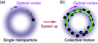 |
| | Fig. 1 Concept of orbiting acceleration due to hydrodynamic inter-particle interaction. (a) It is difficult to manipulate a single dielectric nanoparticle because of the weak optical force and inherent thermal fluctuation. However, when the number of particles in the orbit increases, as shown in panel (b), the collective nanoparticle motion leads to faster orbital speed that overcomes the thermal fluctuation. | |
Micro- and nanofluidic devices can be used to analyze target biological nanoparticles and/or molecules dispersed in fluids.33 Various methods to control target motion have been proposed to overcome the difficulties of controlling nanoscale targets.34 Among them, optical forces have attracted much attention because they are a non-contact and feasible method available to researchers in various fields.35–41 In fact, optical manipulation of tiny particles or biomolecules has been a fundamental tool in state-of-the-art nanoscience and bioengineering ever since the discovery of optical trapping by Ashkin.42 The method proposed in this paper enhances the controllability of nanoscale dielectric targets and contributes to the development of micro- and nanofluidic devices. Optical manipulation, electrophoresis,43 and thermophoresis44–46 are useful transport phenomena in tiny devices and have different physical mechanisms, so combining them will yield a selective manipulation method.47,48
Experimental methods
Optical setup
An overview of the experimental setup is shown in Fig. 2. First, an observation system is introduced. A microfluidic device is mounted on an inverted microscope (IX-71, Olympus, Tokyo, Japan). The details of the device will be explained later. An objective lens (OL) with a magnification of 20× (numerical aperture (NA) = 0.45, LCPLN20XIR, Olympus, Tokyo, Japan) or 50× (NA = 0.65, LCPLN50XIR, Olympus, Tokyo, Japan) is used to observe the particle motion in the device. Our sample solution is contained in a microchannel with a height h ≈ 3 μm. Therefore, a high NA such as that of an oil immersion lens, which is frequently used in optical trapping, is not necessary because confinement prevents the target particles from being pushed out in the direction of beam propagation, resulting in stable trapping. An excitation light (Cobolt 06-MLD, Cobolt AB, Solna, Sweden) with a wavelength of 488 nm for fluorescence observation irradiates the device through the same OL. Fluorescence from a sample, which is a polystyrene particle described in Table 1, is monitored with a complementary-metal–oxide–semiconductor (CMOS) camera (Zyla 5.5, Andor Technology, Belfast, Northern Ireland) and analyzed with a personal computer (PC). A transmission light source (TLS) may be also used to observe non-fluorescent samples.
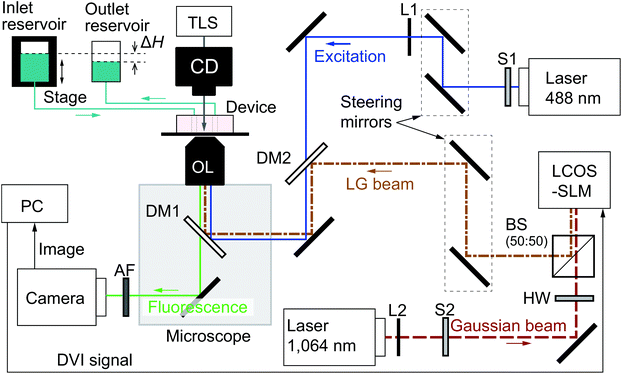 |
| | Fig. 2 Schematic of the experimental setup. AF: absorption filter to cut the laser with a wavelength of 1064 nm. BS: beam splitter. CD: condenser. DM1 and DM2: dichroic mirrors. DVI: digital visual interface. HW: half-wave plate to adjust the direction of linear polarization to that required by the liquid-crystal-on-silicon spatial-light-modulator (LCOS-SLM). L1 and L2: plano-convex lenses to obtain desired beam diameters. OL: objective lens. PC: personal computer. S1 and S2: shutters. TLS: transmission light source. The inlet and outlet reservoirs are used to control the channel flow rate. The photograph of the microfluidic device on the microscope stage is presented in Fig. S1.† | |
Table 1 Product names and concentrations of polystyrene particles for the samples with dp = 0.2, 0.5, 1.0, and 2.0 μm
|
d (μm) |
Fluorescent particle (Molecular Probes, Eugene, USA) |
Non-fluorescent particle (Merck, Darmstadt, Germany) |
| Product name |
Concentration |
Product name |
Concentration |
| 0.2 |
F8811 |
2.0 × 10⁻⁴ wt% |
K1-020 |
2.0 × 10⁻² wt% |
| 0.5 |
F8813 |
2.0 × 10⁻⁴ wt% |
K1-050 |
1.5 × 10⁻² wt% |
| 1.0 |
F8823 |
2.0 × 10⁻⁴ wt% |
K100 |
1.0 × 10⁻² wt% |
| 2.0 |
F8827 |
2.0 × 10⁻⁴ wt% |
L200 |
1.0 × 10⁻² wt% |
The wavelength of the laser used in this study is 1064 nm, because this wavelength is standard and frequently used in biosciences owing to the low absorption rate of the laser beam by water solutions. The optical vortex in our experiments is the Laguerre–Gaussian (LG) beam, which is one of the higher-order modes of a Gaussian beam. The LG beam is obtained by converting a continuous-wave (CW) Gaussian beam with a wavelength of 1064 nm (ASF1JE01, Fitel, Furukawa Electronics, Tokyo, Japan) using a liquid-crystal-on-silicon spatial-light-modulator (LCOS-SLM; X13138-03, Hamamatsu Photonics K.K., Hamamatsu, Japan), as shown in Fig. 2. More specifically, the PC sends a digital-visual-interface (DVI) signal to the LCOS-SLM to show a specific image on the LCOS-SLM display. If the Gaussian beam irradiates the display, the image produces a spatially inhomogeneous phase difference from the incident beam, and then the reflected beam becomes the optical vortex. The azimuthal mode m of the optical vortex may be changed using another specific image. Before the Gaussian beam impinges on the LCOS-SLM, the direction of linear polarization of the beam must be modulated using a half-wave (HW) plate such that it is consistent with the LCOS-SLM specification. The LG beam is combined with the excitation light and introduced in the microscope. The optical power Plaser is measured at the top of the OL using a power meter (3A-QUAD, Ophir Optronics, Jerusalem, Israel).
Microfluidic device
The microfluidic device consists of a block of polydimethylsiloxane (PDMS; Sylgard®184, Dow Corning Toray Co., Tokyo, Japan) with a microchannel pattern and a cover glass (24 × 36 mm2, no. 1, Matsunami Glass Co., Osaka, Japan). First, a silicon mold that has the microchannel pattern is fabricated as described in Appendix A. Then, PDMS is poured on the mold and cured. Removing the cured PDMS from the mold results in a PDMS block with the microchannel pattern. The microchannel height is determined by the height of the silicon mold, which is measured as h = 3.2 ± 0.1 μm using a laser scanning microscope (OLS4100, Olympus, Tokyo, Japan). Then, two holes for the inlet and outlet are fabricated in the PDMS block using a biopsy punch (2.0 mm in diameter, BP-25F, Kai Industries Co., Seki, Japan). Finally, after cleaning the contact surfaces of the PDMS block and the cover glass with a corona treater (BD-20AC, Electro-Technic Products, Chicago, USA), we bond them together to form the microfluidic device.
The microchannel pattern is schematically shown in Fig. 3(a). The channel height in the z direction is denoted by h, as shown in the side view of Fig. 3(b). The center of the irradiated optical vortex is at the center of the test section. The radial coordinate of the particle is expressed as (rp, θp), as shown in Fig. 3. The azimuthal mode m of the optical vortex is defined so that dθp/dt > 0 when m > 0, where t is a time variable. The PDMS roof may collapse owing to the small microchannel height. To avoid collapse, square columns with an area of 100 × 100 μm2 are fabricated in the channel with a spatial interval of w = 100 μm in both the x and y directions.
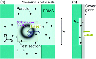 |
| | Fig. 3 Schematic of the microfluidic device. (a) Microscopic view from the bottom of the device. PDMS rectangular columns are fabricated with an interval w to avoid channel collapse. (b) Side view of the channel in the yz-plane. | |
Sample particles
The sample solution contains a mixture of fluorescent and non-fluorescent polystyrene (PS) particles with the same diameter dp. The product name and bead concentrations are listed in Table 1. For instance, for dp = 0.2 μm, the sample solution is prepared by diluting the stock solutions of the fluorescent particles (F8811) and non-fluorescent particles (K1-020) using the non-ionic surfactant solvent Triton X-100 (1 wt%). The surfactant is necessary to avoid the sticking of particles to the channel walls because our sample solution is confined to a narrow space where the particles have frequent chances to contact the wall.
The reason for using a mixture of 2.0 × 10⁻⁴ wt% dilute fluorescent particles and ≤2.0 × 10⁻² wt% dense non-fluorescent particles is to facilitate particle tracking (see Movie S1†). We optically trap both types of particles in the circular path so that a single fluorescent particle is contained. In this way, only the fluorescent particle is recognized in the particle tracking algorithm. Using such a mixture of fluorescent and non-fluorescent particles is especially important when dp is small and the number of particles in the circular path, N, is large. For the particle tracking from the obtained video images, we use an image analysis software ImageJ and its plugin Particle Track and Analysis (PTA).
Experimental procedure
All the experiments were carried out at the room temperature of 297.7 ± 1.7 K. The fluid flow in the channel should be kept negligibly small to eliminate the biased drag force acting on the particles. The fluid flow is controlled as follows. The PDMS block has an inlet hole with a diameter of 2 mm. A silicone tube connects the inlet hole to the inlet reservoir, as shown in Fig. 2. The same tube connection is also made to the outlet hole of the PDMS and the outlet reservoir. The sample solution is poured into the reservoirs, and the whole device and reservoirs are deaerated in a vacuum chamber to remove remaining bubbles in the microchannel. After the deaeration, there is an inherent water-level difference ΔH between the inlet and outlet reservoirs that induces the mean flow in the microchannel, as shown in Fig. 2. Because the unwanted mean flow can affect the analysis of particle motion induced by the optical vortex, the water-level difference ΔH is set to be zero using an automatic stage (SGSP20-35, Sigma Koki, Japan) with a precision of ΔHmin = 1 μm. Note that the pressure difference ΔP between the inlet and outlet reservoirs can be controlled with a high resolution ΔP = ρgΔHmin ≈ 0.01 Pa, where ρ = 1.0 × 10³ kg m−3 is the fluid density and g = 9.8 m s−2 is the acceleration of gravity. The complete absence of mean flow can be verified by checking the video of the PS particles. In fact, using the particle tracking velocimetry, the magnitude of mean flow is estimated as 0.2 μm s−1 at most. Then, the sample solution confined in the slit-like microchannel is irradiated by the focused LG beam in the perpendicular direction, as shown in Fig. 3.
Theoretical model
Micro- and nanofluid dynamics
In this section, we introduce a model based on the literature8,10–12,20 that accounts for hydrodynamic inter-particle interaction. These references modeled optical forces as simple heuristic functions and did not consider thermal fluctuation. The effect of thermal fluctuation may be negligible for particles with diameters larger than 2 μm in water (e.g., ref. 8 uses a particle with a diameter of 3 μm and the theoretical model without thermal fluctuation well predicted the experimental results), but it is significant for particles with a diameter of 0.2 μm. This paper uses a more realistic model of optical forces and includes the effect of thermal fluctuation to simulate particles with a diameter of 0.2 μm.
We consider the two-dimensional motion of N particles with mass mp and radius ap = dp/2 in the focal plane, which is the xy plane of the Cartesian coordinate system as shown in Fig. 3. The motion is induced by an optical vortex. The position and velocity of the nth particle (n = 1, …, N) are denoted by rn(t) = (xn(t), yn(t)) and vn(t) = (vx,n(t), vy,n(t)). We also introduce the polar coordinates (x,y) = (r![[thin space (1/6-em)]](https://www.rsc.org/images/entities/char_2009.gif) cosθ,rsinθ). The unit vectors in the r and θ directions are en,r = (xn/r, yn/r) and en,θ = (−yn/r, xn/r), respectively. The circumferential component of the particle velocity is then written as vn,θ = vn·en,θ. The Reynolds number Re is a non-dimensional parameter in fluid mechanics that is the ratio of inertial to viscous effects. In this setting, we have Re ≡ ρ(dp/2)vn,θ/η = 5.8 × 10⁻⁷ for representative values vn,θ = 1 μm s−1 and dp = 1 μm, where the viscosity of water is η = 8.55 × 10⁻⁴ Pa s at 300 K. The value of 300 K is slightly larger than that in the experiment, 297.7 K. The relative difference is less than 0.8% and we do not think the results are affected by this difference. Because Re ≪ 1, we can safely neglect the inertial effect and assume Stokes drag acts on the particle. However, we need additional justification for applying Stokes drag to this problem because the sphere is orbiting around the origin with a radius rtrap; that is, the sphere experiences an effective shear flow and not a uniform flow in which the Stokes drag is justified. We discuss this point in Appendix B and describe the Stokes dynamics next.
cosθ,rsinθ). The unit vectors in the r and θ directions are en,r = (xn/r, yn/r) and en,θ = (−yn/r, xn/r), respectively. The circumferential component of the particle velocity is then written as vn,θ = vn·en,θ. The Reynolds number Re is a non-dimensional parameter in fluid mechanics that is the ratio of inertial to viscous effects. In this setting, we have Re ≡ ρ(dp/2)vn,θ/η = 5.8 × 10⁻⁷ for representative values vn,θ = 1 μm s−1 and dp = 1 μm, where the viscosity of water is η = 8.55 × 10⁻⁴ Pa s at 300 K. The value of 300 K is slightly larger than that in the experiment, 297.7 K. The relative difference is less than 0.8% and we do not think the results are affected by this difference. Because Re ≪ 1, we can safely neglect the inertial effect and assume Stokes drag acts on the particle. However, we need additional justification for applying Stokes drag to this problem because the sphere is orbiting around the origin with a radius rtrap; that is, the sphere experiences an effective shear flow and not a uniform flow in which the Stokes drag is justified. We discuss this point in Appendix B and describe the Stokes dynamics next.
The characteristic time scale τ of the motion is given by τ = mp/(6πapη) = 68 ns for ap = 0.5 μm, and is much smaller than the time scales of the simulation and experiment in the aqueous solution of this study. Therefore, we can neglect the inertial term of the equation of motion. The motion of the nth particle is hydrodynamically affected by that of the others, which have the index n′ ≠ n, and thus the over-damped equations are written as
| |  | (1a) |
| |  | (1b) |
Here, the index
n′ in

takes on the values 1, …,
n − 1,
n + 1, …,
N;
fn = (
fx,n,
fy,n) is the force acting on the
nth particle other than the drag;
r0n and
v0n are the initial position and velocity, respectively; and
![[small mu, Greek, tilde]](https://www.rsc.org/images/entities/i_char_e0e0.gif) nn′
nn′ is a tensor defined as
| |  | (2a) |
| |  | (2b) |
where
nn′ is related to the Rotne–Prager–Yamakawa mobility tensor
8,10–12,20,49,50μnn′ as
μnn′ = (6π
apη)
nn′. The operation ⊗ is a tensor product,
fhydrn is the hydrodynamic inter-particle interaction, and

is the identity matrix. We focus on the circumferential component by taking the dot product of
en,θ and
eqn (1b); that is, we define
fθ and
vθ as:
| |  | (3) |
which is an averaged effective Stokes drag. This study analyzes the motion of a target particle experimentally and obtains its circumferential velocity
vθ in the orbital motion. It is useful to estimate the magnitude of the force
fθ acting on the particle for application to microfluidic devices, where other forces such as electrophoretic, dielectrophoretic, thermophoretic, random, and drag forces may be comparable to the optical force. Note that if we neglect the hydrodynamic inter-particle interaction
fhydrn by setting
N = 1, we find that the Stokes drag 6π
ηapvθ is balanced by the external force
fθ.
The force fn is the superposition of the optical scattering force fscat,51 the gradient force fgrad,52 the short-range repulsive force between particles frep,20 and the thermal fluctuation frand:
| |  | (4a) |
| |  | (4b) |
| |  | (4c) |
| |  | (4d) |
| |  | (4e) |
where
p0 =
nf2ε0E02/2 [Pa] is the reference optical pressure,
αV = 2π
ap3(
np2 −
nf2)/(
np2 + 2
nf2) [m
3] is the polarizability volume, and
| |  | (5) |
The quantity 〈
x〉 is the ensemble average of
x,
δ(
x) is the delta function,
w0 is the radius of the beam waist at the focal plane,
kB = 1.38 × 10
−23 m
2 kg s
−2 K
−1 is the Boltzmann constant,
ξ is the friction coefficient,
T = 300 K is the temperature of water,
σ2 is the scattering cross section,
nf = 1.333 and
np = 1.592 are the refractive indices of the fluid and particle,
ε0 = 8.85 × 10
−12 F m
−1 is the dielectric constant,
E0 is the magnitude of the electric field,
Erep0= 2.00 × 10
−21 J is the magnitude of the repulsive potential, and
Sc in
eqn (4b) is a constant smaller than unity. We introduce
Sc because the model may overestimate the scattering force when the condition
d ≪
λ is not satisfied, as reported for Rayleigh theory.
52 We determine
Erep0 such that particles never overlap during the simulation. The laser power is
| | | Plaser = (nfcε0/4)(πw02)E02, | (6) |
where
c = 3.00 × 10
8 m s
−1 is the speed of light. We can use the experimental values of
w0 and
Plaser. The scattering cross section is obtained from Mie theory as
σ2 = 8.53 × 10
−1 μm
2 for
dp = 1 μm and
σ2 = 4.31 × 10
−4 μm
2 for
dp = 0.2 μm. The gradient force in
eqn (4c) is based on the Rayleigh approximation, which is applicable for particle diameters much smaller than the wavelength of the incident laser beam. Therefore, a particle with
dp = 1 μm is out of the range of application. Nonetheless, Rayleigh theory well predicts the gradient force for particles out of this diameter range.
52
The above equations are used to investigate the effect of the number of particles N on the particle dynamics, especially the average angular frequency  , where t0 = 1 s and t1 = 10 s determine the sampling interval in the simulation. The effect of the initial configuration disappears for t > 1 s. The time step of the simulation is taken to be Δt = 1 × 10⁻⁷ s, and Δt is small enough to avoid Δt-dependence of the results.
Analytical remarks on the orbital motion
Target particles are confined in the orbit by the optical gradient force fgrad in the radial direction as described by eqn (4c). The particles are trapped at the radial position r(m)trap such that en,r·fgrad(r(m)trap) = 0, that is,  . To eliminate the dependence on w0 for qualitative discussion, we focus on the radius change rate defined as
| | 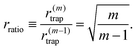 | (7) |
The rate rratio will be used to validate the experimental results.
We remark that the scattering force fscat(rn) with |rn| = r(m)trap acts on the particles trapped in the orbit. Substituting 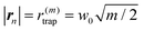 in eqn (4b), we obtain |fscat| = C0A(m), where C0 is a constant independent of m and
 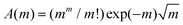 . We can check that A(m) is a monotonically increasing function with respect to m and
 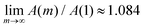 ; that is, |fscat| can be considered to be almost independent from m:
| | | |fscat| ≈ C0A(1), (C0: independent from m). | (8) |
This observation is important because
eqn (8) indicates that
m does not affect the orbital speed. However, the gradient force depends on the azimuthal mode
m. To see this, consider that the particles are trapped near the equilibrium position, meaning |
rn|
≈ r(m)trap, as shown in
Fig. 6. We introduce the trapping stiffness
K = −∂|
fgrad|/∂|
rn| at |
rn| =
r(m)trap, which corresponds to a “spring constant” in the radial direction. Then, it is seen that |
K| =
C1(
mm/
m!)exp(−
m), where
C1 is a constant independent of
m. Since
![[K with combining tilde]](https://www.rsc.org/images/entities/i_char_004b_0303.gif)
(
m) ≡ |
K|/
C1 is a monotonically decreasing function of
m,
e.g.,
(1) = 0.368,
(2) = 0.271,
(3) = 0.224,
(4) = 0.195;
for
m ≫ 1, the optical trapping in the radial direction by the gradient force becomes weaker as
m increases.
Results and discussion
Orbital motion of nano- and microparticles
This section presents an overview of the orbital motion of nano- and microparticles with dp = 0.2, 0.5, 1.0, and 2.0 μm in the test section, as shown in Fig. 3. As will be more closely investigated later, the orbital speed depends on the number of particles N trapped in the orbit. However, it is difficult to count the particles in situ when dp = 0.2 and 0.5 μm owing to their small size and strong thermal fluctuation. Therefore, the results in this section for dp = 0.2 and 0.5 μm are all for a saturated state, in which the entire orbit is occupied by many particles, and for these cases the nanoparticles may not form a single necklace that is seen in Movie S1† for dp = 1 μm. Recall that, in our experiments, the orbit includes a single fluorescent particle and many other non-fluorescent particles, where the fluorescent one is tracked. The fluorescent particle is treated as the representative, and the experimental result of the tracking will be compared with the ensemble average of the simulation results. The OL magnification is 50× for dp = 0.2 μm and 20× for the other cases.
Before going into detail, we remark on the θp-dependence of the dynamics observed in the experiment. The created LG beam intensity has slight inhomogeneity in the azimuthal direction, that is, the imperfection of the optical vortex seems to exist in our experiment. This can be seen from Movie S1:† the orbital speed for the case of N = 8 in the movie seems to be not constant during a single orbiting, i.e., the speed is higher when θp ≈ π/2 than when θp ≈ 3π/2, where the definition of θp is found in Fig. 3(a). However, the effect of θp-dependence can be reduced by considering the time-averaged angular frequency, as discussed in Appendix C with more detailed data analysis on the dynamics during the orbital motion. Therefore, we mainly discuss in this paper the time-averaged orbital speed.
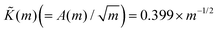
Fig. 4 shows the snapshots of the orbital motion of nano- and microparticles with diameters of 0.2, 0.5, 1.0, and 2.0 μm, using an optical vortex with m = 1. Note that the length of the scale bar is different for dp = 0.2 μm. As shown in Fig. 2, only the excitation light of wavelength 488 nm is used for dp = 0.2 and 0.5 μm, while both the excitation and transmission lights are used for dp = 1.0 and 2.0 μm. The absence of the transmission light for dp = 0.2 and 0.5 μm is to increase the signal-to-noise ratio of the fluorescence intensity of the tracked particle, where the fluorescent particle can only be detected. We see that the particle with dp = 0.2 μm does about half a revolution in 0.40 s, while the particles with dp = 0.5 and 1.0 μm do about one revolution in 0.40 s. The particle with dp = 2.0 μm is the fastest and completes about one and a half revolutions in 0.20 s. In the ESI (Movie S2†), we show that the particle cannot undergo the orbital motion without the microscale confinement.
 |
| | Fig. 4 Snapshots of orbital motion of nano- and microparticles with diameters of (a1)–(a3) 0.2, (b1)–(b3) 0.5, (c1)–(c3) 1.0, and (d1)–(d3) 2.0 μm. The optical vortex with the azimuthal mode m = 1 is used. The laser power Plaser is (a1)–(a3) Plaser = 408, (b1)–(b3) 554, (c1)–(c3) 541, and (d1)–(d3) 532 mW. For dp = 0.2 and 0.5 μm, the transmission light is not used so that we can focus on the motion of a fluorescent particle. Note that the orbits are occupied by invisible non-fluorescent particles. For dp = 1.0 and 2.0 μm, the transmission light for microscopy is also used, and we see that the orbit is occupied by a single fluorescent and multiple non-fluorescent particles. The signal-to-noise ratio is high enough to track the single fluorescent particle for dp = 1.0 and 2.0 μm even under the transmission light. | |
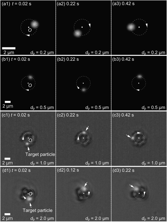
Next, we investigate the orbital characteristics more systematically. The particle tracking is carried out using a video with 50 fps. This frame rate is considered enough to analyze orbital motion with a frequency of O(1) Hz, which is typical of the experimental conditions of this study. To further validate the frame rate, we compare the orbital frequencies obtained with 50 fps and 1000 fps for dp = 0.2 μm, where the thermal fluctuation is the most significant among the cases investigated here. Fig. 5 shows the radial and circumferential positions rp and θp as a function of time for a laser power Plaser = 313 mW and azimuthal mode m = 1. The linear-fit curves agree very well for 50 fps and 1000 fps. The rotational frequency ω, which is the slope of the linear fits, is computed for both cases to compare them quantitatively. We obtain ω = 2.68 × 10⁻¹ Hz for both 50 fps and 1000 fps, and the deviation is less than 0.4%. For the radial direction, the difference in variance σr2 of the resulting position distribution for 50 Hz and 1000 Hz is less than 4%. Therefore, we conclude that a frame rate of 50 fps is enough to analyze orbital motion with thermal fluctuation.
 |
| | Fig. 5 Radial and circumferential positions rp and θp of a trapped particle with dp = 0.2 μm as a function of time. The laser power is set to be 313 mW and the azimuthal mode to m = 1. The straight lines are the fits to the raw data. The data for 1000 fps are shown with gray lines. The effect of the frame rate used in analyzing orbital motion is not significant because two data for 50 fps and 1000 fps agree with a deviation less than 0.4%. | |
In the following, the azimuthal mode is set to be m = 1 for dp = 0.2 μm and m = 1, 3, 5, and 7 for dp ≥ 0.5 μm. It is difficult for our experimental apparatus to trap a particle with dp = 0.2 μm and m ≥ 2 because of the strong thermal fluctuation and weak optical gradient force. Stronger thermal fluctuation for smaller dp can be seen theoretically from eqn (4e), which leads to the situation that the contribution of the random force to the velocity, nnfrand, is proportional to ap−1/2. A weaker optical gradient force for a smaller dp is theoretically predicted as discussed previously below eqn (8). Therefore, the results for dp = 0.2 and dp ≥ 0.5 μm are next presented separately.
(i) Case of d
p
= 0.2 μm
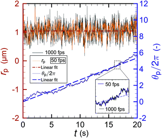
Fig. 6 shows the result of particle tracking for dp = 0.2 μm and Plaser = (a) 408, (b) 367, (c) 313, (d) 295, (e) 223, and (f) 148 mW. The left (red) axis is the distance rp from the beam center and the right (blue) axis the circumferential coordinate θp. The particles undergo thermal fluctuation near an equilibrium position around rp ≈ 1 μm. Note that we are considering a Brownian particle under an external optical force, and thus its motion is different from ordinary diffusion in a free solution, where the diffusion coefficient D can be described as D = σr2/(2t). The data for Plaser = 223 and 148 mW in Fig. 6(e) and (f), respectively, terminate at t ≈ 18 s and 5 s because the trapped particles escape at these times owing to insufficient optical power to overcome the thermal fluctuation. We see from the figure that rp is fluctuating but constant on average in time, and θp linearly increases with time as long as the particle is trapped. Therefore, we treat rp as the radius rtrap of the orbit of trapped particles. The details of the radial force balance will be discussed in the next paragraph. We conclude that the nanoparticle with the diameter of 0.2 μm, which is much smaller than that previously reported,4–12 is driven to stable orbital motion by the optical vortex. The angular frequency for Plaser = 408 mW is ω = 3.31 rad s−1. This success of nanoparticle optical trapping and orbiting is due to the hydrodynamic inter-particle interaction, as will be described later with the simulation results. Fig. 6(g) shows the circumferential force fθ, obtained using eqn (3), acting on the particles for various laser powers. If the optical force is sufficiently larger than the magnitude of the thermal fluctuation, fθ is expected to be proportional to Plaser. Although Fig. 6 does not clearly show a linear relationship between fθ and Plaser owing to the strong thermal fluctuation, it does show that fθ increases with Plaser. One may think a larger Plaser would lead to the data with a higher signal-to-noise-ratio. However, the use of larger Plaser than those presented in this paper may break the microfluidic channel, possibly because of the temperature increase of the PDMS block, and thus, is avoided.
 |
| | Fig. 6 Time development of the orbital radius rp and circumferential coordinate θp for a nanoparticle with diameter dp = 0.2 μm with laser powers of (a) 408, (b) 367, (c) 313, (d) 295, (e) 223, and (f) 148 mW, where the azimuthal mode is set to be m = 1. (g) Circumferential force fθ obtained using eqn (3) and the data of panels (a)–(f) for those laser powers. The value of vθ is also given in panel (g) as a reference. | |
We estimate the trapping stiffness K as follows. If we use a typical parameter set in the experiment such as m = 1, dp = 0.2 μm, Plaser = 313 mW, and rtrap = 1.07 μm, the trapping stiffness K is obtained both experimentally and theoretically as O(10−7) N m−1 with a single significant digit. Here, K in the experiment is obtained using the law of energy equipartition: Kσr2/2 = kBT/2, where σr2 is the variance of the radial position distribution around equilibrium. However, theory yields about triple this value of K, maybe owing to the thermal fluctuation. The thermal fluctuation gives the particles the chance to escape the trap, which softens the effect of the trapping potential. The experimental and theoretical values of the trapping stiffness estimated using the above simple approximation agree well. To validate the treatment of rp ≈ rtrap, rp = rtrap + Δrtrap is considered in a mechanically strict manner, where Δrtrap is a displacement that should satisfy the equation |fgrad(|rn| = rtrap + Δrtrap)| = fcent(= mprpω2) and the force is the origin of realizing the orbital motion. Using experimentally obtained values of fcent = 5.12 × 10⁻²³ N, Δrtrap must be O(10−16) m for the present order of K. Therefore, Δrtrap can be negligible and is not detectable in the present measuring system mainly due to the spatial resolution of image acquisition and thermal fluctuation. Although the theory may have limitations due to the complexity of phenomena, the detailed mechanics can be clarified. It is also confirmed that the trapping effect represented by K certainly governs the stable orbital motion of nanoparticles.
Furthermore, to quantify the effect of thermal fluctuation, we use the experimental displacement distribution to estimate the diffusion coefficient in the radial and circumferential directions for 50 fps and 1000 fps with Plaser = 313 mW. If we assume Wiener diffusion, the displacement forms a Gaussian distribution, and therefore the diffusion coefficient is evaluated by dividing the ensemble average of the mean square displacement by the sampling interval. The mean square displacement is equivalent to the variance of the displacement distribution. We obtain a radial diffusion coefficient of Dr = 1.05 × 10⁻¹² m2 s−1 for 50 fps and Dr = 3.51 × 10⁻¹² m2 s−1 for 1000 fps. One may think that the diffusion coefficient in the radial direction is affected by the presence of the optical force. This point will be discussed later in this paragraph. Using the same procedure, we obtain a circumferential diffusion coefficient of Dθ = 1.90 × 10⁻¹² m2 s−1 for 50 fps and Dθ = 4.00 × 10⁻¹² m2 s−1 for 1000 fps. The reason why the diffusion coefficients are underestimated for 50 fps is as follows. On the basis of the overdamped Langevin equation,53 the characteristic time of a phenomenon is τ0 = ξ/K ≈ 10 ms, where K = 2.42 × 10⁻⁷ N m−1 is the trapping stiffness theoretically obtained as described above. Note that τ0 is the time in which a nanoparticle is accelerated by the optical force. In other words, the particle reflected by an optical potential barrier does not collide with the other barrier at least during τ0 in the case of overdamping. The time resolution for 1000 fps is 1 ms (<τ0), and thus the nanoparticle may diffuse freely during the time interval of 1 ms if the optical force is much weaker than the random force. Therefore, it is reasonable to estimate the diffusion coefficient using the overdamped regime in free solutions for the case of 1000 fps. This is the reason why we can evaluate Dr even under the confining optical force in the radial direction. However, the time resolution for 50 fps is 20 ms (>τ0), and the diffusion coefficient is possibly affected by the optical force. Thus, we suspect that the high frame rate of 1000 fps is better for obtaining a correct diffusion coefficient upon further consideration based on molecular fluid dynamics.54 In fact, it was reported that the diffusion coefficient obtained from the displacement distribution under an external force was underestimated for data acquired with a large frame interval,55 where the external force acting on a particle was caused by the confining particle–wall interaction of two parallel walls. The values of Dr and Dθ for 1000 fps slightly overestimate the diffusion coefficient obtained via the Stokes–Einstein relationship D = kBT/(6πapη) = 2.59 × 10⁻¹² m2 s−1, which may be because the other particles in the orbit enhance the self-diffusion.56 However, the results show that the particle diffusivity in these experimental conditions is similar to that in bulk solutions. We conclude that the diffusion coefficient may be roughly estimated from the displacement distribution even when the Brownian particle is under an optical external force and has motion characteristics different from those of ordinary diffusion.
(ii) Case of d
p
≥ 0.5 μm
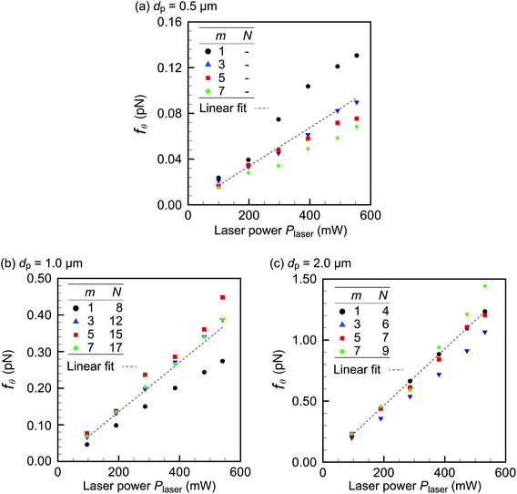
For dp ≥ 0.5 μm, fθ clearly correlates with Plaser linearly because the orbital motion under the optical force is stronger than the thermal fluctuation. Fig. 7 shows the results for the larger diameters 0.5, 1.0, and 2.0 μm for the azimuthal modes (a) m = 1, (b) m = 3, (c) m = 5, and (d) m = 7. The number of particles in the orbit, N, is also indicated in the figure for dp = 1.0 and 2.0 μm. We have chosen N so that the line density ρL along the orbit has similar values for different modes: that is, ρL ≡ 2πrtrap/dp ≈ 0.64 ± 0.03. In these figures, the circumferential force fθ obtained using eqn (3) is plotted for various laser powers. First, we find that fθ linearly correlates with Plaser for all m, as expected from eqn (4b) and (6). As dp increases, fθ also increases owing to the larger scattering cross section. In contrast, the figure does not show a clear dependence of fθ on the mode m. Therefore, we rearrange the data in Fig. 7 for each dp in Fig. 8, which shows fθ for (a) dp = 0.5, (b) 1.0, and (c) 2.0 μm for various azimuthal modes. Fig. 8 shows no clear qualitative m-dependence, and thus the linear-fit lines are drawn using the data for all the m cases. More specifically, in the case of dp = 0.5 μm (panel (a)), fθ tends to be larger for m = 1 but fθ takes similar values for m = 3, 5, and 7; in the case of dp = 1.0 μm (panel (b)), fθ tends to be smaller for m = 1 but fθ takes similar values for m = 3, 5, and 7; in the case of dp = 2.0 μm (panel (c)), fθ takes similar values for m = 1, 3, 5, and 7. The absence of clear m-dependence is due to the fact that |fscat| is almost independent of m in eqn (8). However, one may think that the experiment shown in Fig. 8 is not well controlled, because m = 1 has the highest fθ value for dp = 0.5 μm (panel (a)) and the lowest value for dp = 1.0 μm (panel(b)). This quantitative inconsistency may be due to the fact that fθ is a function of N. For dp = 1.0 μm, we will show more quantitatively that the lower fθ for m = 1 than for m = 3, 5, and 7 in Fig. 8(b) is due to the N-dependence of fθ by comparing the experimental results with simulation.
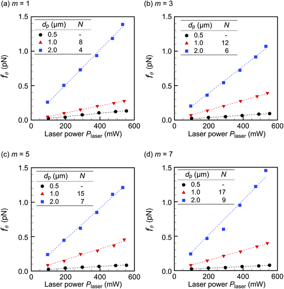 |
| | Fig. 7 Laser power dependence of the circumferential force component fθ for azimuthal modes (a) m = 1, (b) m = 3, (c) m = 5, and (d) m = 7. The cases of dp = 0.5, 1.0, and 2.0 μm are shown. The number of particles N trapped in the orbit is also presented for dp = 1.0 and 2.0 μm. | |
 |
| | Fig. 8 Laser power dependence of the circumferential force component fθ for particle diameters (a) 0.5, (b) 1.0, and (c) 2.0 μm. The cases of m = 1, 3, 5, and 7 are shown. The measured number of particles N trapped in the orbit is also presented for dp = 1.0 and 2.0 μm. | |
Azimuthal-mode dependence on orbital radius
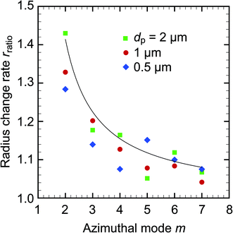
In this section, the effect of m on the orbital radius rtrap is investigated and compared with the simple model of eqn (7). This is important because predicting rtrap contributes to the optimal design of microfluidic channels to use orbital particle motion. Fig. 9 shows the relationship between the radius change rate rratio defined in eqn (7) and the azimuthal mode m for dp = 0.5, 1.0, and 2.0 μm. Eqn (7) well approximates the experimental results quantitatively. Although the particles with dp ≥ 0.5 μm cannot be considered as a part of the Rayleigh regime, the Rayleigh estimation well predicts the orbital radius rtrap. A previous study52 also found that Rayleigh theory made good predictions of gradient force on particles out of its applicable diameter range. Therefore, we conclude that our method of predicting rtrap is a useful first approximation of the orbital radius for engineering applications.
 |
| | Fig. 9 Relationship between the radius change rate rratio in eqn (7) and the azimuthal mode m for dp = 0.5, 1.0, and 2.0 μm. The solid curve represents eqn (7), which is obtained with the Rayleigh approximation. | |
Dependence of the orbital speed on the number of particles
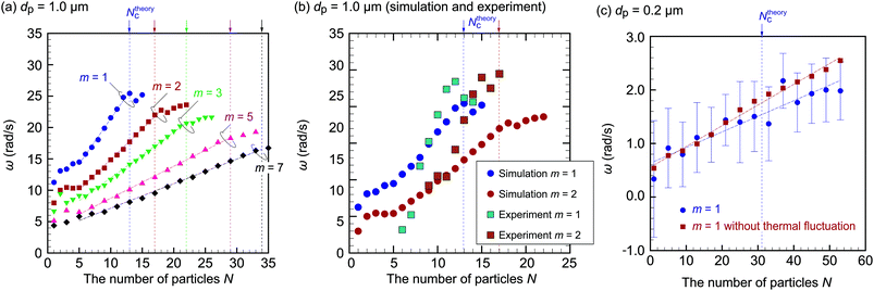
In this section, we investigate the dependence of the orbital motion on the number of particles N, focusing on the cases of dp = 0.2 and 1.0 μm. As discussed for Fig. 7 and 8, we speculate that there is a correlation between N and orbital speed throughout the experiments. Fig. 10 shows the circumferential force component fθ and the corresponding angular frequency ω ≡ vθ/rtrap for dp = 1.0 μm with (a) m = 1 and (b) m = 2 as functions of N. For smaller N values not shown in the figure, multiple particles do not move smoothly in orbits but do have rhythmic motion, as reported elsewhere,11 or are trapped at a certain θp. A part of raw data is presented in Fig. 13 in Appendix C. Both fθ and ω increase as N increases, meaning the orbital speed increases, up to a critical value Nc = 12 for (a) and 15 for (b); fθ and ω are less affected by N for N ≥ Nc. To investigate the relationship between fθ and particle occupancy in the orbit, we compute Ntheoryc from geometrical considerations. The inset of Fig. 10(a) is the schematic of particles with diameter dp contained in an orbit of radius rtrap, where θm is an angle occupied by a single particle. We obtain Ntheoryc as the integer part of 2π/θm, which leads to Ntheoryc = 13 and 17 for m = 1 and 2, respectively. These values are close to those observed in the experiments. We conclude that the angular frequency ω of orbiting particles increases with N and approaches a constant value as N approaches Nc owing to the geometrical restriction. In this paper, we avoid discussing the cases with a larger number of particles than presented, since the particle configuration becomes complicated for N ≥ Nc, e.g., additional particles may squeeze and deform the filled orbit, or may stick to the outer side of the orbit. Therefore, it is difficult to classify these configurations and investigate them systematically. Further investigation of the configuration of multiple necklace that will appear in the case with N ≫ Nc is left for future study.
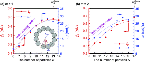 |
| | Fig. 10 Experimental results for fθ and ω as functions of the number of particles N for (a) m = 1 and (b) m = 2 with dp = 1.0 μm. The angle occupied by a single particle, θm, is calculated using rtrap obtained in the experiment: rtrap = 2.10 μm for m = 1 and 2.73 μm for m = 2. Note that the increase of N leads to faster orbiting motion with higher ω. | |
We carry out a numerical simulation based on our model in eqn (1b)–(6) to reveal the origin of the N-dependence of angular frequency observed in the experiments. The parameters in the simulation are similar to those in the experiments: Plaser is set to be 500 mW, and w0 is obtained from the relationship  with rtrap = 2.1 μm, which is obtained experimentally with m = 1 and the OL with a magnification of 20×. In preliminary computations, we find that eqn (4b) overestimates the experimental values of ω by a factor of approximately 10. This overestimation by the simulation may be due to the overestimation of the scattering force and/or the increase of viscosity η in the experiment, which arises because of the wall effect and/or the addition of surfactant. Therefore, we multiply the scattering force by Sc = 0.1 to obtain values of ω that are comparable to the experimental values in Fig. 10. This inconsistency will be closely investigated in future work by including the effects of the wall and surfactant in the model. One may think that Sc should also multiply the gradient force in eqn (4c). However, doing so results in the situation where some particles cannot be kept in the orbit when two or more of them are close to each other. This behavior is not observed in our experiments, and thus multiplying the gradient force by Sc is even qualitatively inconsistent with observation. Therefore, we only multiply the scattering force by Sc. The value Sc = 0.1 is used throughout the paper because it yields moderate agreement between theory and experiment for different particle diameters and azimuthal modes.
Let us describe the result for dp = 1 μm. Fig. 11(a) shows the simulation results for ω, where m = 1, 2, 3, 5, and 7. First, we focus on the profiles for m = 1 and 2, which correspond to the experimental results in Fig. 10(a) and (b), respectively. Fig. 11(b) shows the comparison between the simulation and the experiment. Because we introduced the fitting parameter Sc = 0.1, the experimental values of ω agree well with the simulated values of ≈10–30 rad s−1. The remarkable agreement to be noted is that both the simulation and the experiment show the increase of ω for increasing N up to a critical value N ≤ Nc. Moreover, ω shows a different trend for N > Nc in both the simulation and the experiment: the rate of increase becomes low. Therefore, the N-dependency observed in the experiment in Fig. 10 is well explained qualitatively by our simulation model. However, for more a quantitative comparison, we remark that the effects of the imperfection of the LG beam or of the presence of particles on the electromagnetic field should be carefully taken into account. Because these are extremely difficult problems and complicate the discussion, we leave them for the constitutive investigation in future research and focus mainly on the effect of N in this paper. Given a qualitative agreement between the simulation and experiments, we conclude that the hydrodynamic inter-particle interaction, which becomes strong as N increases, significantly affects the orbital speed. Fig. 11(a) shows that the effect of this hydrodynamic interaction is weaker for higher m. We attribute this to the increase of  for higher m. More precisely, the distance |rnn′| between particles in eqn (2) increases when rtrap increases, leading to lower |fhydrn|.
 |
| | Fig. 11 (a) Simulation results for ω as a function of the number of particles N for m = 1, 2, 3, 5, and 7 with dp = 1.0 μm and Plaser = 500 mW. The orbital frequency ω increases as N increases owing to the hydrodynamic inter-particle interaction. (b) Comparison between the simulation results for m = 1 and 2 in panel (a) and the experimental results in Fig. 10. (c) Simulation results for ω for m = 1 with dp = 0.2 μm, including the results without thermal fluctuation. | |
Next, we compare the resulting fθ values for m = 1, 3, 5, and 7 between the simulation in Fig. 11(a) and the experiment in Fig. 8(b). The goal of this comparison is to understand the m-dependence of fθ in Fig. 8(b). The results are summarized in Table 2, where fθ is normalized by dividing its values for m = 3, 5, and 7 by that for m = 1. The qualitative behavior is consistent between theory and experiment. Therefore, the subtle m-dependence of fθ in Fig. 8(b) is due to the different values of N.
Table 2 Comparison between the experiment (Fig. 8(b)) and simulation (Fig. 11(a)). The force is normalized by dividing the values of fθ for m = 3, 5, and 7 by that for m = 1
| |
m = 1 |
m = 3 |
m = 5 |
m = 7 |
|
N = 8 |
N = 12 |
N = 15 |
N = 17 |
|
Experiment (Fig. 8(b))
|
|
ω (rad s−1) |
16.9 |
14.9 |
14.2 |
10.9 |
|
f
θ
(fN) |
275 |
385 |
450 |
385 |
| Normalized fθ (—) |
1.00 |
1.40 |
1.63 |
1.40 |
|
Simulation (Fig. 11(a))
|
|
ω (rad s−1) |
18.0 |
13.2 |
11.1 |
9.53 |
|
f
θ
(fN) |
291 |
367 |
399 |
406 |
| Normalized fθ (—) |
1.00 |
1.26 |
1.37 |
1.39 |
Finally, Fig. 11(c) presents the simulation result for dp = 0.2 μm. In the experiment, the orbital motion of these particles is the least stable owing to the weak optical force. Recall that the scattering cross sections are σ2 = 8.53 × 10⁻¹ μm2 for dp = 1 μm and σ2 = 4.31 × 10⁻⁴ μm2 for dp = 0.2 μm. The weakness of the scattering force may be why there are no previous studies on dielectric particles with a diameter of 0.2 μm or less. In our experiments, we clearly observe the orbital motion of dielectric particles with dp = 0.2 μm using a microfluidic channel with no biased background fluid flow and a mixture of fluorescent and non-fluorescent particles, as shown in Fig. 4(a1)–(a3) and 6. The corresponding simulation is carried out to show that the hydrodynamic effect on ω is also significant for dp = 0.2 μm. The beam waist w0 is obtained from the relationship  with an experimental value of rtrap = 1.0 μm. Fig. 11(c) shows the relationship between ω and N. The effect of thermal fluctuation is significant for dp = 0.2 μm, and thus ω has larger stochastic fluctuation. Ensemble averages over 10 runs are taken to reduce stochastic noise, and the error bars in Fig. 11(c) show the standard deviation. The results without thermal fluctuation are also plotted for reference in Fig. 11(c), and a little quantitative difference between the plots with and without thermal fluctuation is observed. We find that single-particle orbital motion, N = 1, is difficult to observe because ω is overwhelmed by the thermal fluctuation. As N increases, ω also increases and eventually overcomes the fluctuation, leading to ω ≈ 1.5 rad s−1 at N = Ntheoryc, which means about 0.25 Hz. The experimental value of ω is ω = 3.31 rad s−1, which is on the same order as the simulation value. Therefore, we conclude that the hydrodynamic interaction between particles increases the orbital speed even for dp = 0.2 μm. This is the key to inducing the orbital motion of small dielectric particles.
Contribution of each force component
In this section, we estimate the contributions of forces acting on a single nanoparticle, the nth particle in the orbit. Particularly, we estimate the contributions of the circumferential forces fscatn = |fscat(rn)| and fhydrn = |f![[thin space (1/6-em)]](https://www.rsc.org/images/entities/b_char_2009.gif) hydrn·en,θ| and the radial force fgradn = |fgrad(rn)| in eqn (1b) and (4), using Plaser = 313 mW and dp = 0.2 μm. First, let us consider the radial direction. We take r = rtrap + Δr as the reference position to evaluate the radial component of the optical force fgradn, where Δr = 0.22 μm is the standard deviation from r = rtrap in the experiment. Then, we obtain fgradn = 53.1 fN, which we consider the reference radial component of the optical force. We also compute the potential energy at the reference displacement as (1/2)K(Δr)2 = 5.86 × 10⁻²¹ J, which is comparable to but slightly greater than the thermal fluctuation (1/2)kBT = 2.07 × 10⁻²¹ J. This estimate explains the stable orbital motion for Plaser = 313 mW, as observed in Fig. 6, and the unstable one for the lower laser power of 148 mW in the experiment. However, the circumferential component fscatn acting on a single particle is theoretically estimated as 0.56 fN with Sc = 0.1, which is much lower than the radial component. This may be why it is difficult for a single nanoparticle to undergo orbital motion. We then estimate the simulated hydrodynamic force fhydrn for N = Ntheoryc = 31 and obtain 1.41 fN. The hydrodynamic force is 2.5 times stronger than the scattering force acting on a single particle, and thus the hydrodynamic interaction is dominant in the circumferential direction. The magnitude of repulsive force is about 0.01 fN and negligible. The theoretically estimated circumferential force is thus fθ = fscatn + fhydrn = 1.97 fN, which underestimates the experimentally obtained fθ = 2.92 fN in Fig. 6(g). We speculate that N in the experiment is larger than Nc = 31, leading to a stronger circumferential force in the experiment than in the theory.
hydrn·en,θ| and the radial force fgradn = |fgrad(rn)| in eqn (1b) and (4), using Plaser = 313 mW and dp = 0.2 μm. First, let us consider the radial direction. We take r = rtrap + Δr as the reference position to evaluate the radial component of the optical force fgradn, where Δr = 0.22 μm is the standard deviation from r = rtrap in the experiment. Then, we obtain fgradn = 53.1 fN, which we consider the reference radial component of the optical force. We also compute the potential energy at the reference displacement as (1/2)K(Δr)2 = 5.86 × 10⁻²¹ J, which is comparable to but slightly greater than the thermal fluctuation (1/2)kBT = 2.07 × 10⁻²¹ J. This estimate explains the stable orbital motion for Plaser = 313 mW, as observed in Fig. 6, and the unstable one for the lower laser power of 148 mW in the experiment. However, the circumferential component fscatn acting on a single particle is theoretically estimated as 0.56 fN with Sc = 0.1, which is much lower than the radial component. This may be why it is difficult for a single nanoparticle to undergo orbital motion. We then estimate the simulated hydrodynamic force fhydrn for N = Ntheoryc = 31 and obtain 1.41 fN. The hydrodynamic force is 2.5 times stronger than the scattering force acting on a single particle, and thus the hydrodynamic interaction is dominant in the circumferential direction. The magnitude of repulsive force is about 0.01 fN and negligible. The theoretically estimated circumferential force is thus fθ = fscatn + fhydrn = 1.97 fN, which underestimates the experimentally obtained fθ = 2.92 fN in Fig. 6(g). We speculate that N in the experiment is larger than Nc = 31, leading to a stronger circumferential force in the experiment than in the theory.
The significance of the hydrodynamic effect is explained theoretically as follows. Considering N particles as a single aggregate, as shown in Fig. 12(a) for N = 4, the net circumferential component of optical forces acting on the aggregate is proportional to N. However, the net drag force acting on the aggregate can be analytically obtained as CNfdrag if we approximate the aggregate as a line moving with speed v, as shown in Fig. 12(b).57 We use fdrag = 6πηav as the Stokes drag. The analytical form of CN depends on N and the distance ![[small script l]](https://www.rsc.org/images/entities/i_char_e146.gif) between particles, and is given in the literature for N up to 4.57 More specifically, CN is in the range 1 ≤ CN ≤ N, as shown in Fig. 12(b); that is, the net drag force CNfdrag is less than the superposition of the drag forces acting on N single particles, Nfdrag. Therefore, assuming the linear aggregate in Fig. 12(b), we obtain the analytical form of vθ as v(anal)θ = Nfscatn (CN6πηa)−1. The values of v(anal)θ for = 2a are presented in Fig. 12(c). We carry out the simulation without thermal fluctuation to compare the simulation results with these analytical values. We use a harmonic potential to fix the distances between the particles at ≈ 2a as in the analytical result. Fig. 12(c) also presents the values of the simulated speed v(sim)θ, under the condition /2a < 1.05. We find that v(anal)θ and v(sim)θ agree well, as do their rates of increase with respect to N. Therefore, even though the net optical and drag forces acting on the aggregate both increase with N, the rate of increase for the net optical force overtakes that of the net drag force. The above estimate shows that the hydrodynamic inter-particle interaction is significant in the orbital motion of nanoparticles.
between particles, and is given in the literature for N up to 4.57 More specifically, CN is in the range 1 ≤ CN ≤ N, as shown in Fig. 12(b); that is, the net drag force CNfdrag is less than the superposition of the drag forces acting on N single particles, Nfdrag. Therefore, assuming the linear aggregate in Fig. 12(b), we obtain the analytical form of vθ as v(anal)θ = Nfscatn (CN6πηa)−1. The values of v(anal)θ for = 2a are presented in Fig. 12(c). We carry out the simulation without thermal fluctuation to compare the simulation results with these analytical values. We use a harmonic potential to fix the distances between the particles at ≈ 2a as in the analytical result. Fig. 12(c) also presents the values of the simulated speed v(sim)θ, under the condition /2a < 1.05. We find that v(anal)θ and v(sim)θ agree well, as do their rates of increase with respect to N. Therefore, even though the net optical and drag forces acting on the aggregate both increase with N, the rate of increase for the net optical force overtakes that of the net drag force. The above estimate shows that the hydrodynamic inter-particle interaction is significant in the orbital motion of nanoparticles.
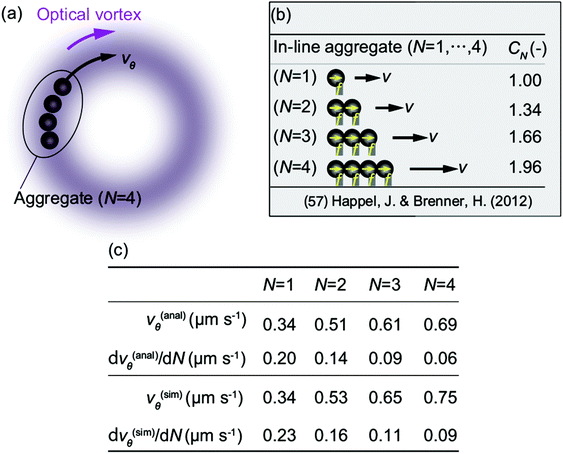 |
| | Fig. 12 Comparison between simulation and analytical results. (a) An N-particle system under the optical vortex is approximated as a single aggregate. The cases up to N = 4 are illustrated. (b) Schematic of a linear aggregate.57 Because dp = 0.2 μm is smaller than the orbital radius rtrap = 1.07 μm, we assume that the aggregate in (a) is approximately linear, as shown in (b). The drag force acting on the linear aggregate is a modified Stokes drag CN(6πηav), where CN is a numeric constant depending on N whose analytical form is given in ref. 57. The analytical form of the velocity v of the linear aggregate is obtained as v = Nf(6πηaCN), where f is an external force acting on each particle. (c) Analytical result vθ(anal) approximated by v = Nf/(6πηaCN) in panel (b) and the simulation result vθ(sim) of panel (a) for N = 1,…4, dp = 0.2 μm, Plaser = 313 mW, and m = 1. The rate of increase, dvθ/dN, obtained with the second-order finite-difference scheme is also given. | |
Concluding remarks
This study has used both experiment and theory to show that hydrodynamic inter-particle interaction increases the orbital speed of nano- and microparticles with diameters from 0.2 to 2.0 μm irradiated by an optical vortex consisting of a focused LG beam with a wavelength of 1064 nm. The experiments achieved stable optical trapping of dielectric nanoparticles even with inherent thermal fluctuation, using the assistance of hydrodynamic inter-particle interaction and microchannel confinement in the direction of laser irradiation. The confinement helps stable trapping by restricting the motion of Brownian particles to two dimensions. Using the radial component of the orbital motion of a trapped particle, we evaluated the optical forces by comparing them with the thermal fluctuation. For the circumferential component, we found both experimentally and theoretically that the orbital speed increased with the number of trapped particles. The diameter of the orbit increased as the azimuthal mode of the optical vortex increased, but the orbital speed was seemed not to be affected by the azimuthal mode when the number density of the particles in the orbit was same. We achieved single-particle tracking in the presence of many other nanoparticles using a mixture of fluorescent and non-fluorescent particles. A theoretical model was developed that included hydrodynamic inter-particle interaction to analyze the experimentally observed behavior of the number of trapped particles, and a micro- and nanofluid dynamics simulation was carried out. The optical force was evaluated from the trapping stiffness in the radial direction. Reasonable agreement was found between the theory and experiment, validating the proposed model. Simulating the model showed qualitatively that the hydrodynamic inter-particle interaction enhances the orbiting speed of micro- and nanoparticles, and the simulation results well explained the number-of-particles dependence and the azimuthal-mode dependence observed in the experiments. These techniques will contribute to the optical manipulation of dielectric micro- and nanoparticles with small polarizability, such as cells and viruses in biosciences. Our future work will apply this technique for controlling nanoparticles in micro- and nanofluidic devices.
Conflicts of interest
There are no conflicts to declare.
Appendix A: fabrication of the silicon mold
An silicon-on-insulator (SOI) wafer (AD004, Sumco Corp., Tokyo, Japan) is used to fabricate the mold for microfluidic devices. The wafer has an SOI layer with a thickness of 3 ± 0.75 μm on the silicon substrate. First, a resist mask is fabricated on the SOI layer using standard photolithography. Then, we carry out deep reactive-ion-etching (RIE) of the SOI layer to fabricate a channel pattern on the silicon substrate. The RIE depth is determined by the thickness of the SOI layer.
The microchannel has contraction parts with a length scale of 3 μm. These contraction parts are prepared to increase the hydraulic resistance Rh over the channel and to increase the flow control resolution. Note that the unexpected flow speed u in the x-direction in the channel is proportional to ΔP/Rh, where ΔP is the pressure difference. Therefore, higher Rh is preferred to achieve lower u. In our experiments, u should be as low as possible to eliminate the effect of the mean flow on the orbiting motion of particles.
The mold has a micrometer-scale pattern with an aspect ratio approximately equal to unity. It is difficult to demold a cured PDMS block with such a fine mold structure because the PDMS sticks to the fine mold pattern and breaks during demolding. To avoid the sticking of the PDMS to the fine pattern, the mold is covered with a self-assembled monolayer (SAM) of 1H,1H,2H,2H-perfluorodecyltriethoxysilane. The process of SAM coating is as follows. First, the mold is carefully cleaned using ultra-sonication in acetone and 2-propanol for 3 minutes. Then, the mold is baked at 120 °C to remove the residual organic solvents. The mold is exposed to ultraviolet light (PL16, Sen Light Corp., Osaka, Japan) for 10 minutes for further cleaning. The cleaned mold is put in a perfluoroalkoxy alkane (PFA) container. In this container we also put a smaller PFA container including a few drops of 1H,1H,2H,2H-perfluorodecyltriethoxysilane solution. After tightly closing the larger PFA container, we put it in an oven (Do-300, RB Technology, Fukuoka, Japan) and heat it at 120 °C for 3 hours. The evaporated solution forms the SAM layer on the mold. The presence of the SAM layer, which is highly hydrophobic, is verified using the droplet method. The contact angle of a water droplet on the mold is improved from 66° before treatment to 106° after treatment, and the formation of the SAM layer is confirmed. Now, we can safely demold the PDMS without breaking the fine pattern.
Appendix B: confirmation of Stokes drag on an orbiting particle
Let us suppose that the center of a sphere is orbiting with a circumferential speed vθ = rtrapω, where ω is the angular frequency. The outer part of the sphere, r = rtrap + dp/2, experiences relative flow vθrel = (rtrap + dp/2)ω − vθ = (dp/2)ω. Therefore, we can approximate the drag acting on the orbiting sphere as that on a sphere placed in a shear flow with a non-dimensional shear rate κ = vrelθ/vθ. The experimental results show that the shear rate is κ = (dp/2)/rtrap = O(1). The correction to the Stokes drag, including lift force, due to the shear rate κ is  ,58 where Re in this study is O(10−7). Therefore, the correction to the Stokes drag is 0.1% at most, and we can safely use Stokes flow dynamics for this study.
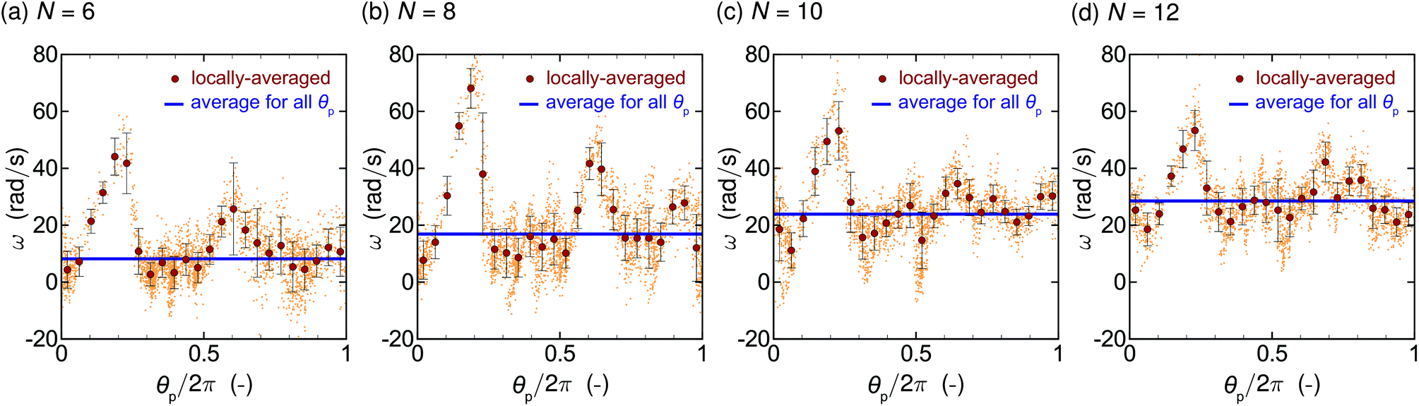
Appendix C: θp dependence of the angular frequency
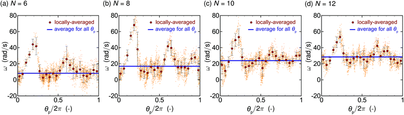
The θp-dependence of the orbital angular frequency ω for the data of Movie S1† and Fig. 10(a) are given in Fig. 13. In Fig. 13, the number of particles in the orbit is set to be (a) N = 6, (b) 8, (c) 10, and (d) 12. The laser power Plaser = 541 mW and the azimuthal mode m = 1 are used. Locally averaged data (large red symbol) are obtained by averaging the raw data of ω (small symbol) in an interval of width Δθp = 2π/25, and the error bars represent the standard deviation. Blue-bold solid lines show the average for all raw data. Standard deviations σdev of the locally averaged data from the mean value are evaluated as (a) σdev = 11.2, (b) 15.2, (c) 9.75, and (d) 8.27 rad s−1. It is seen that ω depends on θp and takes large values around θp/2π ≈ 0.2 for all N, which may be attributed to the imperfection of the ring. The averaged quantities (blue-bold solid lines), which are used in the main text, show the clear increase as the number of particles N.
 |
| | Fig. 13
θ
p-Dependence of the orbital angular frequency ω for the particle with the diameter dp = 1 μm and for the number of particles in the orbit (a) N = 6, (b) 8, (c) 10, and (d) 12. The laser power Plaser = 541 mW and the azimuthal mode m = 1 are used. Locally averaged data (large red symbol) are obtained by averaging the raw data of ω (small symbol) in an interval of width Δθp = 2π/25, and the error bars represent the standard deviation. Blue-bold solid lines show the average for all raw data. The averaged quantities (blue-bold solid lines), which are used in the main text, show the clear increase as the number of particle N. | |
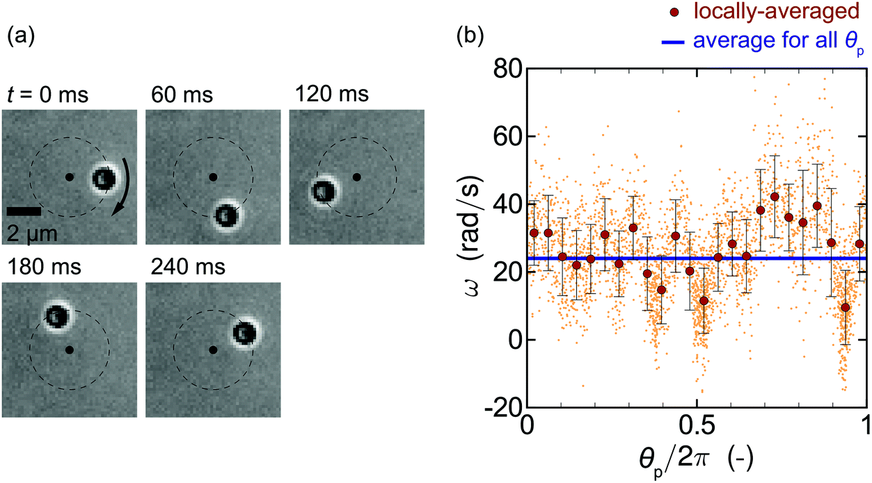
The θp-dependence may be caused by the characteristics of our optical system, but also may be due to the effects of the presence of charged particles and induced solvent flow on the electromagnetic field. These are extremely difficult problems and beyond the scope of the present paper, we leave them for constitutive investigation in future research. Nonetheless, we carry out a similar experiment using a different objective lens with a higher NA value (NA = 1.4, 40× magnification, oil immersion, UPLXAPO40XO, Olympus) to see whether the θp-dependence can be reduced in a different optical setup. The result is given in Fig. 14, where the panel (a) shows the snapshots of the orbital motion using the parameters Plaser = 93 mW, m = 7, and dp = 1 μm with N = 1. It is seen that the single particle orbiting is observed, and Fig. 14(b) presents the θp-dependence of the orbital angular frequency ω for Fig. 14(a). The standard deviation σdev of the locally averaged data from the mean value is σdev = 8.26 rad s−1 and is smaller than those in Fig. 13. However, the complete elimination of the θp-dependence is difficult in the present experimental setup. Therefore, we discuss the averaged quantities (blue-bold solid lines) in the main text.
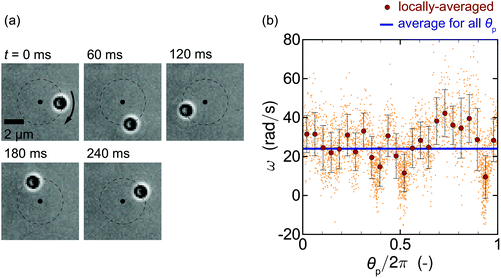 |
| | Fig. 14 (a) Orbital motion of a single particle obtained with a different objective lens with higher NA value (NA = 1.4, 40× magnification, oil immersion, UPLXAPO40XO, Olympus) using parameters Plaser = 93 mW, m = 7, and dp = 1 μm. (b) θp-Dependence of the orbital angular frequency ω. | |
Acknowledgements
This study was supported by the Japan Society for the Promotion of Science (JSPS) KAKENHI under Grant Number JP18H05242 for Scientific Research (S), Grant Number JP16H06504 for Scientific Research on Innovative Areas (Nano-Material Optical-Manipulation), and Grant Number JP18K13687 for Young Scientists; and the Frontier Photonic Sciences Project of the National Institutes of Natural Sciences under Grant Number 01211901.
References
- L. Allen, M. Beijersbergen, R. Spreeuw and J. Woerdman, Orbital angular momentum of light and the transformation of Laguerre-Gaussian laser modes, Phys. Rev. A, 1992, 45, 8185 CrossRef PubMed.
- S. Barnett and L. Allen, Orbital angular momentum and nonparaxial light beams, Opt. Commun., 1994, 110, 670–678 CrossRef.
- J. Courtial, K. Dholakia, L. Allen and M. Padgett, Gaussian beams with very high orbital angular momentum, Opt. Commun., 1997, 144, 210–213 CrossRef CAS.
- J. Curtis and D. Grier, Structure of optical vortices, Phys. Rev. Lett., 2003, 90, 133901 CrossRef PubMed.
- S. Tao, X. Yuan, J. Lin, X. Peng and H. Niu, Fractional optical vortex beam induced rotation of particles, Opt. Express, 2005, 13, 7726–7731 CrossRef CAS PubMed.
- Y. Roichman, D. G. Grier and G. Zaslavsky, Anomalous collective dynamics in optically driven colloidal rings, Phys. Rev. E, 2007, 75, 020401 CrossRef PubMed.
- Y. Sokolov, D. Frydel, D. G. Grier, H. Diamant and Y. Roichman, Hydrodynamic pair attractions between driven colloidal particles, Phys. Rev. Lett., 2011, 107, 158302 CrossRef.
- Y. Sassa, S. Shibata, Y. Iwashita and Y. Kimura, Hydrodynamically induced rhythmic motion of optically driven colloidal particles on a ring, Phys. Rev. E, 2012, 85, 061402 CrossRef PubMed.
- H. Nagar and Y. Roichman, Collective excitations of hydrodynamically coupled driven colloidal particles, Phys. Rev. E, 2014, 90, 042302 CrossRef PubMed.
- S. Okubo, S. Shibata, Y. S. Kawamura, M. Ichikawa and Y. Kimura, Dynamic clustering of driven colloidal particles on a circular path, Phys. Rev. E, 2015, 92, 032303 CrossRef PubMed.
- Y. Kimura, Hydrodynamically induced collective motion of optically driven colloidal particles on a circular path, J. Phys. Soc. Jpn., 2017, 86, 101003 CrossRef.
- K. Saito, S. Okubo and Y. Kimura, Change in collective motion of colloidal particles driven by an optical vortex with driving force and spatial confinement, Soft Matter, 2018, 14, 6037–6042 RSC.
- H. He, M. Friese, N. Heckenberg and H. Rubinsztein-Dunlop, Direct observation of transfer of angular momentum to absorptive particles from a laser beam with a phase singularity, Phys. Rev. Lett., 1995, 75, 826 CrossRef CAS PubMed.
- A. T. O'neil and M. J. Padgett, Three-dimensional optical confinement of micron-sized metal particles and the decoupling of the spin and orbital angular momentum within an optical spanner, Opt. Commun., 2000, 185, 139–143 CrossRef.
- A. O'neil, I. MacVicar, L. Allen and M. Padgett, Intrinsic and extrinsic nature of the orbital angular momentum of a light beam, Phys. Rev. Lett., 2002, 88, 053601 CrossRef PubMed.
- M. Dienerowitz, M. Mazilu, P. J. Reece, T. F. Krauss and K. Dholakia, Optical vortex trap for resonant confinement of metal nanoparticles, Opt. Express, 2008, 16, 4991–4999 CrossRef PubMed.
- P. Figliozzi, N. Sule, Z. Yan, Y. Bao, S. Burov, S. K. Gray, S. A. Rice, S. Vaikuntanathan and N. F. Scherer, Driven optical matter: Dynamics of electrodynamically coupled nanoparticles in an optical ring vortex, Phys. Rev. E, 2017, 95, 022604 CrossRef PubMed.
- K. Gahagan and G. Swartzlander, Optical vortex trapping of particles, Opt. Lett., 1996, 21, 827–829 CrossRef CAS PubMed.
- V. Garcés-Chávez, K. Volke-Sepulveda, S. Chávez-Cerda, W. Sibbett and K. Dholakia, Transfer of orbital angular momentum to an optically trapped low-index particle, Phys. Rev. A, 2002, 66, 063402 CrossRef.
- M. Reichert and H. Stark, Circling particles and drafting in optical vortices, J. Phys.: Condens. Matter, 2004, 16, S4085 CrossRef CAS.
- J. Ng, Z. Lin and C. Chan, Theory of optical trapping by an optical vortex beam, Phys. Rev. Lett., 2010, 104, 103601 CrossRef PubMed.
- M. Tamura, T. Omatsu, S. Tokonami and T. Iida, Interparticle-interaction-mediated anomalous acceleration of nanoparticles under light-field with coupled orbital and spin angular momentum, Nano Lett., 2019, 19, 4873–4878 CrossRef CAS PubMed.
- R. Nagura, T. Tsujimura, T. Tsuji, K. Doi and S. Kawano, Coarse-grained particle dynamics along helical orbit by an optical vortex irradiated in photocurable resins, OSA Continuum, 2019, 2, 400–415 CrossRef CAS.
- J. A. Briggs, K. Grünewald, B. Glass, F. Förster, H.-G. Kräusslich and S. D. Fuller, The mechanism of HIV-1 core assembly: insights from three-dimensional reconstructions of authentic virions, Structure, 2006, 14, 15–20 CrossRef CAS PubMed.
- N. M. Bouvier and P. Palese, The biology of influenza viruses, Vaccine, 2008, 26, D49–D53 CrossRef CAS PubMed.
- K. Toyoda, K. Miyamoto, N. Aoki, R. Morita and T. Omatsu, Using optical vortex to control the chirality of twisted metal nanostructures, Nano Lett., 2012, 12, 3645–3649 CrossRef CAS PubMed.
- F. Takahashi, K. Miyamoto, H. Hidai, K. Yamane, R. Morita and T. Omatsu, Picosecond optical vortex pulse illumination forms a monocrystalline silicon needle, Sci. Rep., 2016, 6, 21738 CrossRef CAS PubMed.
- M. Watabe, G. Juman, K. Miyamoto and T. Omatsu, Light induced conch-shaped relief in an azo-polymer film, Sci. Rep., 2014, 4, 4281 CrossRef PubMed.
- D. Barada, G. Juman, I. Yoshida, K. Miyamoto, S. Kawata, S. Ohno and T. Omatsu, Constructive spin-orbital angular momentum coupling can twist materials to create spiral structures in optical vortex illumination, Appl. Phys. Lett., 2016, 108, 051108 CrossRef.
- J. Lee, Y. Arita, S. Toyoshima, K. Miyamoto, P. Panagiotopoulos, E. M. Wright, K. Dholakia and T. Omatsu, Photopolymerization with light fields possessing orbital angular momentum: generation of helical microfibers, ACS Photonics, 2018, 5, 4156–4163 CrossRef CAS.
- M. Chen, M. Mazilu, Y. Arita, E. M. Wright and K. Dholakia, Dynamics of microparticles trapped in a perfect vortex beam, Opt. Lett., 2013, 38, 4919–4922 CrossRef PubMed.
- M. Chen, M. Mazilu, Y. Arita, E. M. Wright and K. Dholakia, Creating and probing of a perfect vortex in situ with an optically trapped particle, Opt. Rev., 2015, 22, 162–165 CrossRef.
- E. K. Sackmann, A. L. Fulton and D. J. Beebe, The present and future role of microfluidics in biomedical research, Nature, 2014, 507, 181 CrossRef CAS PubMed.
- U. F. Keyser, Controlling molecular transport through nanopores, J. R. Soc., Interface, 2011, 8, 1369–1378 CrossRef CAS PubMed.
- D. G. Grier, A revolution in optical manipulation, Nature, 2003, 424, 810 CrossRef CAS PubMed.
- K. C. Neuman and S. M. Block, Optical trapping, Rev. Sci. Instrum., 2004, 75, 2787–2809 CrossRef CAS.
- T. Sugiyama, K.-i. Yuyama and H. Masuhara, Laser trapping chemistry: from polymer assembly to amino acid crystallization, Acc. Chem. Res., 2012, 45, 1946–1954 CrossRef CAS PubMed.
- O. M. Maragò, P. H. Jones, P. G. Gucciardi, G. Volpe and A. C. Ferrari, Optical trapping and manipulation of nanostructures, Nat. Nanotechnol., 2013, 8, 807 CrossRef PubMed.
- A. Lehmuskero, P. Johansson, H. Rubinsztein-Dunlop, L. Tong and M. Kall, Laser trap ping of colloidal metal nanoparticles, ACS Nano, 2015, 9, 3453–3469 CrossRef CAS PubMed.
- F. Nito, T. Shiozaki, R. Nagura, T. Tsuji, K. Doi, C. Hosokawa and S. Kawano, Quantitative evaluation of optical forces by single particle tracking in slit-like microfluidic channels, J. Phys. Chem. C, 2018, 122, 17963–17975 CrossRef CAS.
- T. Tsuji, Y. Matsumoto and S. Kawano, Flow with nanoparticle clustering controlled by optical forces in quartz glass nanoslits, Microfluid. Nanofluid., 2019, 23, 126 CrossRef.
- A. Ashkin, J. M. Dziedzic, J. Bjorkholm and S. Chu, Observation of a single-beam gradient force optical trap for dielectric particles, Opt. Lett., 1986, 11, 288–290 CrossRef CAS PubMed.
- S. Tanaka, M. Tsutsui, H. Theodore, H. Yuhui, A. Arima, T. Tsuji, K. Doi, S. Kawano, M. Taniguchi and T. Kawai, Tailoring particle translocation via dielectrophoresis in pore channels, Sci. Rep., 2016, 6, 31670 CrossRef CAS PubMed.
- T. Tsuji, K. Kozai, H. Ishino and S. Kawano, Direct observations of thermophoresis in microfluidic systems, Micro Nano Lett., 2017, 12, 520–525 CrossRef CAS.
- T. Tsuji, S. Saita and S. Kawano, Dynamic pattern formation of microparticles in a uniform flow by an on-chip thermophoretic separation device, Phys. Rev. Appl., 2018, 9, 024035 CrossRef CAS.
- T. Tsuji, Y. Sasai and S. Kawano, Thermophoretic manipulation of micro-and nanoparticle flow through a sudden contraction in a microchannel with near-infrared laser irradiation, Phys. Rev. Appl., 2018, 10, 044005 CrossRef CAS.
- L. Lin, J. Zhang, X. Peng, Z. Wu, A. C. Coughlan, Z. Mao, M. A. Bevan and Y. Zheng, Opto-thermophoretic assembly of colloidal matter, Sci. Adv., 2017, 3, e1700458 CrossRef PubMed.
- K. Setoura, T. Tsuji, S. Ito, S. Kawano and H. Miyasaka, Opto-thermophoretic separation and trapping of plasmonic nanoparticles, Nanoscale, 2019, 11, 21093–21102 RSC.
- J. Rotne and S. Prager, Variational treatment of hydrodynamic interaction in polymers, J. Chem. Phys., 1969, 50, 4831–4837 CrossRef CAS.
- H. Yamakawa, Transport properties of polymer chains in dilute solution: hydrodynamic interaction, J. Chem. Phys., 1970, 53, 436–443 CrossRef CAS.
- J. Zhang, S.-J. Huang, F.-Q. Zhu, W. Shao and M.-S. Chen, Dimensional properties of Laguerre–Gaussian vortex beams, Appl. Opt., 2017, 56, 3556–3561 CrossRef PubMed.
- Y. Harada and T. Asakura, Radiation forces on a dielectric sphere in the Rayleigh scattering regime, Opt. Commun., 1996, 124, 529–541 CrossRef CAS.
- W. Qian, K. Doi and S. Kawano, Effects of polymer length and salt concentration on the transport of ssDNA in nanofluidic channels, Biophys. J., 2017, 112, 838–849 CrossRef CAS.
- T. Li, S. Kheifets, D. Medellin and M. G. Raizen, Measurement of the instantaneous velocity of a Brownian particle, Science, 2010, 328, 1673–1675 CrossRef CAS PubMed.
- I. Hanasaki, Y. Kazoe and T. Kitamori, Time resolution effect on the apparent particle dynamics confined in a nanochannel evaluated by the single particle tracking subject to Brownian motion, Microfluid. Nanofluid., 2018, 22, 56 CrossRef.
- K. Zahn, J. M. Méndez-Alcaraz and G. Maret, Hydrodynamic interactions may enhance the self-diffusion of colloidal particles, Phys. Rev. Lett., 1997, 79, 175 CrossRef CAS.
-
J. Happel and H. Brenner, Low Reynolds number hydrodynamics: with special applications to particulate media, Springer Science & Business Media, 2012, vol. 1 Search PubMed.
- D. A. Drew, The force on a small sphere in slow viscous flow, J. Fluid Mech., 1978, 88, 393–400 CrossRef.
Footnotes |
| † Electronic supplementary information (ESI) available. See DOI: 10.1039/C9NR10591C |
| ‡ Present address: Graduate School of Informatics, Kyoto University, Kyoto 606–8501, Japan. |
|
| This journal is © The Royal Society of Chemistry 2020 |
Click here to see how this site uses Cookies. View our privacy policy here. 
 Open Access Article
 This Open Access Article is licensed under a
  *,
Ryoji
Nakatsuka
,
Kichitaro
Nakajima
,
Kentaro
Doi
and
Satoyuki
Kawano
*
*,
Ryoji
Nakatsuka
,
Kichitaro
Nakajima
,
Kentaro
Doi
and
Satoyuki
Kawano
*
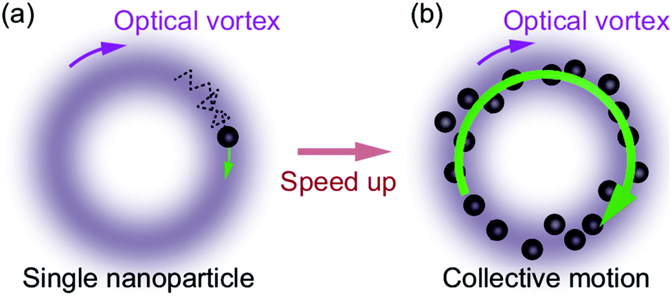
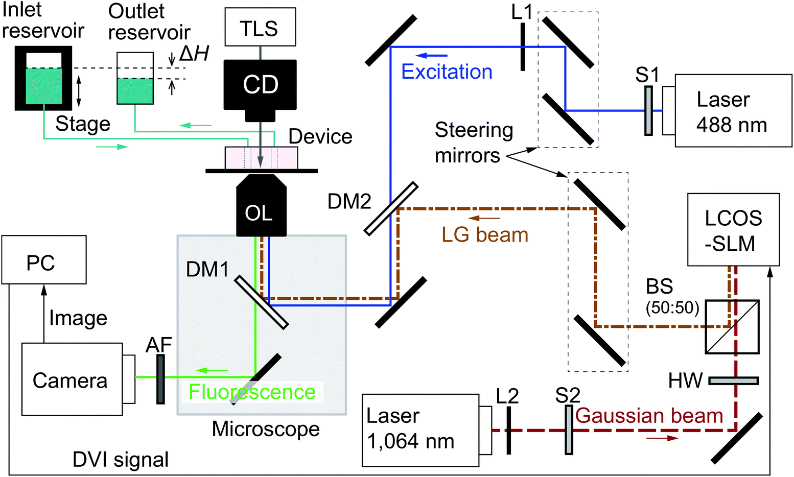
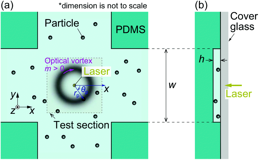

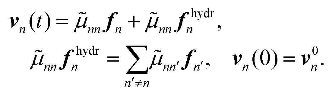
 takes on the values 1, …, n − 1, n + 1, …, N; fn = (fx,n, fy,n) is the force acting on the nth particle other than the drag; r0n and v0n are the initial position and velocity, respectively; and
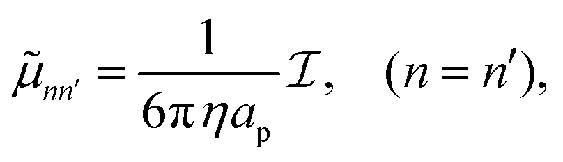
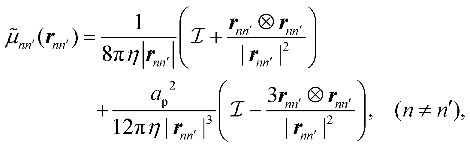
 is the identity matrix. We focus on the circumferential component by taking the dot product of en,θ and eqn (1b); that is, we define fθ and vθ as:
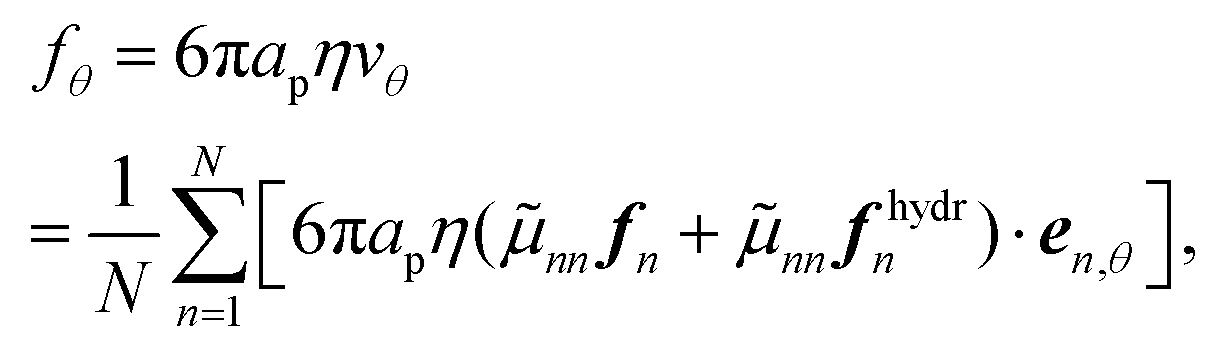
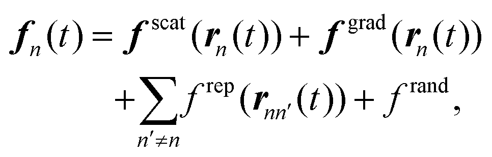
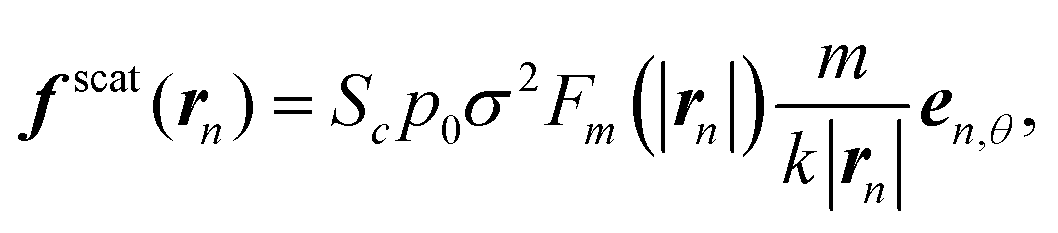


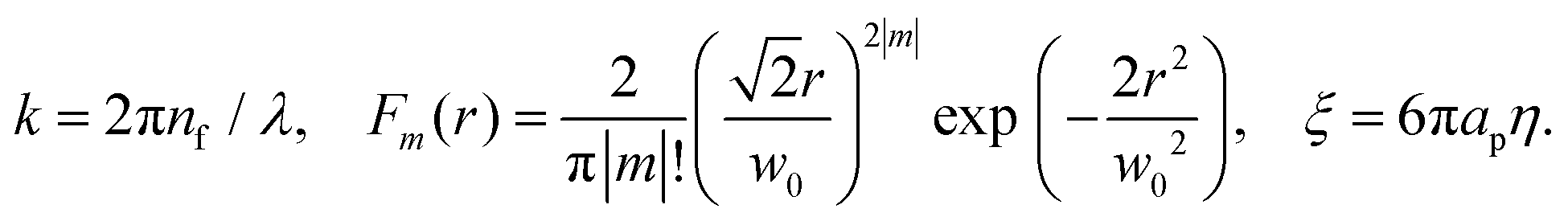
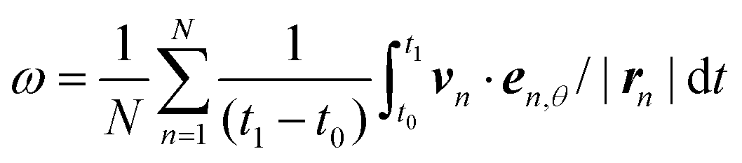 , where t0 = 1 s and t1 = 10 s determine the sampling interval in the simulation. The effect of the initial configuration disappears for t > 1 s. The time step of the simulation is taken to be Δt = 1 × 10⁻⁷ s, and Δt is small enough to avoid Δt-dependence of the results.
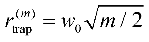 . To eliminate the dependence on w0 for qualitative discussion, we focus on the radius change rate defined as
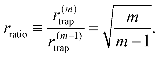
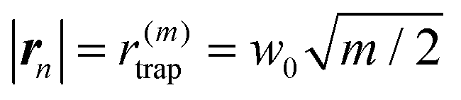 in eqn (4b), we obtain |f
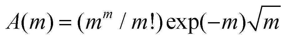 . We can check that A(m) is a monotonically increasing function with respect to m and
 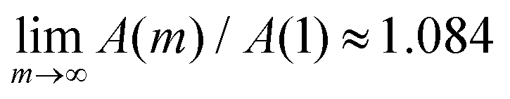 ; that is, |f
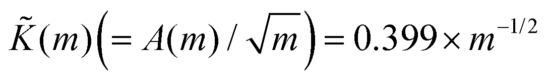 for m ≫ 1, the optical trapping in the radial direction by the gradient force becomes weaker as m increases.
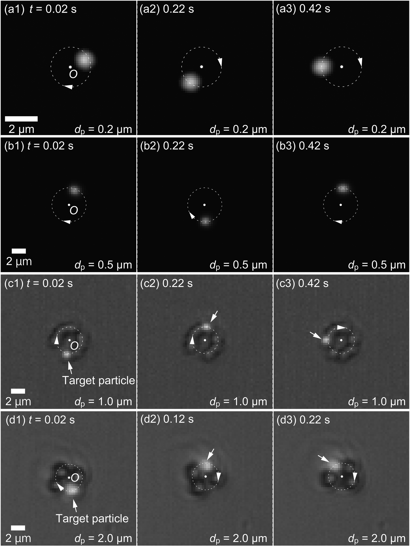

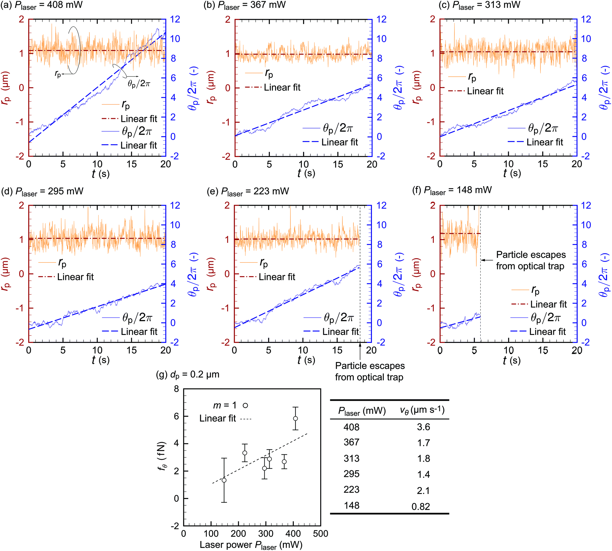


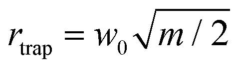 with rtrap = 2.1 μm, which is obtained experimentally with m = 1 and the OL with a magnification of 20×. In preliminary computations, we find that eqn (4b) overestimates the experimental values of ω by a factor of approximately 10. This overestimation by the simulation may be due to the overestimation of the scattering force and/or the increase of viscosity η in the experiment, which arises because of the wall effect and/or the addition of surfactant. Therefore, we multiply the scattering force by Sc = 0.1 to obtain values of ω that are comparable to the experimental values in Fig. 10. This inconsistency will be closely investigated in future work by including the effects of the wall and surfactant in the model. One may think that Sc should also multiply the gradient force in eqn (4c). However, doing so results in the situation where some particles cannot be kept in the orbit when two or more of them are close to each other. This behavior is not observed in our experiments, and thus multiplying the gradient force by Sc is even qualitatively inconsistent with observation. Therefore, we only multiply the scattering force by Sc. The value Sc = 0.1 is used throughout the paper because it yields moderate agreement between theory and experiment for different particle diameters and azimuthal modes.
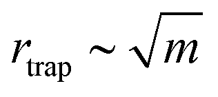 for higher m. More precisely, the distance |rnn′| between particles in eqn (2) increases when rtrap increases, leading to lower |f
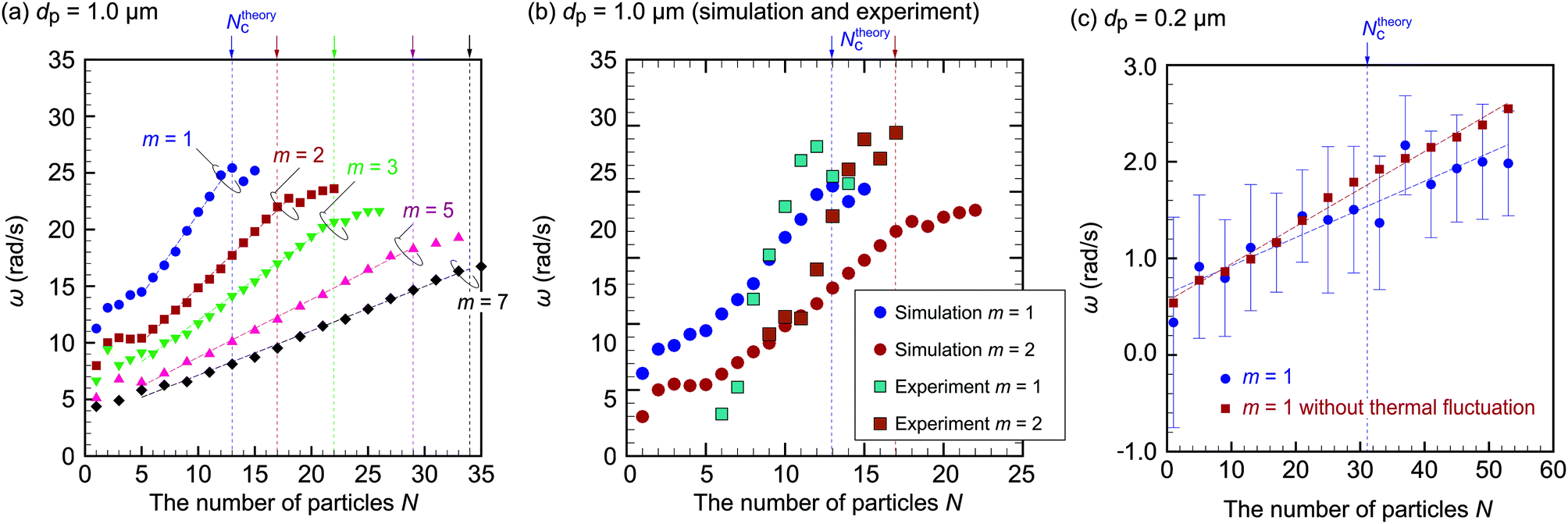
 with an experimental value of rtrap = 1.0 μm. Fig. 11(c) shows the relationship between ω and N. The effect of thermal fluctuation is significant for dp = 0.2 μm, and thus ω has larger stochastic fluctuation. Ensemble averages over 10 runs are taken to reduce stochastic noise, and the error bars in Fig. 11(c) show the standard deviation. The results without thermal fluctuation are also plotted for reference in Fig. 11(c), and a little quantitative difference between the plots with and without thermal fluctuation is observed. We find that single-particle orbital motion, N = 1, is difficult to observe because ω is overwhelmed by the thermal fluctuation. As N increases, ω also increases and eventually overcomes the fluctuation, leading to ω ≈ 1.5 rad s−1 at N = Ntheoryc, which means about 0.25 Hz. The experimental value of ω is ω = 3.31 rad s−1, which is on the same order as the simulation value. Therefore, we conclude that the hydrodynamic interaction between particles increases the orbital speed even for dp = 0.2 μm. This is the key to inducing the orbital motion of small dielectric particles.
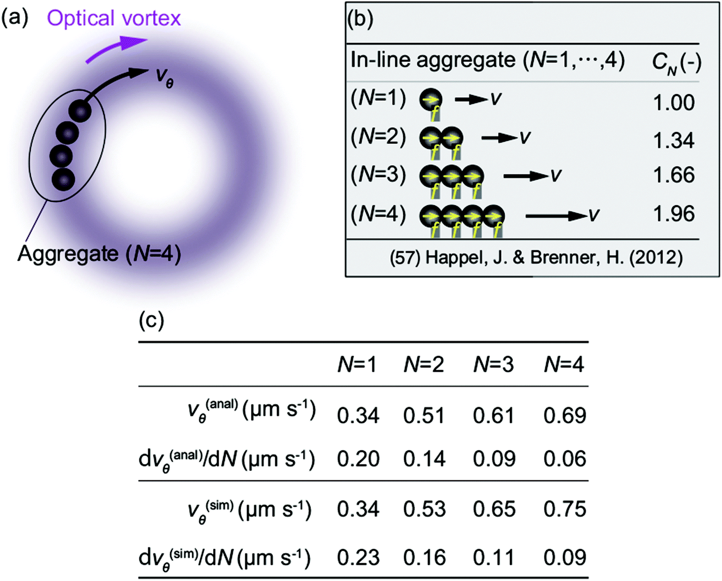
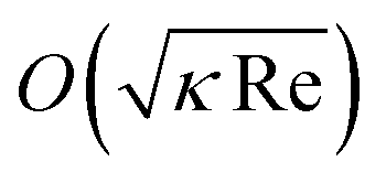 ,58 where Re in this study is O(10−7). Therefore, the correction to the Stokes drag is 0.1% at most, and we can safely use Stokes flow dynamics for this study.