
 Open Access Article
 This Open Access Article is licensed under a Creative Commons Attribution-Non Commercial 3.0 Unported Licence
Nanostructured core–shell metal borides–oxides as highly efficient electrocatalysts for photoelectrochemical water oxidation†
Can
Lu
a,
Palani R.
Jothi
 b,
Thomas
Thersleff
c,
Tetyana M.
Budnyak
c,
Anna
Rokicinska
d,
Kunio
Yubuta
e,
Richard
Dronskowski
af,
Piotr
Kuśtrowski
d,
Boniface P. T.
Fokwa
*b and
Adam
Slabon
*c
b,
Thomas
Thersleff
c,
Tetyana M.
Budnyak
c,
Anna
Rokicinska
d,
Kunio
Yubuta
e,
Richard
Dronskowski
af,
Piotr
Kuśtrowski
d,
Boniface P. T.
Fokwa
*b and
Adam
Slabon
*c
aInstitute of Inorganic Chemistry, RWTH Aachen University, Landoltweg 1, D-52056 Aachen, Germany
bDepartment of Chemistry and Center for Catalysis, University of California, Riverside, 92507 California, USA. E-mail: bfokwa@ucr.edu
cDepartment of Materials and Environmental Chemistry, Stockholm University, Svante Arrhenius väg 16 C, 10691 Stockholm, Sweden. E-mail: adam.slabon@mmk.su.se
dFaculty of Chemistry, Jagiellonian University, Gronostajowa 2, 30-387 Krakow, Poland
eInstitute for Materials Research, Tohoku University, Katahira 2-1-1, Sendai 980-8577, Japan
fHoffmann Institute of Advanced Materials, Shenzhen Polytechnic, Liuxian Blvd 7098, 518055 Shenzhen, China
First published on 13th January 2020
Abstract
Oxygen evolution reaction (OER) catalysts are critical components of photoanodes for photoelectrochemical (PEC) water oxidation. Herein, nanostructured metal boride MB (M = Co, Fe) electrocatalysts, which have been synthesized by a Sn/SnCl2 redox assisted solid-state method, were integrated with WO3 thin films to build heterojunction photoanodes. As-obtained MB modified WO3 photoanodes exhibit enhanced charge carrier transport, amended separation of photogenerated electrons and holes, prolonged hole lifetime and increased charge carrier density. Surface modification of CoB and FeB significantly enhances the photocurrent density of WO3 photoanodes from 0.53 to 0.83 and 0.85 mA cm−2, respectively, in transient chronoamperometry (CA) at 1.23 V vs. RHE (VRHE) under interrupted illumination in 0.1 M Na2SO4 electrolyte (pH 7), corresponding to an increase of 1.6 relative to pristine WO3. In contrast, the pristine MB thin film electrodes do not produce noticeable photocurrent during water oxidation. The metal boride catalysts transform in situ to a core–shell structure with a metal boride core and a metal oxide (MO, M = Co, Fe) surface layer. When coupled to WO3 thin films, the CoB@CoOx nanostructures exhibit a higher catalytic enhancement than corresponding pure cobalt borate (Co-Bi) and cobalt hydroxide (Co(OH)x) electrocatalysts. Our results emphasize the role of the semiconductor–electrocatalyst interface for photoelectrodes and their high dependency on materials combination.
Introduction
Due to the rising global energy demand and corresponding environment concerns becoming a public focus, the production of environment-neutral fuels has been considered highly important.1 Among the potential candidates, hydrogen has emerged to be one of the most promising energy carriers possessing superiorities such as high energy density and abundancy.2,3 PEC water splitting is considered as a sustainable solution to directly produce hydrogen from water using solar fuel.4,5 To date, significant improvement has been achieved for photocathodes; profiting highly from the experiences in industrial semiconductor production technology such as solar cell development.6,7 Nevertheless, water oxidation involving the transfer of four electrons is demanding with respect to kinetics and stability, thus limiting the PEC water-splitting efficiency.8,9 Consequently, it is crucial to develop highly active, stable and low-cost photoanodes to achieve commercialization of PEC technology in the future.A broad variety of n-type semiconductors have been employed as photoabsorbers in photoanode-driven systems, including TiO2,10 BiVO4,11 CuWO4,12 and WO3.13 Due to the low catalytic activity of the semiconductor surface, it is essential to modify the light-absorber with electrocatalysts.11,14 Although this strategy to improve current densities of thin film photoanodes is generally accepted, the influence of the semiconductor–electrocatalyst interface on the PEC OER cannot be predicted directly.15 Only recently, metal boride catalysts have shown excellent electrochemical catalytic performances due to their fast kinetics and superior stability, stemming from the synergistic effect of in situ formed thin oxide, hydroxide or oxyhydroxide layer and boride core.3,16,17 A Ni-B@NiOxH catalyst supported on nickel foam showed for instance 20 mA cm−2 at 0.28 V overpotential in 1.0 M KOH, which surpassed the activity of most previously reported nonprecious electrocatalysts for OER.18 Within the core–shell catalysts, the surface shell functions as catalytic sites while the inner core facilitates charge transfer.16,17,19
However, to the best of our knowledge, there are only two reports on integrating metal borides as catalysts with semiconductors for water oxidation.20,21 Dang et al. deposited NiB on a BiVO4 photoanode to obtain improved charge carrier mobility and pronounced band bending was achieved, which led to a 100 mV cathodic shift of onset potential and boosted the photocurrent density to 3.47 mA cm−2 at 1.23 VRHE, corresponding to 2.2-fold enhancement.20 An in situ fabricated Fe2O3/FeB photoanode by Liao et al. doubled the photocurrent density at 1.23 VRHE relative to the pristine hematite, taking the advantages of ameliorated charge carrier separation and reduced charge transfer resistance.21 These trials revealed the feasibility of utilizing metal borides as effective electrocatalysts to boost the PEC OER.
Conventionally, nanostructured metal boride catalysts are synthesized by the chemical reduction of metal salt precursors with NaBH4.3,22 An additional annealing treatment is usually necessary if crystalline structures need to be obtained.16 From the practical application perspective for this kind of catalysts, more simple, cost-efficient, high-yield synthetic routes are preferred, for amenable mass production while enabling sufficient active sites.
We synthesized nanostructured CoB and FeB by a Sn/SnCl2 redox assisted solid-state method with simple, highly efficient and large-scale amenable advantages.23,24 These CoB nanosheets and FeB nanoplates were evaluated for the first time as PEC water oxidation catalysts to modify hydrothermally grown WO3 thin films on fluorine doped tin oxide (FTO) glass. Mechanistic investigation demonstrated that the augmented water oxidation property originates from the synergetic effects through coupling WO3 with in situ formed core–shell MB@MO.
Experimental
Photoanodes fabrication
The crystalline MB catalysts were prepared by a Sn/SnCl2 redox assisted solid-state method.23 WO3 thin films were hydrothermally grown on FTO substrate followed by additional thermal treatment.25 The MB-modified WO3/MB thin film photoelectrodes were fabricated via drop-casting. For the comparison of the heterojunction WO3/MB photoanodes, we synthesized catalysts such as Co-Bi and Co(OH)x.26,27 These catalysts were deposited identically on WO3 thin film. The exact experimental details are provided in the ESI.†Characterization
The crystal structures of all samples were characterized by a powder X-ray diffractometer (PXRD, STOE STADI-P) with Cu Kα1 radiation in transmission mode. Surface morphology was characterized using a scanning electron microscope (SEM, Leo Supra 35VP SMT, Zeiss). High-resolution transmission electron microscopy (HRTEM) observation and selected area electron diffraction (SAED) characterization were conducted on a 200 kV electron microscope (TOPCON EM-002B). Electron energy-loss spectrum (EELS) was obtained in STEM mode from a Themis Z TEM (Thermo Fisher). The optical properties were characterized using a UV-vis spectrophotometer (UV-2600, Shimadzu). X-ray photoelectron spectroscopy (XPS) spectra were recorded using a hemispherical VG SCIENTA R3000 analyzer with a monochromatized aluminum source Al Kα (E = 1486.6 eV) at constant pass energy of 100 eV. The binding energies were referenced to the Au 4f core level (Eb = 84.0 eV) and the fitting of high-resolution spectra was obtained through the Casa XPS software.Photoelectrochemical measurements
The PEC measurements were conducted in a three-electrode system under simulated Air Mass 1.5 Global solar light irradiation (AM 1.5G, 100 mW cm−2, class-AAA 94023A, Newport) with the fabricated electrodes as the working electrodes, a platinum electrode as the counter electrode and a 1 M Ag/AgCl electrode as reference electrode. All measurements were conducted under back-side illumination and the measured potentials were adjusted to VRHE using the Nernstian relation (ERHE = E0Ag/AgCl + 0.059 V × pH + EAg/AgCl). The electrolyte used was 0.1 M Na2SO4 aqueous solution with or without 50 mM Na2SO3 as holes scavenger (pH ≈ 7).The linear sweep voltammetry (LSV) with a scan rate of 10 mV s−1 and chronoamperometry (CA) at a constant bias of 1.23 VRHE were performed with a potentiostat (PalmSens4, PalmSens BV). The electrochemical impedance spectra (EIS) were recorded under AM 1.5G irradiation in the range of 0.02 Hz to 20 kHz, with an AC voltage amplitude of 5 mV at a DC bias of 1 VRHE. Mott–Schottky characterizations were carried out with an amplitude of 10 mV and frequency of 10 Hz under AM 1.5G illumination. Open circuit voltage (OCV) decay measurements were performed in Ar atmosphere and AM 1.5G light illumination was initiated once the OCV was stabilized in dark.
Results and discussion
Structural characterization
The synthesized WO3 thin film can be assigned to the single, highly crystalline monoclinic phase (JCPDS no. 83-0951) observed in the PXRD patterns (Fig. S1†). The PXRD patterns of CoB and FeB are shown in Fig. S2† and can be indexed to COD data of 9008945 and 9008944, respectively.23 The diffraction peaks show that the boride catalysts are crystalline. The PXRD patterns of the composite photoanodes reveal only the diffraction peaks stemming from the oxidic light absorber, because the catalyst loading was very small (vide infra). Fig. S3† shows the SEM images of bare WO3 film. The film is composed of numerous porous WO3 plates which are nearly perpendicularly aligned to the FTO substrate. Closer inspection reveals each plate to be composed of several primary units of thin WO3 sheets with an average thickness of approximately 180 nm, showing a distinct sandwich-like structure. Representative SEM images of the bare CoB and FeB can be seen in our previous work.23 The CoB is in the form of two-dimensional (2D) nanosheets while the FeB exhibits the feature of nanoplates.Fig. 1a and b show the SEM images of the WO3/CoB and WO3/FeB, respectively. The morphological characteristics remain unaltered after the surface functionalization with MB catalysts, which can be attributed to the low loading content on the surface. The HRTEM images and corresponding SAED patterns confirm the high crystallinity of the bare CoB and FeB catalysts (Fig. 1c–e). Fig. 1f illustrates the corresponding crystal structure of orthorhombic CoB and FeB.
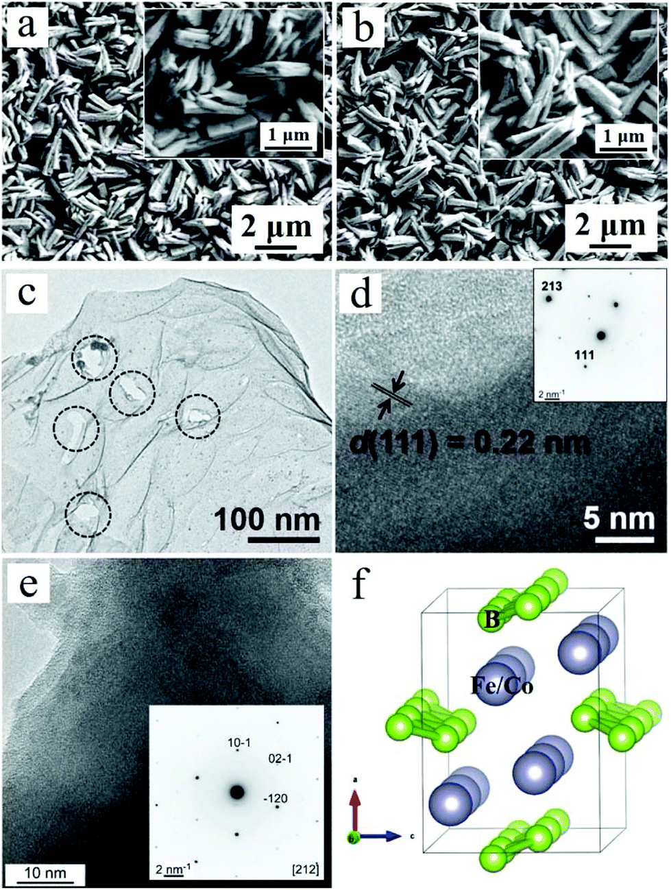 | ||
| Fig. 1 SEM images of (a) WO3/CoB and (b) WO3/FeB. (c) TEM image of pristine CoB. The circles highlight defects in the two-dimensional structure. HRTEM images of CoB (d) and FeB (e) (insets: corresponding SAED patterns). (f) Crystal structure of CoB and FeB. | ||
Photoelectrochemistry
The PEC water oxidation was investigated for bare WO3, WO3/CoB and WO3/FeB photoanodes in 0.1 M Na2SO4 electrolyte (adjusted to pH 7) under interrupted illumination and optimized catalyst loading amount. LSV and CA at 1.23 VRHE are shown in Fig. 2a and b. The complementary PEC water oxidation under constant illumination and optimization of catalyst loading amount are shown Fig. S4, S5 and S6,† respectively. All photoanodes do not exhibit dark current during the LSV, suggesting as such no occurrence of electrochemical reactions in the absence of illumination (Fig. S4†). All photoelectrodes develop an anodic photocurrent under simulated AM 1.5G light illumination. The UV-vis absorption edge of the as-prepared WO3 thin film approaches ca. 460 nm (Fig. S7†), being equivalent to a band gap of 2.75 eV (vide infra). Even so, the pristine WO3 photoanode exhibits an onset potential of ca. 0.7 VRHE and a photocurrent density of 0.70 mA cm−2 at 1.23 VRHE (Fig. 2). This hints toward severe recombination of photogenerated charge carriers.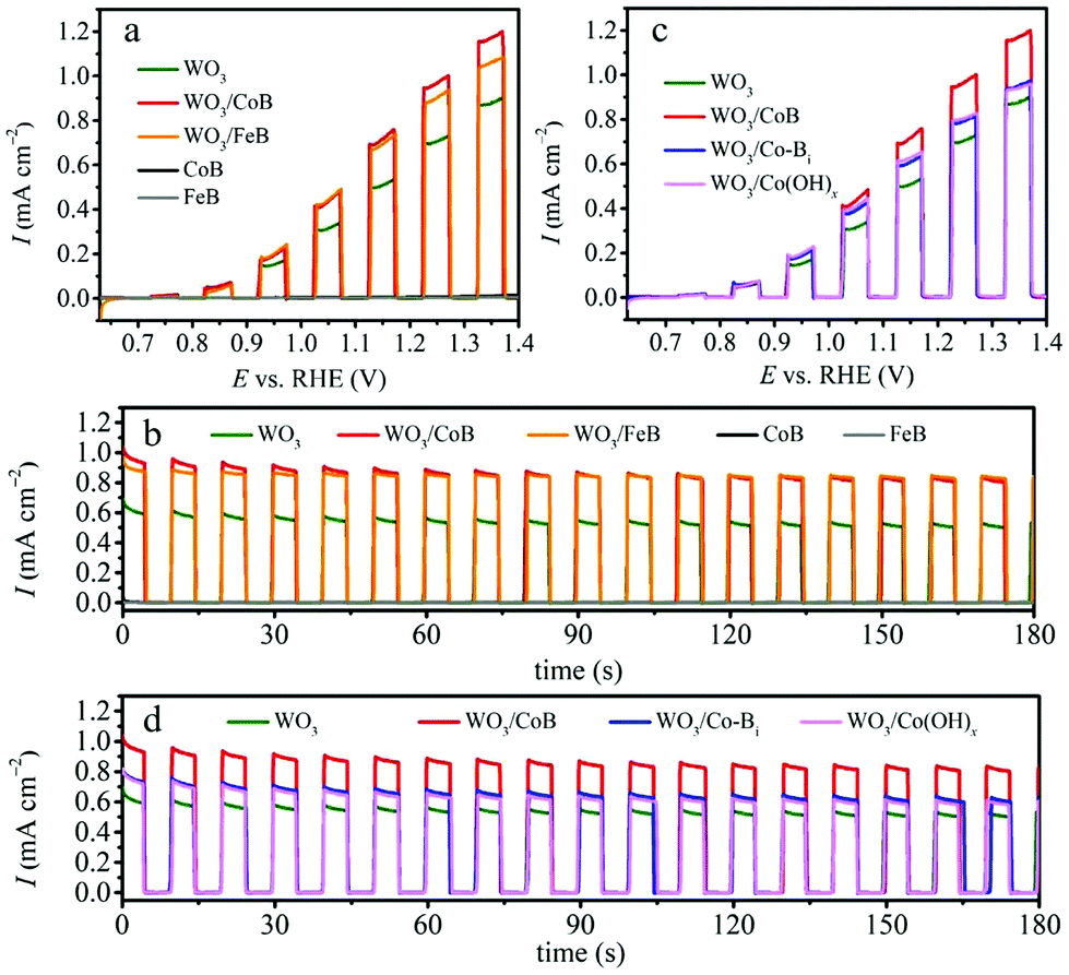 | ||
| Fig. 2 (a) LSV and (b) CA curves of WO3, WO3/CoB and WO3/FeB photoanodes. (c) LSV and (d) CA curves of WO3, WO3/CoB, WO3/Co-Bi and WO3/Co(OH)x photoanodes. All curves were recorded under interrupted AM 1.5G illumination in 0.1 M Na2SO4 electrolyte (pH 7). | ||
Upon the loading of CoB and FeB catalysts, a substantial upsurge of the photocurrent density to 0.95 and 0.89 mA cm−2vs. 1.23 VRHE can be observed, respectively (Fig. 2a). Since the bare CoB and FeB produce negligible current during the LSV, the enhancement of photocurrent for the composite photoanodes stems synergistic effects between the WO3 and MB catalysts. The onset potentials of pristine WO3 and modified photoanodes are all close of 0.7 VRHE; indicating that the conduction band edge, i.e. approximately the flat band potential, remains pinned after surface modification.28,29 This result differs from the previously reported Fe2O3/FeB heterojunction photoanode,21 where the onset potential exhibited a cathodic shift by about 80 mV in comparison to pristine Fe2O3. This difference suggests that the surface modification of above-mentioned MB catalysts highly depends on the substrate materials, coating methods and also surface coverage achieved.29 Transient CA at 1.23 VRHE under interrupted illumination displays more obviously that surface modification of CoB and FeB meaningfully ameliorates the photocurrent density of WO3 photoanode from 0.53 to 0.83 and 0.85 mA cm−2 (Fig. 2b, at 175 s), corresponding to a 1.57 times and 1.60 times enhancement, respectively. More importantly, the photocurrent decay of WO3/FeB photoanode is effectively mitigated relative to the pristine one, demonstrating that the loading of the FeB catalyst can reduce the hole accumulation by accelerating the oxidation of H2O to O2.28–30
To give further perspective on our MB catalysts, the performance of CoB was compared against Co-Bi and Co(OH)x, with optimized amounts (Fig. S8 and S9†) under the same conditions (Fig. 2c and d). Complementary PXRD patterns for synthesized Co-Bi and Co(OH)x catalysts are depicted in Fig. S8a and S9a†. Both compounds were revealed to be efficient OER catalysts possessing the potentials to reduce the overpotential and accelerate the OER kinetics.31–34 Upon the loading of Co-Bi and Co(OH)x, the photocurrent enhances in comparison to the bare WO3 photoanode, whereas a more considerable upsurge evolves for the CoB modified photoanode. This implies that the as-obtained CoB by the Sn/SnCl2 solid-state method is more active than the other two cobalt species under these conditions. Furthermore, electrocatalytic water oxidation on bare CoB and Co-Bi electrodes showed that higher current density could be obtained for the CoB catalyst (Fig. S10†). Interestingly, a related report also demonstrated a similar result for a nickel boride catalyst. Coupling the latter to BiVO4 thin films surpasses the achieved photocurrent of an BiVO4/Ni-Bi photoanode.20
Generally, the surface modification can influence the PEC OER of WO3 photoanodes in many ways, including: (i) the photoabsorption properties, and (ii) the separation efficiency of photogenerated charge carrier.29 The SEM analysis showed that the morphological features of MB modified WO3 thin films resemble the pristine one. On this basis, photoabsorption properties of the three photoanodes were investigated through UV-vis absorption spectroscopy (Fig. S7†). The photoabsorption edges of the three photoanodes are similar, at around 460 nm, whereas the photoabsorption intensity slightly diminishes from the wavelength of 300 to 430 nm. It implies that the photoabsorption difference by MB modification can be ruled out for the augmented photocurrent. The band gap of as-obtained WO3 film is evaluated from the Kubelka–Munk-transformed reflectance spectrum to be 2.75 eV (Fig. 3a). Additionally, the flat band potential (EF) is deduced to be 0.49 VRHE for WO3, based on the intersection in Mott–Schottky plot (Fig. 3b). The bottom of the conduction band (CB) for an n-type semiconductor is generally considered to be approximately 0.2 V more negative than EF;35 the CB value (ECB) thus is estimated to be 0.29 VRHE. Based on the determined electronic band gap, the band edge positions are visually presented as the inset in Fig. 3b, supporting its applicability to actuate water oxidation.
 | ||
| Fig. 3 (a) Band gap determined from the Kubelka–Munk-transformed reflectance spectrum. (b) Mott–Schottky plot of WO3 film recorded at 10 Hz frequency under AM 1.5G illumination (insert: schematic of the energy levels of WO3 film). | ||
Prolonged CA manifests the amended stability of the photoanode coupling with FeB (Fig. S11†). The slight photocurrent fading after MB modification can be attributed to the low surface coverage by the MB catalysts due to their small loading content.36 This is also disclosed by the alike curvature between pristine WO3 and WO3/CoB photoanodes. We anticipate the surface modification of MB is accessible to passivate the WO3 surface states by accelerating photoexcited carrier separation and migration, thus enhancing the OER activity.37
To verify this hypothesis, the charge carrier transport efficiency relevant to the bulk (ηbulk) and efficiency correlated to the surface trapping states (ηsurface) are quantified by introducing Na2SO3 as hole scavenger.28 The ηbulk and ηsurface can be calculated based on following equations:38
| ηbulk = Jsulphite/Jabsorbed | (1) |
| ηsurface = J/Jsulphite | (2) |
 | ||
| Fig. 4 LSV curves of WO3, WO3/CoB and WO3/FeB photoanodes (a) recorded under interrupted AM 1.5G illumination in 0.1 M Na2SO4 containing 50 mM Na2SO3 (pH 7) (inset: partially enlarged area in (a)), (b) recorded under AM 1.5G illumination in 0.1 M Na2SO4 with (dashed lines) or without (solid lines) 50 mM Na2SO3 (pH 7, the current presented here is net photocurrent by deducting corresponding dark current). Charge separation efficiency (c) in the bulk and (d) on the surface of all photoanodes. | ||
To confirm the promoted charge carrier separation upon MB loading, a comparison of EIS data using Nyquist plots under AM 1.5G illumination were performed (Fig. 5a). The semicircles observed in the high frequency region represent the charge transport resistance in the bulk (R2), whereas the others emerging in low frequency region reflect the charge transfer resistance at the electrode/electrolyte interface (R3).25,37 Additionally, the R1 simulates the series resistance. The quantified results are exhibited in Table S1,† where the photoanodes coupling with MB catalysts display remarkable decrease of R3 by almost half, if compared to the pristine one. It demonstrates that surface functionalization with MB catalysts improves hole extraction from the bulk and mitigates surface trapping. The WO3 photoanode functionalized with CoB shows drastically decreased R3, if compared to the Co-Bi and Co(OH)x (Fig. S12 and Table S2†). It should be noted that the slightly higher photocurrent for WO3 electrodes which were modified with Co-Bi in comparison to Co(OH)x is reflected in the smaller R3 value for WO3/Co-Bi. Bode phase plots are presented in Fig. S13† to further elucidate the effect of MB loading on holes in transfer ability, lifetime and recombination.40,41 With respect to the pristine WO3 photoanode (24.76 ms), the CoB- and FeB-decorated photoanodes possess prolonged holes lifetime of 26.8 and 32.3 ms, respectively.
 | ||
| Fig. 5 (a) EIS Nyquist plots with fitted curves at a bias of 1 VRHE (insert: the equivalent circuit model). (b) Electrochemical Mott–Schottky plots of WO3, WO3/CoB and WO3/FeB photoanodes at frequency of 10 Hz, recorded in 0.1 M Na2SO4 electrolyte (pH 7) under AM 1.5G illumination. | ||
Mott–Schottky investigation based on capacitances derived from the electrochemical impedance were carried out at 10 Hz frequency under AM 1.5G illumination. Since the slopes of the curves are inversely proportional to the charge carrier density,42 the introduction of MB catalysts is responsible for the increase of charge carrier density (Fig. 5b). Compared with pristine WO3 photoanode, the photogenerated holes in MB modified photoanode-driven system possess prolonged lifetime, increased density and corrected transport efficiency. Consequently, the PEC water oxidation activity and stability of WO3 photoanodes are increased. The MS-plot for the CoB-modified photoanode exhibits also a smaller slope in comparison to WO3 electrodes that have been modified with Co-Bi and Co(OH)x (Fig. S14†).
Open circuit photovoltage and surface band bending
The open circuit voltage (OCV) decay measurements were conducted in dark and upon AM 1.5G illumination in Ar atmosphere (Fig. 6a). The open circuit photovoltage (OCP) = OCV in light (OCVlight) − OCV in dark (OCVdark), represents the band bending degree.20,43 A space-charge layer (SCL) at the electrode/electrolyte interface can spontaneously form by immersing the electrode into the electrolyte, due to the equilibration of the WO3 Fermi-level (Ef) with the chemical potential of electrolyte (Fig. 6b).44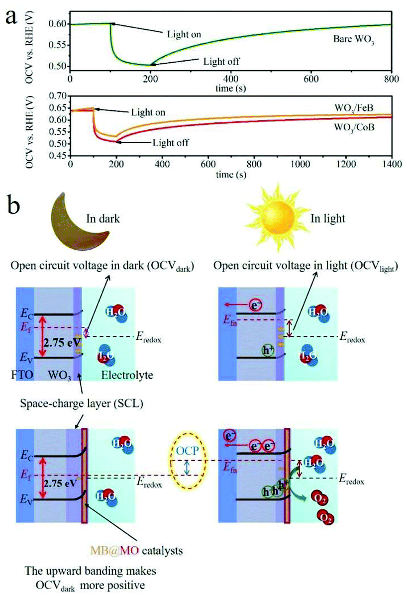 | ||
| Fig. 6 (a) OCV time profile of pristine WO3 and WO3/MB photoanodes recorded in Ar atmosphere. (b) Band structures and band bending schematics of the WO3 based photoanodes. | ||
It has been demonstrated that an enlarged band bending at the SCL of WO3, correlated with changes in surface states, is indicative of the facilitated separation of photoexcited electron–hole pairs and prolonged carrier lifetime.43,44 In the OCV time profile (Fig. 6a), the OCP upraises from pristine WO3 to WO3/MB photoanodes, which thus indicates the enlarged band bending and promoted charge carrier separation.
Fig. 6b schematically summarizes the band structures and band bending diagrams relative to OCVdark and OCVlight values. As for WO3 photoanode, the relative high OCVdark was achieved when it was immersed in solution, because of the Fermi-level pinning by surface trapped electrons (Fig. 6b).4 It implies the upward band bending nature of the electrode in equilibrium with the electrolyte in dark.43 In contrast, a moderate OCVlight under illumination suggests the flattened band induced by photoexcited carrier.43 By the introduction of MB catalysts, the Ef shifts more positively compared to pristine photoanode, due to the mitigated Ef pinning effect by passivating surface trapping states.4 Therefore, a upgraded OCP value is achieved after coupling MB to WO3 photoanodes.4,43
It is noteworthy that in the OCV measurements the catalytic and kinetic impacts can be excluded, because within the system the current originating from the hypothetic redox reactions does not pass steadily.43 Meanwhile, the Ar atmosphere also prevented the measurements being interfered from the surface states passivation by dissolved-O2 absorption.
Additionally, in Fig. 6a, the WO3/MB exhibit much slow decay curves after terminating the illumination, specifically, their OCV have not been completely restored even after 1200 s. It further suggests a much longer charge carrier lifetime within the functionalized photoanodes in comparison with the pristine one.45,46 Therefore, the enhanced band bending correlated with changes in surface states is responsible for the prolonged holes lifetime and amended charge carrier recombination in MB modified photoanodes.
In situ formation of core–shell MB@MO catalysts
Since the surface composition and chemical state are crucial to the catalytic performance, XPS was employed to characterize the chemical states of a complementary bare CoB electrode after CA for 20 min. The B 1s high-resolution XP spectrum (Fig. 7a) shows one distinct peak at 191.7 eV corresponding to the photoemission from boron-oxo species, which dominate on the surface of the catalysts after OER, as described in some previous reports.16,20,47 In turn, the Co 2p high-resolution XP spectrum (Fig. 7b) exhibits spin–orbit splitting with two components – Co 2p3/2 at 780.8 eV and Co 2p1/2 at 796.7 eV. The deconvolution of Co 2p3/2 can be done by two peaks at 780.6 and 782.5 eV, which together with the intense satellite features at 785.6 and 789.6 eV manifest a predominant role of Co2+ in the oxide/hydroxide form.16,43 Because of the very limited detection depth of XPS, the signals from elemental B and Co beneath the surface layer are hard to be detected here.48 On the other hand, the identical forms of Co and B species (confirmed by the Co 2p and B 1s components appearing in the same binding energies) are found for the bare CoB electrode soaked in distilled water for 1 min and dried at 50 °C (Fig. S15†). | ||
| Fig. 7 XPS core level analyses of (a) B 1s, (b) Co 2p. (c) STEM EELS spectrum of CoB electrode. All data were recorded on a CoB electrode that has been subject to CA at 1.23 VRHE under illumination. | ||
A representative STEM EELS spectrum (Fig. 7c) was extracted from the edge of the sample. The data were acquired in spectrum imaging mode, which allows us to separate the edge contributions from the bulk. The EELS spectrum in Fig. 7c has been deconvolved with the low-loss EELS spectrum. The Energy-Loss Near-Edge Structure (ELNES) fingerprint on the resulting spectral shape is very similar to CoO.
In combination with XPS, these results imply the existence of a CoOx-rich layer, being demonstrated as one of the active species.49 The shell is formed in situ on the surface of the catalyst during PEC water oxidation. The active form of the catalyst is thus inferred to consist of a MB core wrapped by a MO-rich layer, and is represented as MB@MO (Fig. 7 and 8). Similar layers on the surface of core–shell like catalysts had also been revealed to be responsible for promoted OER.50,51
Fig. 8a summarizes the structural evolution steps for the WO3/MB@MO photoanodes and the corresponding scheme for accelerated charge carrier migration is shown in Fig. 8b.
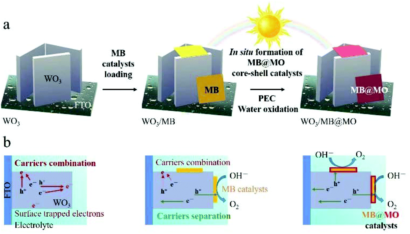 | ||
| Fig. 8 (a) Fabrication of the FTO/WO3/MB@MO photoanodes, including (1) synthesis of WO3 thin film on FTO, (2) surface modification with MB catalysts, (3) in situ formation of FTO/WO3/MB@MO photoanodes during PEC measurement. (b) Photogenerated charge carrier recombination and separation processes in pristine WO3, WO3/MB and WO3/MB@MO photoanodes. | ||
Conclusions
In summary, we have integrated crystalline CoB and FeB nanostructures as catalysts with WO3 photoanodes for PEC water oxidation for the first time. The modification of the WO3 surface enables a ca. 1.6-fold upsurge of the photocurrent and improves its stability. The WO3 photoanodes functionalized with CoB also surpass the PEC performance of WO3/Co-Bi and WO3/Co(OH)x photoanodes. Kinetic analysis demonstrates that the enlarged band bending, correlated with the passivation of surface states which inhibits recombination, is responsible for the augmented charge carrier separation in heterojunction electrodes. The in situ reconstructed catalyst surface MB@MO is the active catalytic center for the water oxidation. The present study highlights the significance of interface interactions within heterojunction systems for future development of photoelectrodes.Conflicts of interest
There are no conflicts to declare.Acknowledgements
C. L. would like to appreciate the China Scholarship Council (CSC) for Ph.D. scholarship. B. P. T. F. acknowledges financial support by the National Science foundation (Career award no. DMR-1654780). A. S. would like to thank Stockholm University for a Start-Up grant. We thank Professor Ulrich Simon for access to electron microscopy facilities. The XPS measurements were carried out with the equipment purchased with the financial support of the European Regional Development Fund in the framework of the Polish Innovation Operational Program (contract no. POIG.02.01.00-12-023/08). K. Y. was partly supported by JSPS KAKENHI grant number JP19K05643.Notes and references
- T. Hisatomi and K. Domen, Nat. Catal., 2019, 2, 387–399 CrossRef CAS.
- G. Glenk and S. Reichelstein, Nat. Energy, 2019, 4, 216–222 CrossRef CAS.
- J. M. V. Nsanzimana, R. Dangol, V. Reddu, S. Duo, Y. Peng, K. N. Dinh, Z. Huang, Q. Yan and X. Wang, ACS Appl. Mater. Interfaces, 2019, 11, 846–855 CrossRef CAS PubMed.
- K.-H. Ye, H. Li, D. Huang, S. Xiao, W. Qiu, M. Li, Y. Hu, W. Mai, H. Ji and S. Yang, Nat. Commun., 2019, 10, 3687 CrossRef PubMed.
- T. Higashi, H. Nishiyama, Y. Suzuki, Y. Sasaki, T. Hisatomi, M. Katayama, T. Minegishi, K. Seki, T. Yamada and K. Domen, Angew. Chem., Int. Ed., 2019, 58, 2300–2304 CrossRef CAS PubMed.
- S. Vanka, E. Arca, S. Cheng, K. Sun, G. A. Botton, G. Teeter and Z. Mi, Nano Lett., 2018, 18, 6530–6537 CrossRef CAS PubMed.
- K. Choi, K. Kim, I. K. Moon, J. Bang and J. Oh, Nanoscale, 2019, 11, 15367–15373 RSC.
- M. Davi, A. Drichel, M. Mann, T. Scholz, F. Schrader, A. Rokicinska, P. Kustrowski, R. Dronskowski and A. Slabon, J. Phys. Chem. C, 2017, 121, 26265–26274 CrossRef.
- Z. Ma, T. Thersleff, A. L. Görne, N. Cordes, Y. Liu, S. Jakobi, A. Rokicinska, Z. G. Schichtl, R. H. Coridan, P. Kustrowski, W. Schnick, R. Dronskowski and A. Slabon, ACS Appl. Mater. Interfaces, 2019, 11, 19077–19086 CrossRef CAS PubMed.
- R. Nebel, K. M. Macounová, H. Tarábková, L. Kavan and P. Krtil, J. Phys. Chem. C, 2019, 123, 10857–10867 CrossRef CAS.
- D. K. Lee, D. Lee, M. A. Lumley and K.-S. Choi, Chem. Soc. Rev., 2019, 48, 2126–2157 RSC.
- Z. Ma, O. Linnenberg, A. Rokicinska, P. Kustrowski and A. Slabon, J. Phys. Chem. C, 2018, 122, 19281–19288 CrossRef CAS.
- M. Davi, G. Ogutu, F. Schrader, A. Rokicinska, P. Kustrowski and A. Slabon, Eur. J. Inorg. Chem., 2017, 2017, 4267–4274 CrossRef CAS.
- C. Ding, J. Shi, Z. Wang and C. Li, ACS Catal., 2017, 7, 675–688 CrossRef CAS.
- J. A. Seabold and K.-S. Choi, J. Am. Chem. Soc., 2012, 134, 2186–2192 CrossRef CAS PubMed.
- J. Masa, P. Weide, D. Peeters, I. Sinev, W. Xia, Z. Sun, C. Somsen, M. Muhler and W. Schuhmann, Adv. Energy Mater., 2016, 6, 1502313 CrossRef.
- J. M. V. Nsanzimana, V. Reddu, Y. Peng, Z. Huang, C. Wang and X. Wang, Chem. – Eur. J., 2018, 24, 18502–18511 CrossRef CAS PubMed.
- J. Masa, I. Sinev, H. Mistry, E. Ventosa, M. de la Mata, J. Arbiol, M. Muhler, B. Roldan Cuenya and W. Schuhmann, Adv. Energy Mater., 2017, 7, 1700381 CrossRef.
- W. Jiang, S. Niu, T. Tang, Q.-H. Zhang, X. Liu, Y. Zhang, Y.-Y. Chen, J.-H. Li, L. Gu, L.-J. Wan and J.-S. Hu, Angew. Chem., Int. Ed., 2017, 56, 6572–6577 CrossRef CAS PubMed.
- K. Dang, X. Chang, T. Wang and J. Gong, Nanoscale, 2017, 9, 16133–16137 RSC.
- A. Liao, H. He, Z. Fan, G. Xu, L. Li, J. Chen, Q. Han, X. Chen, Y. Zhou and Z. Zou, J. Catal., 2017, 352, 113–119 CrossRef CAS.
- H. Han, Y. Hong, J. Woo, S. Mhin, K. M. Kim, J. Kwon, H. Choi, Y. Chung and T. Song, Adv. Energy Mater., 2019, 9, 1803799 CrossRef.
- P. R. Jothi, K. Yubuta and B. P. T. Fokwa, Adv. Mater., 2018, 30, 1704181 CrossRef PubMed.
- H. Park, Y. Zhang, J. P. Scheifers, P. R. Jothi, A. Encinas and B. P. T. Fokwa, J. Am. Chem. Soc., 2017, 139, 12915–12918 CrossRef CAS PubMed.
- D. Hu, P. Diao, D. Xu and Q. Wu, Nano Res., 2016, 9, 1735–1751 CrossRef CAS.
- P. Chen, K. Xu, T. Zhou, Y. Tong, J. Wu, H. Cheng, X. Lu, H. Ding, C. Wu and Y. Xie, Angew. Chem., Int. Ed., 2016, 55, 2488–2492 CrossRef CAS PubMed.
- C. Zhen, L. Wang, G. Liu, G. Q. (Max) Lu and H. Cheng, Chem. Commun., 2013, 49, 3019–3021 RSC.
- M. Yang, H. He, H. Zhang, X. Zhong, F. Dong, G. Ke, Y. Chen, J. Du and Y. Zhou, Electrochim. Acta, 2018, 283, 871–881 CrossRef CAS.
- W. Kim, T. Tachikawa, D. Monllor-Satoca, H. Kim, T. Majima and W. Choi, Energy Environ. Sci., 2013, 6, 3732–3739 RSC.
- J. Huang, Y. Zhang and Y. Ding, ACS Catal., 2017, 7, 1841–1845 CrossRef CAS.
- X. Ren, R. Ge, Y. Zhang, D. Liu, D. Wu, X. Sun, B. Du and Q. Wei, J. Mater. Chem. A, 2017, 5, 7291–7294 RSC.
- C. Xie, Y. Wang, D. Yan, L. Tao and S. Wang, Nanoscale, 2017, 9, 16059–16065 RSC.
- L. Wang, B. Zhang and Q. Rui, ACS Catal., 2018, 8, 10564–10572 CrossRef CAS.
- G. Zhang, S. Zang and X. Wang, ACS Catal., 2015, 5, 941–947 CrossRef CAS.
- B. Dong, J. Cui, Y. Gao, Y. Qi, F. Zhang and C. Li, Adv. Mater., 2019, 31, 1808185 CrossRef PubMed.
- M. Ertl, Z. Ma, T. Thersleff, P. Lyu, S. Huettner, P. Nachtigall, J. Breu and A. Slabon, Inorg. Chem., 2019, 58, 9655–9662 CrossRef CAS PubMed.
- M. Ma, K. Zhang, P. Li, M. S. Jung, M. J. Jeong and J. H. Park, Angew. Chem., Int. Ed., 2016, 55, 11819–11823 CrossRef CAS PubMed.
- Y. Zhong, Z. Li, X. Zhao, T. Fang, H. Huang, Q. Qian, X. Chang, P. Wang, S. Yan, Z. Yu and Z. Zou, Adv. Funct. Mater., 2016, 26, 7156–7163 CrossRef CAS.
- S. Wang, H. Chen, G. Gao, T. Butburee, M. Lyu, S. Thaweesak, J.-H. Yun, A. Du, G. Liu and L. Wang, Nano Energy, 2016, 24, 94–102 CrossRef CAS.
- L. Ma, H. Fan, M. Li, H. Tian, J. Fang and G. Dong, J. Mater. Chem. A, 2015, 3, 22404–22412 RSC.
- L. Ma, H. Fan, J. Wang, Y. Zhao, H. Tian and G. Dong, Appl. Catal., B, 2016, 190, 93–102 CrossRef CAS.
- D. Kim, Z. Zhang and K. Yong, Nanoscale, 2018, 10, 20256–20265 RSC.
- M. Zhong, T. Hisatomi, Y. Kuang, J. Zhao, M. Liu, A. Iwase, Q. Jia, H. Nishiyama, T. Minegishi, M. Nakabayashi, N. Shibata, R. Niishiro, C. Katayama, H. Shibano, M. Katayama, A. Kudo, T. Yamada and K. Domen, J. Am. Chem. Soc., 2015, 137, 5053–5060 CrossRef CAS PubMed.
- S. Corby, E. Pastor, Y. Dong, X. Zheng, L. Francàs, M. Sachs, S. Selim, A. Kafizas, A. A. Bakulin and J. R. Durrant, J. Phys. Chem. Lett., 2019, 10, 5395–5401 CrossRef CAS PubMed.
- Y. Wang, S. Jin, G. Pan, Z. Li, L. Chen, G. Liu and X. Xu, J. Mater. Chem. A, 2019, 7, 5702–5711 RSC.
- Y. Wang, S. Jin, X. Sun, S. Wei, L. Chen and X. Xu, Appl. Catal., B, 2019, 245, 10–19 CrossRef CAS.
- T. Tan, P. Han, H. Cong, G. Cheng and W. Luo, ACS Sustainable Chem. Eng., 2019, 7, 5620–5625 CrossRef CAS.
- L.-K. Wu, W. Wu, J. Xia, H. Cao, G. Hou, Y. Tang and G. Zheng, Electrochim. Acta, 2017, 254, 337–347 CrossRef CAS.
- D. Li, J. Shi and C. Li, Small, 2018, 14, 1704179 CrossRef PubMed.
- L.-A. Stern, L. Feng, F. Song and X. Hu, Energy Environ. Sci., 2015, 8, 2347–2351 RSC.
- N. T. Suen, S. F. Hung, Q. Quan, N. Zhang, Y. J. Xu and H. M. Chen, Chem. Soc. Rev., 2017, 46, 337–365 RSC.
Footnote |
| † Electronic supplementary information (ESI) available: Experimental section, supplemental figures, table and corresponding illustration. See DOI: 10.1039/c9nr09818f |
| This journal is © The Royal Society of Chemistry 2020 |