Bimetal–organic framework MIL-53(Co–Fe): an efficient and robust electrocatalyst for the oxygen evolution reaction†
Maowen
Xie
a,
Yan
Ma
a,
Dunmin
Lin
 a,
Chenggang
Xu
a,
Fengyu
Xie
a,
Chenggang
Xu
a,
Fengyu
Xie
 *a and
Wen
Zeng
 *b
*b
aCollege of Chemistry and Materials Science, Sichuan Normal University, Chengdu 610068, Sichuan, China. E-mail: xiefengyu161@163.com
bCollege of Materials Science and Engineering, Chongqing University, Chongqing, China
First published on 22nd November 2019
Abstract
Rationally designing high-efficiency catalysts for the oxygen evolution reaction (OER) is extremely important for developing sustainable energy technologies, but remains a major research challenge. In this paper, a Co/Fe-imidazole-based bimetal–organic framework nanosheet array grown on a nickel foam [MIL-53(Co–Fe)/NF] was prepared via a facile solvothermal process. Surprisingly, MIL-53(Co–Fe)/NF shows excellent OER activity with overpotential as low as 262 mV at 100 mA cm−2, much lower than those of the single metal-based MOFs, and even comparable to that of the precious RuO2. The results indicate that the synergetic effect of co-doped Fe and Co makes a crucial contribution to the high activity of the bimetal-based MOF catalyst. Additionally, this catalyst also displays outstanding long-term electrochemical durability for at least 80 h.
Industrially profitable water electrolysis is a promising strategy for the mass production of high-purity hydrogen, and the use of hydrogen as a fuel has been regarded as an ideal alternative for alleviating environmental pollution and energy crisis.1,2 Considering that the sluggish kinetics of the oxygen evolution reaction (OER) is the essential half-reaction of water splitting, the development of efficient OER electrocatalysts is vitally desirable, even utilizing noble-metal catalysts (IrO2 and RuO2).3,4 Accordingly, this has prompted researchers to search high-efficiency and cost-effective OER catalysts.5
Recent studies have been made to search for noble-metal-free OER catalysts, including 3d transition metal chalcogenides,6 phosphates,7 perovskite oxides8 and metal organic frameworks (MOFs).9–11 Among these nonprecious metal-based electrocatalysts, MOFs have attracted tremendous research efforts by reason of large specific surface area, more active sites and large porosity, making MOFs suitable catalyst candidates.12–15 Unfortunately, their electrocatalytic performances are far from meeting the needs of practical applications due to their instability,16 insulativity,17 and solvent-free18 or water-solvent conditions.19 To circumvent these drawbacks, extensive researches endeavors have been devoted to explore multiple approaches, such as using high-valence metal ions and metal-ion metathesis.20 For instance, Fe-based MOFs21 as electrocatalysts for OER have been investigated recently, and they were found to be stable and active for OER. Meanwhile, Cu-MOFs15 and Co-MOFs22 were reported as high-efficiency OER catalysts. Compared with single metal-based MOFs, theoretical computations demonstrate that bimetal-based MOFs exhibit superior catalytic performance owing to the synergetic effect between the two types of metal species.23,24 It is expected that designing bimetallic-based MOFs is certainly a plausible strategy to develop high-performance catalysts, but the number of the related reports are still limited.
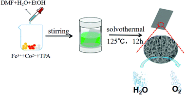
Herein, we report an evident improvement in the OER activity by incorporating Fe and Co into a MOF nanosheet array supported on a nickel foam (MIL-53(Co–Fe)/NF), and the fabrication process is shown in Scheme 1. Compared with the single metal-based MOFs, MIL-53(Co–Fe)/NF exhibits improved OER activity with ultralow overpotential of 262 mV to afford 100 mA cm−2 current density, revealing that co-doped Fe and Co into MOFs could further boost the intrinsic OER activity of MOFs. Particularly, it also shows outstanding and long-term catalytic durability.
After the solvothermal process, the 2θ values of peaks in the XRD pattern of MIL-53 (Co–Fe)/NF (Fig. 1a) are consistent with the single crystal data simulation of [Co2(OH)2C8H4O4] in the reported literature.25 The diffraction peak at 8.9° is indexed to the (200) plane of the MIL-53 structure. In addition, there are two prominent and sharp diffraction peaks at 44.5° and 51.8°, corresponding to the (111) and (200) crystal faces of Ni (JCPDS: 04-0850), which are derived from the Ni foam. Furthermore, we tested the XRD diffraction peaks of MIL-53 (Co)/NF and MIL-53 (Fe)/NF (Fig. S1 and S2,† respectively). The Fourier transform infrared (FT-IR) spectrum (Fig. 1b) displays the functional groups of MIL-53(Co–Fe)/NF in the range of 4000–500 cm−1; two powerful absorption bands at 1377 and 1585 cm−1 are associated with the characteristic antisymmetric and symmetric O–C![[double bond, length as m-dash]](https://www.rsc.org/images/entities/char_e001.gif) O stretching frequency vibrations, respectively. Another two peaks at 748 and 3422 cm−1 are also observed due to the C–H bonding vibration and the O–H stretching mode of the benzene ring, respectively. Further, the metal–oxygen bond vibration (ν(Fe–O)) at 543 cm−1 was observed to be attributed to the interactions between the carboxyl group of terephthalic acid and Fe atom.26 The Raman spectrum (Fig. S3†) of the MIL-53(Co–Fe)/NF shows a new doublet with peaks at 1605 and 1420 cm−1, which are in accordance with the stretching modes of the carboxylate group. Moreover, three peaks at 860, 810 and 629 cm−1 are caused by the formation of a C–H bond produced from the benzene ring in the sample.27 The scanning electron microscopy (SEM) image of MIL-53(Co–Fe)/NF (Fig. 1c) indicates the full coverage of the MIL-53(Co–Fe) nanosheet array on the Ni foam. A high-resolution TEM (HRTEM) image was obtained to get insight into the structure of the MIL-53(Co–Fe)/NF catalyst. As shown in Fig. 1d, the as-prepared catalyst presented ultrathin and almost transparent sheet-like morphology. The energy-dispersive X-ray spectroscopy (EDX) analysis suggests the presence of multi-components including C, O, Co and Fe elements in MIL-53(Co–Fe)/NF (Fig. S4†). As shown in Fig. S5,† the corresponding EDX elemental mapping images indicate the uniform distribution of Co, Fe, C and O elements in the resulting MIL-53(Co–Fe) product.
O stretching frequency vibrations, respectively. Another two peaks at 748 and 3422 cm−1 are also observed due to the C–H bonding vibration and the O–H stretching mode of the benzene ring, respectively. Further, the metal–oxygen bond vibration (ν(Fe–O)) at 543 cm−1 was observed to be attributed to the interactions between the carboxyl group of terephthalic acid and Fe atom.26 The Raman spectrum (Fig. S3†) of the MIL-53(Co–Fe)/NF shows a new doublet with peaks at 1605 and 1420 cm−1, which are in accordance with the stretching modes of the carboxylate group. Moreover, three peaks at 860, 810 and 629 cm−1 are caused by the formation of a C–H bond produced from the benzene ring in the sample.27 The scanning electron microscopy (SEM) image of MIL-53(Co–Fe)/NF (Fig. 1c) indicates the full coverage of the MIL-53(Co–Fe) nanosheet array on the Ni foam. A high-resolution TEM (HRTEM) image was obtained to get insight into the structure of the MIL-53(Co–Fe)/NF catalyst. As shown in Fig. 1d, the as-prepared catalyst presented ultrathin and almost transparent sheet-like morphology. The energy-dispersive X-ray spectroscopy (EDX) analysis suggests the presence of multi-components including C, O, Co and Fe elements in MIL-53(Co–Fe)/NF (Fig. S4†). As shown in Fig. S5,† the corresponding EDX elemental mapping images indicate the uniform distribution of Co, Fe, C and O elements in the resulting MIL-53(Co–Fe) product.
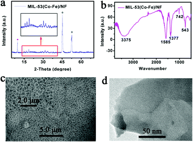 | ||
| Fig. 1 Characterizations of the structure and morphology of MIL-53 (Co–Fe)/NF (a) X-ray diffraction (XRD) pattern, (b) FT-IR spectrum, (c) SEM images and (d) HRTEM image. | ||
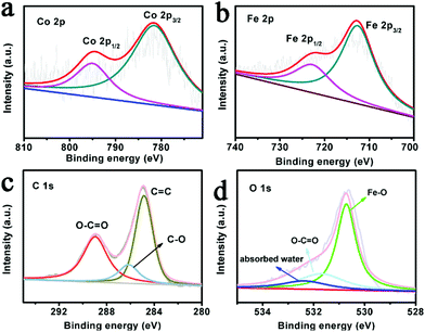
X-ray photoelectron spectroscopy (XPS) analysis further confirmed the presence of the Co, Fe, C and O elements. In Fig. 2a, the high resolution spectra of Co 2p for MIL-53(Co–Fe)/NF shows the binding energies of Co 2p3/2 and Co 2p1/2 at 780.8 eV and 796.7 eV, respectively, implying the existence of a high-spin Co2+ state.28 As shown in Fig. 2b, the binding energy values of Fe 2p are 712.5 and 725.0 eV, corresponding to Fe 2p3/2 and Fe 2p1/2, implying the presence of Fe in the Fe3+ oxidation state. The XPS spectrum of C 1s shown in Fig. 2c confirms three types of carbon, namely, carbon components (C–H) in aromatic rings at 284.8 eV, carboxylate groups (O–C![[double bond, length as m-dash]](https://www.rsc.org/images/entities/char_e001.gif) O) from intercalated benzoate anions at 288.8 eV and C–O at 286.0 eV. Fig. 2d shows three peaks in the O 1s region at approximately 530.8, 532.0 and 533.0 eV, implying the existence of Fe–O bonds and the coordination between the group of TPA linkers and absorbed water, respectively.29,30 All these observations suggest that MIL-53(Co–Fe)/NF was successfully prepared.
O) from intercalated benzoate anions at 288.8 eV and C–O at 286.0 eV. Fig. 2d shows three peaks in the O 1s region at approximately 530.8, 532.0 and 533.0 eV, implying the existence of Fe–O bonds and the coordination between the group of TPA linkers and absorbed water, respectively.29,30 All these observations suggest that MIL-53(Co–Fe)/NF was successfully prepared.
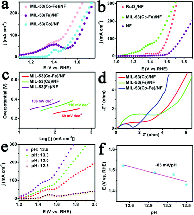
The electrocatalytic OER performance of MIL-53(Co–Fe)/NF was examined in 1.0 M KOH. For comparison, bare NF, RuO2/NF, MIL-53(Co)/NF and MIL-53(Fe)/NF were also tested. For the polarization curves, the ohmic potential drop (iR) correction was applied to all initial data, unless specifically stated.31 As indicated by an oxidation peak of surface metal species (M–OH to M–OOH) between 1.20 and 1.50 V, all MOFs show catalytic activities toward OER (Fig. 3a and b). As expected, bare NF displayed poor electrochemical performance, while the single metal-based MOFs were highly effective, requiring 348 mV and 380 mV overpotential to afford 100 mA cm−2. To achieve the same catalytic current density, the bimetal-based MOF demands a much lower overpotential of 262 mV, in sharp contrast to the single metal-based MOFs. To get the optimum catalytic activities, the LSV curves of MIL-53(Co–Fe)/NF with different mole ratios of Co/Fe and under different solvothermal temperatures (from 105 °C to 145 °C) were recorded and shown in Fig. S6 and S7,† respectively. These results suggest that mole ratios of Co/Fe and solvothermal temperature have a significant influence on the OER activity of MIL-53(Co–Fe)/NF. Accordingly, the optimized mole ratio of Co/Fe is (0.5![[thin space (1/6-em)]](https://www.rsc.org/images/entities/char_2009.gif) :
:![[thin space (1/6-em)]](https://www.rsc.org/images/entities/char_2009.gif) 0.5) and the optimized solvothermal temperature is 125 °C. It is worth mentioning that MIL-53(Co–Fe)/NF has a comparable overpotential to RuO2 at 100 mA cm−2. Remarkably, MIL-53(Co–Fe)/NF also outperformed other reported non-noble metal-based OER catalysts (see Table S1†). Thus, the positive effect of co-doped Fe and Co into MOFs for OER is confirmed. The reason may be that iron cations are active sites and cobalt cations assist the formation of OER active sites in the MOFs. Furthermore, experimental data indicate that the synergetic effect between the two types of metal species can improve the activity of the OER catalysts. Kinetics of the as-prepared MIL-53(Co–Fe)/NF was evaluated utilizing the Tafel plots.32 The bimetallic electrocatalyst demonstrates more effective kinetics than the single metal electrocatalysts, as shown in Fig. 3c, due to different morphology and resistance to charge transfer of and within the catalysts, respectively. Fig. 3d shows the Nyquist plots of MIL-53(Co–Fe)/NF, MIL-53(Co)/NF and MIL-53(Fe)/NF. Clearly, the semi-circle radius of the bimetallic-based material is significantly reduced, indicating excellent charge-transfer capability and excellent OER intrinsic activity relative to the single-metal materials. Thus, the synergetic effect of co-doped Fe and Co was confirmed again. However, the questions remain on what is the electrocatalytic behaviour and water oxidation mechanism of MIL-53(Co–Fe)/NF. The pH versus potential dependence of the oxidation peak in anodic prefecture of the catalyst was investigated (Fig. 3e). The obtained slope value is about −83 mV per pH (Fig. 3f), which is very close to the theoretical value of −96 mV per pH, corresponding to the loss of 1e− accompanied by the transfer of ∼1.5 protons.33
0.5) and the optimized solvothermal temperature is 125 °C. It is worth mentioning that MIL-53(Co–Fe)/NF has a comparable overpotential to RuO2 at 100 mA cm−2. Remarkably, MIL-53(Co–Fe)/NF also outperformed other reported non-noble metal-based OER catalysts (see Table S1†). Thus, the positive effect of co-doped Fe and Co into MOFs for OER is confirmed. The reason may be that iron cations are active sites and cobalt cations assist the formation of OER active sites in the MOFs. Furthermore, experimental data indicate that the synergetic effect between the two types of metal species can improve the activity of the OER catalysts. Kinetics of the as-prepared MIL-53(Co–Fe)/NF was evaluated utilizing the Tafel plots.32 The bimetallic electrocatalyst demonstrates more effective kinetics than the single metal electrocatalysts, as shown in Fig. 3c, due to different morphology and resistance to charge transfer of and within the catalysts, respectively. Fig. 3d shows the Nyquist plots of MIL-53(Co–Fe)/NF, MIL-53(Co)/NF and MIL-53(Fe)/NF. Clearly, the semi-circle radius of the bimetallic-based material is significantly reduced, indicating excellent charge-transfer capability and excellent OER intrinsic activity relative to the single-metal materials. Thus, the synergetic effect of co-doped Fe and Co was confirmed again. However, the questions remain on what is the electrocatalytic behaviour and water oxidation mechanism of MIL-53(Co–Fe)/NF. The pH versus potential dependence of the oxidation peak in anodic prefecture of the catalyst was investigated (Fig. 3e). The obtained slope value is about −83 mV per pH (Fig. 3f), which is very close to the theoretical value of −96 mV per pH, corresponding to the loss of 1e− accompanied by the transfer of ∼1.5 protons.33
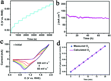
The multi-step chronopotentiometric curve for MIL-53(Co–Fe)/NF (Fig. 4a) showed that the potential leveled out at 0.53 V vs. RHE for a current density of 4 mA cm−2 and remained unchanged in the rest of the 500 s. The results suggest that MIL-53(Co–Fe)/NF can deliver the rapid outward release of oxygen and inward diffusion of the electrolyte, indicating an excellent mass transportation behaviour.34 Stability also plays a key role in the practical application of the catalyst, so we studied the stability of MIL-53(Co–Fe)/NF by continuous cyclic voltammetry. As observed, the LSV curve after 500 cycles barely changes compared to the initial curve (Fig. S8†). Moreover, we further explored the durability of MIL-53(Co–Fe)/NF. As shown in Fig. 4b, MIL-53(Co–Fe)/NF displays remarkable durability at fixed a current density of 100 mA cm−2 over 80 h of electrolytic water oxidation, resulting in the enhancement of the intrinsic OER activity of MOFs. After the stability test, we collected HRTEM images (Fig. S9†) and XPS spectra (Fig. S10†) of MIL-53 (Co–Fe)/NF. The morphology and chemical state was unchanged, indicating the exceptional stability of MIL-53(Co–Fe)/NF for OER.
To correlate the electrochemical active surface areas (ECSAs) of the catalyst with the electrocatalytic activity, the double layer capacitance (Cdl) was measured by means of CV curves.35,36 As shown in Fig. S11,† the higher Cdl of MIL-53(Co–Fe)/NF (99 mF cm−2) compared with that of MIL-53(Co)/NF (60 mF cm−2) and MIL-53(Fe)/NF (19.5 mF cm−2), suggests the much higher surface roughness and more catalytically active sites of MIL-53(Co–Fe)/NF. Turnover Frequency (TOF) is another important parameter used to evaluate the inherent catalytic performance of the electrode. A series of cyclic voltammograms for MIL-53(Co–Fe)/NF (Fig. 4c) indicated that oxidation peak currents were linearly dependent on scan rates (Fig. S12a†). As a result, MIL-53(Co–Fe)/NF achieved a highest TOF of 0.47 mol O2 per s at an overpotential of 300 mV (Fig. S12b†). We also investigated the TOF value for MIL-53(Co–Fe)/NF after 20 h. As shown in Fig. S13,† the TOF demonstrates an insignificant variation, revealing that the catalyst retained catalytic activity. Finally, we determined the faradaic efficiency (FE) by comparing the quantity of practically evolved oxygen with theoretically calculated oxygen (assuming 100% FE) and with the FE values obtained via published literature methods. As observed in Fig. 4d, there is an approximate agreement of the measured value and theoretical value of nearly 100% FE for evolution oxygen on the MIL-53 (Co–Fe) electrode.37
In summary, we proposed a facile method to improve the OER activity of MOF nanosheets by incorporating Fe and Co into MOFs on an Ni foam. Interestingly, the as-synthesized MIL-53 (Co–Fe) nanosheet array drives 100 mA cm−2 with only 262 mV overpotential, demonstrating the more effective OER activity of the bimetallic electrocatalyst compared with single metal catalysts. In addition, this catalyst also exhibits outstanding long-term electrochemical durability for 80 h and high TOF of 0.47 mol O2 per s at 300 mV overpotential. This study provides more insight into MOFs as highly active OER electrode materials and opens up new strategies for developing promising high-efficiency electrocatalysts in practical applications.
Conflicts of interest
The authors declare that they have no conflict of interest.Acknowledgements
This research study was supported by open funds of the state key laboratory of electroanalytical chemistry (SKLEAC201910).References
- L. Xie, R. Zhang, L. Cui, D. Liu, S. Hao, Y. Ma, G. Du, A. M. Asiri and X. Sun, Angew. Chem., Int. Ed., 2017, 56, 1064–1068 CrossRef CAS PubMed.
- K. S. Joya and H. J. M. de Groot, ACS Catal., 2016, 6, 1768–1771 CrossRef CAS.
- R. Wu, D. P. Wang, K. Zhou, N. Srikanth, J. Wei and Z. Chen, J. Mater. Chem. A, 2016, 4, 13742–13745 RSC.
- J. A. Vigil, T. N. Lambert and B. T. Christensen, J. Mater. Chem. A, 2016, 4, 7549–7554 RSC.
- Y. Gorlin and T. F. Jaramillo, J. Am. Chem. Soc., 2010, 132, 13612–13614 CrossRef CAS PubMed.
- H. Wang, S. Zhuo, Y. Liang, X. Han and B. Zhang, Angew. Chem., Int. Ed., 2016, 55, 9055–9059 CrossRef CAS PubMed.
- P. Jiang, Q. Liu, Y. Liang, J. Tian, A. M. Asiri and X. Sun, Angew. Chem., Int. Ed., 2014, 53, 12855–12859 CrossRef CAS PubMed.
- J. Suntivich, K. J. May, H. A. Gasteiger, J. B. Goodenough and Y. Shao-Horn, Science, 2011, 334, 1383–1385 CrossRef CAS PubMed.
- F. Yang, P. Zhao, X. Hua, W. Luo, G. Cheng, W. Xing and S. Chen, J. Mater. Chem. A, 2016, 4, 16057–16063 RSC.
- J. Huang, Y. Li, R. K. Huang, C. T. He, L. Gong, Q. Hu, L. Wang, Y. T. Xu, X. Y. Tian, S. Y. Liu, Z. M. Ye, F. Wang, D. D. Zhou, W. X. Zhang and J. P. Zhang, Angew. Chem., Int. Ed., 2018, 57, 4632–4636 CrossRef CAS PubMed.
- X. Wang, J. Zhou, H. Fu, W. Li, X. Fan, G. Xin, J. Zheng and X. Li, J. Mater. Chem. A, 2014, 2, 14064–14070 RSC.
- Q. Liang, H. Jin, Z. Wang, Y. Xiong, S. Yuan, X. Zeng, D. He and S. Mu, Nano Energy, 2019, 57, 746–752 CrossRef CAS.
- Y. Guo, P. Yuan, J. Zhang, H. Xia, F. Cheng, M. Zhou, J. Li, Y. Qiao, S. Mu and Q. Xu, Adv. Funct. Mater., 2018, 28, 1805641 CrossRef.
- I. S. Amiinu, Z. Pu, X. Liu, K. A. Owusu, H. G. R. Monestel, F. O. Boakye, H. Zhang and S. Mu, Adv. Funct. Mater., 2017, 27, 1702300 CrossRef.
- R. Wang, X. Y. Dong, J. Du, J. Y. Zhao and S. Q. Zang, Adv. Mater., 2018, 30, 1703711 CrossRef PubMed.
- T. Y. Ma, S. Dai, M. Jaroniec and S. Z. Qiao, J. Am. Chem. Soc., 2014, 136, 13925–13931 CrossRef CAS PubMed.
- F. Sun, L. Li, G. Wang and Y. Lin, J. Mater. Chem. A, 2017, 5, 6849–6859 RSC.
- C. Andronescu, S. Barwe, E. Ventosa, J. Masa, E. Vasile, B. Konkena, S. Moller and W. Schuhmann, Angew. Chem., Int. Ed., 2017, 56, 11258–11262 CrossRef CAS PubMed.
- S.-H. Bae, J.-E. Kim, H. Randriamahazaka, S.-Y. Moon, J.-Y. Park and I.-K. Oh, Adv. Energy Mater., 2017, 7, 1601492 CrossRef.
- T. Liu, A. M. Asiri and X. Sun, Nanoscale, 2016, 8, 3911–3915 RSC.
- P. Du and R. Eisenberg, Energy Environ. Sci., 2012, 5, 6012 RSC.
- X. P. Zhang, C. D. Si, H. Du, R.-M. Kong and F. L. Qu, Inorg. Chem. Front., 2018, 5, 344–347 RSC.
- Y. Liu, H. Cheng, M. Lyu, S. Fan, Q. Liu, W. Zhang, Y. Zhi, C. Wang, C. Xiao, S. Wei, B. Ye and Y. Xie, J. Am. Chem. Soc., 2014, 136, 15670–15675 CrossRef CAS PubMed.
- Z. Fang, B. Bueken, D. E. De Vos and R. A. Fischer, Angew. Chem., Int. Ed., 2015, 54, 7234–7254 CrossRef CAS PubMed.
- J. Yang, Z. Ma, W. Gao and M. Wei, Chemistry, 2017, 23, 631–636 CrossRef CAS PubMed.
- F. Sun, G. Wang, Y. Ding, C. Wang, B. Yuan and Y. Lin, Adv. Energy Mater., 2018, 8, 1800584 CrossRef.
- S. Bordiga, C. Lamberti, G. Ricchiardi, L. Regli, F. Bonino, A. Damin, K. P. Lillerud, M. Bjorgen and A. Zecchina, Chem. Commun., 2004, 2300–2301, 10.1039/B407246D.
- R. Yang, Y. Zhou, Y. Xing, D. Li, D. Jiang, M. Chen, W. Shi and S. Yuan, Appl. Catal., B, 2019, 253, 131–139 CrossRef CAS.
- R. Liang, F. Jing, L. Shen, N. Qin and L. Wu, J. Hazard. Mater., 2015, 287, 364–372 CrossRef CAS.
- V. Chandra, J. Park, Y. Chun, J. W. Lee, I.-C. Hwang and K. S. Kim, ACS Nano, 2010, 4, 3979–3986 CrossRef CAS.
- Y. Gou, L. Yang, Z. Liu, A. M. Asiri, J. Hu and X. Sun, Inorg. Chem., 2018, 57, 1220–1225 CrossRef CAS.
- M. Xie, X. Xiong, L. Yang, X. Shi, A. M. Asiri and X. Sun, Chem. Commun., 2018, 54, 2300–2303 RSC.
- K. S. Joya, Y. F. Joya and H. J. M. de Groot, Adv. Energy Mater., 2014, 4, 1301929 CrossRef.
- M. Xie, L. Yang, Y. Ji, Z. Wang, X. Ren, Z. Liu, A. M. Asiri, X. Xiong and X. Sun, Nanoscale, 2017, 9, 16612–16615 RSC.
- Z. Pu, J. Zhao, I. S. Amiinu, W. Li, M. Wang, D. He and S. Mu, Energy Environ. Sci., 2019, 12, 952–957 RSC.
- Q. Hu, M. Tang, M. He, N. Jiang, C. Xu, D. Lin and Q. Zheng, J. Power Sources, 2020, 446, 227335 CrossRef CAS.
- C. Liang, P. Zou, A. Nairan, Y. Zhang, J. Liu, K. Liu, S. Hu, F. Kang, H. J. Fan and C. Yang, Energy Environ. Sci., 2020 10.1039/c9ee02388g.
Footnote |
| † Electronic supplementary information (ESI) available. See DOI: 10.1039/c9nr06883j |
| This journal is © The Royal Society of Chemistry 2020 |

