
 Open Access Article
 This Open Access Article is licensed under a Creative Commons Attribution-Non Commercial 3.0 Unported Licence
Boronic acids for functionalisation of commercial multi-layer graphitic material as an alternative to diazonium salts†
Rachel L.
McLaren
 a,
Christian J.
Laycock
a,
David J.
Morgan
bc and
Gareth R.
Owen
*a
a,
Christian J.
Laycock
a,
David J.
Morgan
bc and
Gareth R.
Owen
*a
aSchool of Applied Science, University of South Wales, Treforest, CF37 4AT, UK. E-mail: gareth.owen@southwales.ac.uk
bCardiff Catalysis Institute, School of Chemistry, Cardiff University, Cardiff, CF10 3AT, UK
cHarwellXPS, EPSRC National Research Facility for Photoelectron Spectroscopy, RCaH, Didcot, Oxon OX11 0FA, UK
First published on 21st October 2020
Abstract
A novel radical-based functionalisation strategy for the synthesis of functionalised commercially obtained plasma-synthesised multi-layer graphitic material (MLG) is presented herein. 4-(trifluoromethyl)phenyl boronic acid was utilised as a source of 4-(trifluoromethyl)phenyl radicals to covalently graft upon the graphitic surface of MLG. Such a methodology provides a convenient and safer route towards aryl radical generation, serving as a potential alternative to hazardous diazonium salt precusors. The structure and morphology of the functionalised MLG (Arf-MLG) has been characterised using XPS, Raman, TGA, XRD, SEM, TEM and BET techniques. The XPS quantitative data and Raman spectra provide evidence of successful covalent attachment of 4-(trifluoromethyl)phenyl groups to MLG.
Introduction
Graphene describes an allotropic form of carbon consisting of a single layer hexagonal array of sp2 hybridised carbon atoms. The combination of stacked graphene planes makes up the well-known structure of graphite. Whilst graphite has been known for several hundred years, graphene itself was not isolated until 2004.1 Graphene possesses excellent mechanical, electrical, optical, thermal and biocompatible properties. A whole host of potential applications for these materials has been touted by both academia and industry.2,3 Although research on this material is still in its early stages of development, plenty of applications have been proposed which harness and exploit the aforementioned properties.Notwithstanding all of the aforementioned properties of these materials, there are some significant challenges which hinder the practical application of graphene materials on any large or industrial scale.4 Graphene is a challenging material to work with due to its limited dispersibility within most solvents. Additionally, characterisation challenges are very common.5 Pristine graphene is only available in small laboratory scale quantities whilst larger scale industrially derived graphene contains many defects, oxygen functionalisation and are typically obtained as multi-layer graphitic material (MLG).6 Furthermore it is typically obtained with a broad distribution of sizes and morphologies.
Issues such as processability can be addressed via functionalisation. Functionalisation can also alter the properties of the material in a number of ways. For example, addition of new functional groups can enhance solubility and/or generate new composite materials with specifically designed properties.7,8 The incorporation of additional organic or inorganic moieties to the surface of such materials also creates steric repulsion between the sheets and stacks, thus providing an energy barrier against undesired clumping.9 Furthermore, covalent functionalisation can also alter the graphitic structure by introducing a band gap, thereby allowing the material to switch to lower conductance states.10 It is thus imperative to obtain new, safe routes to introduce covalent functionality to new materials.7,8
Over the 16 years since graphene was first isolated, a vast amount of research has been devoted to the development of methods towards covalently functionalised graphene.11–18 Many of these methodologies utilise hazardous conditions, such as diazonium salts. From a synthetic point of view, diazonium salts provide an excellent and straightforward source of radicals from which the only by-product is nitrogen gas.19 This offers a clean methodology for attaching functional groups to the material. Such radicals combine with radicals present on the surface to form new covalent bonds as demonstrated by a number of groups.20–27 Their application, however, does have some undesirable synthetic conditions which makes it challenging for large scale industrial production. Many diazonium salts decompose violently and can be sensitive to friction and shock.28 As a result, access to radicals through alternative precursors is desirable for the purpose of large-scale functionalisation of graphene and graphitic material.
Through an industrial collaboration, we embarked on an investigation to explore alternative starting materials which allow access to aryl radicals required for covalent functionalisation. From an industrial perspective, plasma-synthesised multi-layer graphitic material29,30 is more accessible and as such there is significant value in finding synthetic methodologies for its derivatisation. As such we aimed to explore these more accessible materials for functionalisation as opposed to graphene. Herein, we wish to report a preliminary account of these investigations. We show that 4-(trifluoromethyl)phenyl radicals, accessed via oxidative conditions of 4-(trifluoromethyl)phenyl boronic acid, can be used to covalently functionalise the outer surfaces of plasma-synthesised MLG, thus forming 4-(trifluoromethyl)phenyl functionalised MLG (Arf-MLG). We also explore the impact of carrying out this functionalisation by examining the changes in relation to the original material. The functionalised material was characterised using XPS, Raman, TGA, XRD, SEM, TEM, and BET spectroscopic and analytical methods.
Results and discussion
Synthesis of Arf-MLG
As a means of exploring alternatives to generate aryl radicals in situ for the purposes of covalently functionalising MLG, we looked at aryl boronic acids as potential sources. Aryl boronic acids are well known for their applications in cross coupling reactions, leading to the formation of C–C bonds. It has previously been demonstrated that aryl radicals can be generated from aryl boronic acids under various oxidative conditions, as an alternative strategy for forming C–C bonds. For example, oxidants and combinations of oxidants such as Mn(OAc)3,31 AgNO3/K2S2O8,32,33 Fe(OTf)3/(tBuO)234 and [Ni(acac)2]/K3PO4/(tBuO)235 have all been employed for these purposes.Baran recently reported the application of a mixture of silver nitrate and potassium persulfate for the formation of C–C bonds.32,33 It has been postulated that the persulfate is reduced by the silver to form both [SO4]2− and [SO4]˙−, which in turn react with the aryl boronic acid to generate aryl radicals (Scheme 1).32 The silver(II) is then reduced back to silver(I) as shown. The transformations proceed within a biphasic aqueous/DCM solvent system.
 | ||
| Scheme 1 Reported mechanism for the generation of aryl radicals using the approach by Baran and co-workers.32 | ||
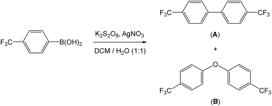
We utilised the Baran protocol for generating aryl radicals in the presence of MLG as a means of functionalising this material. For the purposes of aiding the subsequent characterisation, we chose 4-(trifluoromethyl)phenyl boronic acid as the aryl radical source. This precursor was chosen since it was reported to be most the efficient of those tested (due to the electron withdrawing nature of the CF3 group)32 and it contained fluorine which could be readily observed by X-ray photoelectron spectroscopy (XPS). Prior to the reaction with the graphene material, a control reaction was undertaken. In this control reaction, 4-(trifluoromethyl)phenyl boronic acid was reacted with silver nitrate and potassium persulfate in a 1![[thin space (1/6-em)]](https://www.rsc.org/images/entities/char_2009.gif) :1 mixture of water and DCM (Scheme 2). We found that 44 h stirring at room temperature was sufficient for complete conversion of the starting material. Two products were separated from the DCM layer following work up. These products were identified as the homo-coupled product 4,4′-bis(trifluoromethyl)-1,1′-biphenyl (A) and 4,4′-bis(trifluoromethyl)-1,1′-biphenyl ether (B) by NMR spectroscopy and mass spectrometry, in an approximate 1:1 ratio. The former product (A) was expected, whilst the oxygen-bridged compound (B) was not initially anticipated. We believe that this product originates from the radical species reacting with water to form phenol, which then undergoes a C–O coupling reaction to form the ether product. It was important to confirm the identify of these products since they can also form intermolecular interactions with the surface of the material, which can confuse later interpretation and its characterisation.
:1 mixture of water and DCM (Scheme 2). We found that 44 h stirring at room temperature was sufficient for complete conversion of the starting material. Two products were separated from the DCM layer following work up. These products were identified as the homo-coupled product 4,4′-bis(trifluoromethyl)-1,1′-biphenyl (A) and 4,4′-bis(trifluoromethyl)-1,1′-biphenyl ether (B) by NMR spectroscopy and mass spectrometry, in an approximate 1:1 ratio. The former product (A) was expected, whilst the oxygen-bridged compound (B) was not initially anticipated. We believe that this product originates from the radical species reacting with water to form phenol, which then undergoes a C–O coupling reaction to form the ether product. It was important to confirm the identify of these products since they can also form intermolecular interactions with the surface of the material, which can confuse later interpretation and its characterisation.
 | ||
| Scheme 2 Reaction of 4-(trifluoromethyl)phenyl boronic acid with silver nitrate and potassium persulfate in a biphasic water and DCM reaction. | ||
With evidence of radical generation, we proceeded to repeat the same conditions in the presence of MLG with the aim of functionalising this material with the aryl groups (to form Arf-MLG) with the expectation that both 4,4′-bis(trifluoromethyl)-1,1′-biphenyl and 4,4′-bis(trifluoromethyl)-1,1′-biphenyl ether organic side products would also be present within the reaction mixture (Scheme 3). After 44 h, the newly formed Arf-MLG was isolated from the reaction mixture. This involved purification steps to ensure that organic and inorganic by-products were mostly removed from aryl functionalised MLG (Arf-MLG). The reaction mixture was centrifuged and the resulting powder was subjected to repeated dispersion/centrifugation cycles using large volumes of water, acetonitrile and DCM. The remaining solid material was then placed under high vacuum (10−6 bar) for 168 h.
 | ||
| Scheme 3 Schematic representing the covalent attachment of 4-(trifluoromethyl)phenyl radicals to the MLG to form Arf-MLG. The oxidising conditions leads to further oxidation of the material (see text for details). For clarity, MLG is drawn with only three layers. | ||
Analysis and characterisation of Arf-MLG
The new functionalised material, Arf-MLG, was analysed and characterised via a range of techniques in comparison with the original MLG sample. This allowed us to examine the degree of functionalisation and its impact on the graphitic structure. The results acquired from these techniques are outlined below.X-ray photoelectron spectroscopy
Both original and functionalised samples were examined by XPS, the results of which are presented in Fig. 1–4 and Table 1. Additional details and spectra are provided in the ESI,† in Fig. S1. | ||
| Fig. 1 XPS survey spectra of; (a) MLG and (b) Arf-MLG. | ||
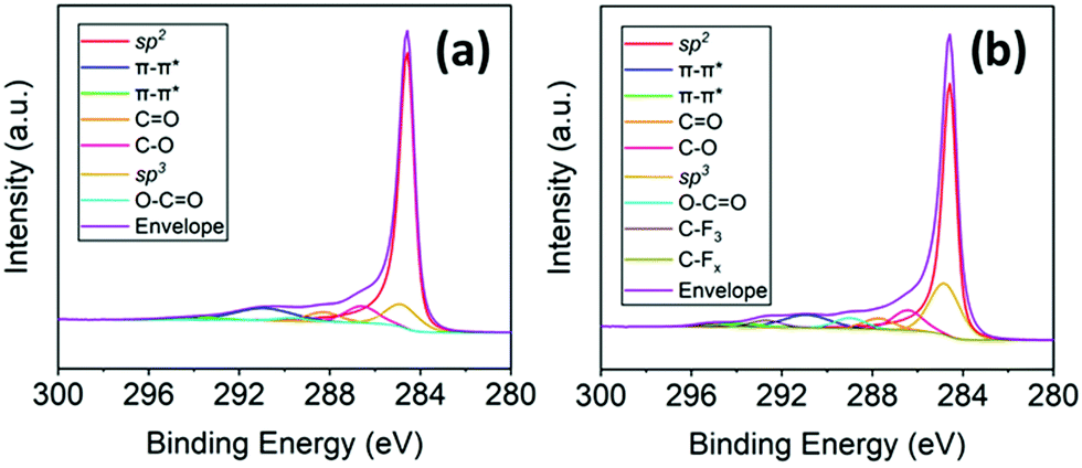 | ||
| Fig. 2 Deconvoluted spectra of C 1s orbital; (a) MLG and (b) Arf-MLG. | ||
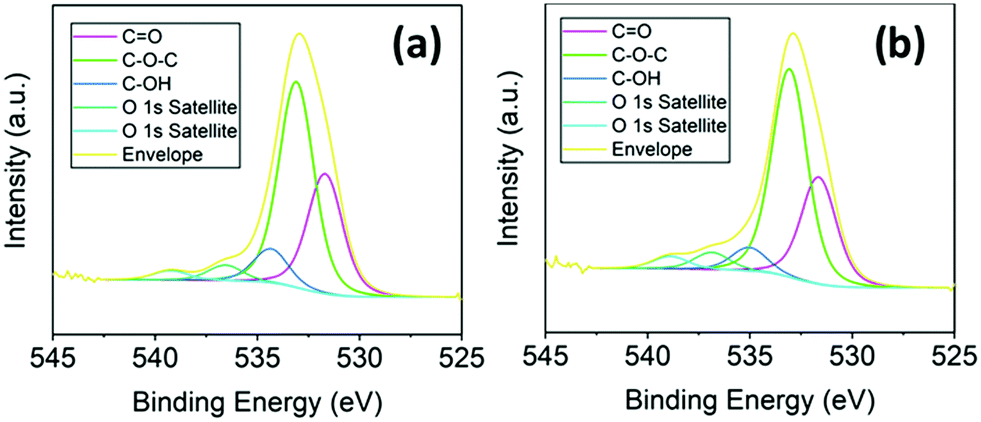 | ||
| Fig. 3 Deconvoluted spectra of O 1s orbital; (a) MLG and (b) Arf-MLG. | ||
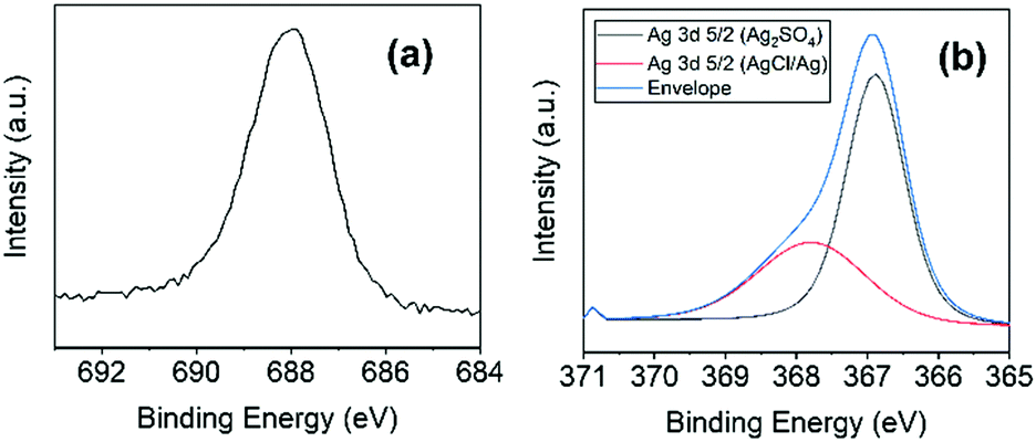 | ||
| Fig. 4 XPS spectra of (a) F 1s and (b) Ag 3d5/2 orbital for Arf-MLG at high resolution (deconvolution of the 3d peak indicates presence of Ag, Ag2SO4 and AgCl). | ||
| Orbital | Atomic concentration (%) | ||
|---|---|---|---|
| MLG | Ar f-MLG | cOx-MLG | |
| C sp2 | 64.3 | 47.5 | 51.2 |
| π–π* | 10.3 | 7.5 | 8.7 |
C![[double bond, length as m-dash]](https://www.rsc.org/images/entities/char_e001.gif) O O |
3.8 | 3.4 | 4.3 |
| C–O | 6.5 | 6.2 | 6.2 |
| C sp3 | 8.8 | 15.8 | 14.9 |
| O–CO |
1.3 | 3.2 | 3.6 |
| C–F3 | — | 2.1 | — |
| C–Fx | — | 0.7 | — |
| Total for carbon | 94.9 | 86.7 | 88.8 |
| N 1s | 0.3 | 0.3 | 0.2 |
| O 1s | 4.8 | 8.5 | 10.7 |
| F 1s | — | 3.5 | — |
| Ag 3d5/2 | — | 0.7 | — |
| S 2p | — | 0.3 | 0.3 |
| Cl 2p | — | 0.4 | — |
We initially characterised MLG and subsequently Arf-MLG to identify and compare surface characteristics, as well as the changes to its elemental composition. The data confirms changes to the elemental composition of the material upon functionalisation (Table 1 and Fig. 1). Most notable is the incorporation of fluorine into Arf-MLG with a relative atomic concentration of 3.5% (at%) for the F 1s orbital.
Deconvolution of the high-resolution XPS spectrum of C 1s spectrum (Fig. 2a) shows that MLG consists of seven environments for the carbon atoms. These were as follows with the binding energies within brackets: C sp2 (284.5 eV), π–π* (290.9 and 294.0 eV), CO (288.3 eV), C–O (286.6 eV), C sp2 (284.8 eV) and O–CO (289.6 eV). A breakdown of the elemental compositions of these components is shown in Table 1. Carbons represent 94.9 at% on the total elemental composition at the surface as expected from graphitic material.
The corresponding C 1s spectra for Arf-MLG (Fig. 2b), consists of nine components corresponding to C sp2 (284.5 eV), π–π* (290.9 and 294.0 eV), CO (287.7 eV), C–O (286.4 eV), C sp2 (284.8 eV), O–CO (289.0 eV), C–Fx (284.9 eV) and CF3 (292.7 eV). Whilst both show graphitic character, Arf-MLG shows additional C–F functionality, originating from the reaction of 4-(trifluoromethyl)phenyl radicals with the graphitic material. Overall, there is a reduction in the percentage carbon in this sample. This is consistent with functionalisation. Furthermore, there is a large increase in the concentration of sp3 hybridised carbon centres, with respect to sp2 hybridised carbons, from 8.8 at% up to 15.8 at%. Some of this increase has be attributed to oxidation of the MLG sample as a result of the oxidising conditions of the reaction (vide infra). As outlined below however, the level of increase in the oxygen content does not account for such a large increase in sp3 hybridised centres. These observations are therefore consistent with some degree of the covalent attachment of the aryl functional groups to the conjugated sp2 network to form Arf-MLG.
The O 1s spectrum for MLG (Fig. 3a) consists of five components CO (531.7 eV), O 1s C–O–C (533.1 eV) and O 1s satellite structures (535.1 eV, 536.9 and 538.9 eV). This confirms the presence of a significant degree of oxygen functionality already within the starting material which originates from its plasma processing. The presence of these oxygen functionalities in MLG corresponds to 4.8 at%. The O 1s spectra for Arf-MLG looks similar to MLG (Fig. 3b), displaying the same components corresponding to CO (531.7 eV), C–O–C (533.1 eV) and O 1s satellite structures (535.1, 536.9 and 538.9 eV), with similar respective ratios. Upon functionalisation however, the oxygen content almost doubled, increasing from 4.8 to 8.5 at%. This increase in oxygen content is attributed to the oxidising reagent which is required for radical generation. In addition to generating the 4-(trifluoromethyl)phenyl radical it also increased the level of oxidation of the graphene surface to some degree. In order to confirm this, we carried out a control reaction under the same conditions with only K2S2O8 and a sample of MLG. We refer to this new material as cOx-MLG. Its surface elemental composition as determined by XPS is also presented in Table 1 for comparison. In this case, a large increase in the oxygen concentration was indeed observed in the sample up to 10.7 at%. Even though the percentage of sp3 carbon centres in Arf-MLG is higher than cOx-MLG, the increase in oxygen content is much lower (cf. 8.5 at% vs. 10.7 at%). This is consistent with the fact that the additional sp3 centres originate from aryl group functionalisation. Furthermore, an increase in oxygen content may also be explained by the fact that a portion of 4-(trifluoromethyl)phenoxide [OC6H4(CF3)] groups could also be covalently bonded to MLG in addition to C6H4(CF3). The ether species (B) was of course found in the control reaction in the absence of MLG (where both A and B were formed).
Fig. 4 highlights the XPS spectra at higher binding energies, indicating the presence of other functional groups. Upon functionalisation, a peak at 687.9 eV (Fig. 4a) confirms the presence of fluorine in the Arf-MLG material. This is not present within the starting material (see Fig. 1a and Table 1). This binding energy is consistent with the presence of the 4-(trifluoromethyl)phenyl functional group.36 Alongside this evidence of incorporation of this functional group are changes to the elemental compositions of carbon and oxygen. The carbon content reduced to 86.5 at%, as expected. Furthermore, the scenario of physisorption of the starting material (trifluoromethylphenyl boronic acid) on to the MLG surface can be ruled out due to the absence of any boron content in the XPS data. The material was washed multiple times and the corresponding filtrates were monitored by 19F and 1H NMR spectroscopy to ensure that the material was free of any unreacted or residual organic species.
The presence of silver (3d orbitals) was observed in the spectrum for Arf-MLG at 367.0 and 372.8 eV. The former Ag 3d5/2 peak was further deconvoluted revealing signals at 367.9 eV and 366.9 eV (Fig. 4b). These resemble silver salts in the form of AgCl/Ag and Ag2SO4, respectively.37,38 This is likely to be due to silver salts retained within the material. These proved rather challenging to remove and they appeared to be trapped within the material despite multiple washings steps. Furthermore, both Arf-MLG and cOx-MLG materials revealed a small percentage of sulfur incorporation as a result of the oxidising agent. Again, these proved challenging to remove completely. Some nitrogen moieties are present within both MLG and Arf-MLG at relatively consistent compositions (see Fig. S4, ESI† and Table 1). The retention of these impurities within Arf-MLG results from the inherent nature of this plasma-synthesied graphitic material where the silver, for example, can get trapped within pores and defects in the material (vide infra).
Determining the decomposition characteristics by TGA
Thermogravimetric analysis (TGA) enables us to examine how the materials decompose, which can be very useful in confirming the nature and degree of functionalisation within the material. Accordingly, the thermal stability of both MLG and Arf-MLG was investigated using TGA measurements at temperatures up to 700 °C. A comparison of the results is depicted in Fig. 5. In both cases, a gradual mass loss is observed with distinct or well-defined mass loss regions. Pristine graphite has been found to show little decomposition until around 600 °C within an O2 atmosphere and up to 1000 °C within a nitrogen atmosphere. Accordingly, mass loss within both samples at these lower temperatures can be attributed to the decomposition of covalently and non-covalently bonded functionality over a gradual period.39,40 Initial mass loss (up to 100 °C), is attributed to the removal of water from the surface. Decomposition from this point is then assigned to the removal of covalently bonded oxygen functionality. In the case of graphene oxide, it has been found that the decomposition of covalently bound oxygen functionality takes place above 150 °C.41Arf-MLG shows a lower thermally stability than MLG, decomposing at a faster rate. This is assigned to the increased covalent functionality it possesses, including more oxygen functionality and 4-(trifluoromethyl)phenyl moieties. The presence of silver salts on the surface of Arf-MLG may also open up other pathways leading to a more rapid mass loss from this material. | ||
| Fig. 5 TGA curves representing the thermal stability of MLG and Arf-MLG. | ||
Examining the graphitic structure by Raman spectroscopy
Raman spectroscopy was used to examine the graphitic structure and extent of defects within MLG and Arf-MLG, using a wavelength of 514 nm. Raman spectra for the functionalised and unfunctionalised material are depicted in Fig. 6. The spectra for the control material, cOx-MLG (K2S2O8 only) is presented in Fig. S3 (ESI†). A comparison of the spectra for MLG and Arf-MLG revealed some changes to the structure of the two materials. Both contained the characteristic peaks for graphitic materials, most notably the G band which appeared at 1576.6 cm−1 for MLG and 1580.3 cm−1 for Arf-MLG. This doubly degenerate E2g band confirms the sp2 carbon network within the materials.10,42,43 | ||
| Fig. 6 Raman spectra of MLG (top) and Arf-MLG (bottom). | ||
The presence of strong D bands indicates the low crystallinity of the materials and also a high degree of sp3 carbon centres. This is expected for plasma-synthesised MLG's. The level of defects is revealed by the D bands, which occur at 1344.6 cm−1 (for MLG) and 1350.9 cm−1 (for Arf-MLG). The D band represents the breathing modes with A1g symmetry involving phonons near the K zone boundaries.44 The 2D bands at 2704.0 cm−1 (MLG) and 2708.0 cm−1 (Arf-MLG) correspond to the second order symmetry allowed overtone of the D band. Within both spectra, the 2D bands are broad and heavily upshifted in respect to that of single layer graphene, suggesting the presence of multiple layered stacks. This is further confirmed by examining the relative intensity of the G band compared to the 2D band, thus providing I2D/IG ratios.45I2D/IG ratios lower than one are indicative of multi-layered structures.46 The ratios for MLG and Arf-MLG are 0.44 and 0.47, respectively. Additional defect-induced bands, which are more intense in the spectrum for Arf-MLG, are observed at 1618 cm−1 and 2930 cm−1.47,48
The higher level of defects within the MLG material most likely originates from the plasma processing during the synthesis. This can lead to an increased number of covalently attached oxygen functionalities at the outer surfaces of the sheets. Addition of these oxygen groups to the sp2 carbons within the material increases the number of sites of sp3 hybridised carbon atoms. The intensity ratio of the D band in relation to the G band (ID/IG), is indicative of the degree of functionalisation. The estimated ID/IG ratios for MLG and Arf-MLG are 0.48 and 0.65, respectively. The larger ratio for Arf-MLG indicates an increase in sp3 sites, and thus, this confirms an increase in the covalent functionalisation in comparison to the original MLG material. This increase is likely to originate from the desired 4-(trifluoromethyl)phenyl incorporation and additional oxygen functionality. As highlighted above, the XPS analysis indeed confirmed a significant increase in oxygen functionality which was attributed to the oxidising agent K2S2O8. In order to confirm this, the Raman spectrum of cOx-MLG was also examined. This exhibited similar changes to those found in Arf-MLG, however, to a lesser extent with respect to the starting MLG. For example, the ID/IG and I2D/IG ratios were found to be 0.56 and 0.40 (cf. with the values 0.65 and 0.47 for Arf-MLG). This is consistent with the incorporation of 4-(trifluoromethyl)phenyl groups onto the MLG material alongside some increase in the oxidation level of the material. It should be noted that the level of functionalisation is estimated to be lower than some diazonium salt methodologies and thus further optimisation of this new strategy is needed. Nevertheless, both the Raman spectroscopic and XPS data are both consistent with functionalisation of MLG with trifluoromethylphenyl groups.
Analysis of interlayer spacing using X-ray diffraction data
In order to gain more detailed information on the interlayer spacing and orientation of the planes within MLG and Arf-MLG, an X-ray diffraction (XRD) investigation was carried out. The XRD spectra for both MLG and Arf-MLG are shown in Fig. 7. The spectra show that both materials contain hexagonal ABAB stacking (2H) and rhombohedral ABCA (3R) stacking. This is consistent with that found in commercially available graphene and graphitic-based materials.49 Strong diffraction peaks are present within both spectra at 26.6°, corresponding to graphitic 2H (002) and 3R (003) planes, with an interlaying spacing of 3.35 Å. Analysis of the line shape of this signal suggests that for the majority of the materials, the number of graphene layers within both MLG and Arf-MLG are in the region of 58 to 73 layers (see ESI† for further details). As such, the material could therefore also be described as graphite nanostructures.50 For MLG, two smaller intensity lines are also observed at 42.59° and 44.56°, which correspond to the 2H, (100) and (101) stacking planes. Two further small intensity lines are observed at 43.44° and 46.20°, which correspond to the 3R, (101) and (012) stacking planes. The presence of this four-lined pattern is more clearly seen in the expanded section of Fig. 7. This provides evidence of the 3R and 2H phases within the structure. For these, a ratio of 49:51% (3R:2H) was determined (see ESI† for details). These are consistent with that observed within various related materials.49,51 Again, for MLG two additional lines at 54.73° and 77.62° are observed which correspond to graphite 2H (004) and (110) planes.
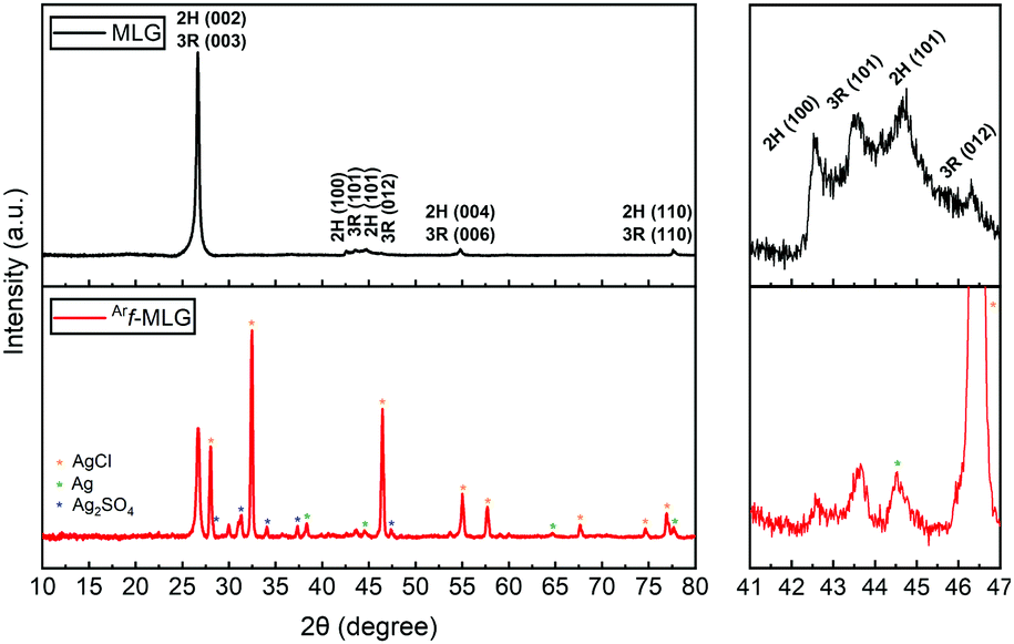 | ||
| Fig. 7 XRD spectra of MLG (top) and Arf-MLG (bottom) in the range between 2θ = 10° and 80° (left) and expanded section in the range between 2θ = 41° and 47° (right). The * denote lines associated with silver compounds (see text for details) | ||
Many additional diffraction lines are present within the spectrum of the Arf-MLG sample, suggesting other chemical species have been incorporated within the structure. The characteristic four-line pattern also appears to be present within this spectrum albeit the 2H (101) and 3R (012) lines are obscured by some new lines. This confirms that there is no significant change to the interlayer spacing upon functionalisation. As highlighted with asterisks (*), the majority of these correspond to the diffraction of the AgCl, Ag and Ag2SO4 impurities incorporated into the material (PDF card numbers: 00-006-0480,52 01-073-697753 and 01-074-173954). The presence of these silver compounds is in agreement with XPS data presented above. There are no observable lines at 2θ angles lower that 26.6° This suggests that largest interlayer spacing value between planes corresponds to the graphitic planes. Therefore, it is most likely that functionalisation has taken place at the outer surfaces of the material. Functionalisation within the internal MLG structure would, of course, result in an increase in the interlayer spacing. The lines corresponding to the 2H and 3R arrangements in both MLG and Arf-MLG show only minor differences confirming the functionalisation has only a small impact on the crystallinity and interlayer spacing of the MLG structure. Again, this is consistent with functionalisation at the outer positions only.
Analysis of surface morphology using SEM and TEM
Scanning electron microscopy (SEM) and transmission electron microscopy (TEM) were used to investigate the surface morphology and lateral dimensions of the graphitic sheets. Four SEM images were taken of a representative example of each material at low and high magnifications (Fig. 8 and 9). The images reveal that both materials consist of multi particulate material as agglomerates which range in diameter between 10–30 μm for MLG and <10 μm in size for Arf-MLG. The quantity of agglomerates within MLG exceeds that of Arf-MLG, suggesting that the functionalisation process has led these loosely bound aggregates to unravel. At lower magnifications MLG and Arf-MLG display a powder like appearance. At increased magnifications, it can be seen that these agglomerates are irregularly arranged consisting of flakes comprised of mostly multi-layered stacks, physically aggregated by π–π interactions. These stacks adopt wavy topography and curled edges. The non-uniform nature of the morphology of these materials is most evident in the higher resolution images. These defects are likely to result from the plasma ablation process during synthesis. The particle size distribution is due to the method of processing of this material. | ||
| Fig. 8 Representative SEM images for MLG at low and high magnifications. | ||
 | ||
| Fig. 9 Representative SEM images for Arf-MLG at low and high magnifications. | ||
Under the conditions utilised to record the images, it was found that the samples underwent charging. In order to obtain more enhanced images, gold coating was added using a sputter coater. The gold coating can be seen with a scaly appearance, as exemplified in Fig. 10.
 | ||
| Fig. 10 SEM image for Arf-MLG highlighting the scaly appearance. | ||
Additional SEM images of Arf-MLG are provided in Fig. 11. These highlight some of the features of the materials related to their porosity. As can be seen in the image on the left, there is a macro sized pore (circled) which contains some additional material. We believe that this could be some smaller flakes of Arf-MLG which become trapped within the in-plane pore, and for this reason are difficult to remove during the purification process. The presence of material which could be trapped silver nanomaterials can also be seen on an image in Fig. S7 (see ESI†). The image on the right of Fig. 11 highlights the slit like channels which are found within the spacing between subsequent stacks. The implications of these features on the surface area and porosity of the MLG and Arf-MLG materials are discussed in the following section.
 | ||
| Fig. 11 SEM images of Arf-MLG showing; a blocked macropore (left) and slit like channels (right). | ||
Selected TEM images of MLG and Arf-MLG are presented in Fig. 12. These also shown that both materials consist of multiple platelets with significant clumping. These multi-layered structures can be observed by differences in the contrast. Darker areas within the TEM images represent more dense areas within increased number of layers, whilst light areas represent those of less layers. It can be observed by TEM images that the stacks of layers exhibit lateral dimensions between 100–500 nm in diameter. As with the SEM images, they also indicate material which contains a broad range of morphologies across the surface of both materials.
 | ||
| Fig. 12 TEM images for MLG (a + b) and Arf-MLG (c + d). | ||
When comparing the SEM and TEM images for Arf-MLG with those of MLG, it can be concluded that there are no visual changes of major significance in the morphology upon functionalisation. Nevertheless, the orientation of stacks in Arf-MLG appear to be less agglomerated than those within MLG. This causes the individual stacks to appear much clearer within the SEM images. TEM images also reveal that the flakes remain very similar in size and distribution.
Surface area and porosity analysis
Nitrogen adsorption–desorption measurements were used to determine the surface area and pore size distribution of MLG and Arf-MLG, utilising Branauer–Emmett–Teller (BET) analysis and Barret–Joyner–Halenda (BJH) analysis.55 The results of these investigations are presented in Fig. 13. It was found that MLG and Arf-MLG both exhibited Type IIb N2 adsorption–desorption isotherms typical of materials composed of plate-like particles (Fig. 13a).56 A Type H3 hysteresis loop is present in each isotherm, indicating the occurrence of capillary condensation within pores of ∼4 nm in size.57 Hysteresis of this type is usually associated with plate-like aggregates or adsorbents containing slit-like pores. | ||
| Fig. 13 BET data for MLG and Arf-MLG including: (a) N2 adsorption–desorption isotherm (b) pore size distribution as a function of incremental pore volume (c) pore size distribution as a function of incremental pore area. | ||
MLG and Arf-MLG were found to exhibit BET surface areas corresponding to 380.22 and 192.13 m2g−1, respectively (Table 2). A significant contribution of this area originates from pores between 1.7–300 nm. These pores are mostly present within the space between neighbouring stacks which correspond to 75.5% (MLG) and 87.4% Arf-MLG of the total surface area.
| MLG | Ar f-MLG | |
|---|---|---|
| BET surface area (m2 g−1) | 380.22 | 192.13 |
| BJH adsorption cumulative surface area of pores between 1.7–300 nm (m2 g−1) | 287.01 | 167.86 |
| Percentage contribution of pores between 1.7–300 nm to the total BET surface area (%) | 75.50 | 87.40 |
| BJH desorption average pore width (4V/A) (nm) | 9.53 | 11.70 |
The pore size distribution profile was examined by plotting the pore size distribution as a function of incremental pore volume (Fig. 13b) and incremental pore area using the adsorption branch of the isotherm (Fig. 13c). Overall, the curves reveal similar patterns for both MLG and Arf-MLG in each plot, suggesting a minor impact to the overall structure upon functionalisation. In parallel, the average pore size for MLG and Arf-MLG were 9.53 nm and 11.70 nm, respectively. The main difference, however, is a decrease in the area and volume of pores affecting mostly pores with diameters of less than ∼75 nm. This is an indication that functionalisation causes a significant reduction in the quantity of pores within the mesoporous region. This finding coincides with the significant decrease in BET surface area (almost half of MLG). We suggest that the functionalised sheets re-orientate themselves to adopt curled, scroll-like edges due to enhanced interactions between the functionalised stacks.
With such a situation, many of the slit-like pores and channels between neighbouring stacks would become inaccessible to the nitrogen adsorbent molecules. In addition, upon functionalisation, we also observe blockage of pores with smaller aggregates (as seen in Fig. 11). This is can be clearly seen in the SEM image in Fig. 11a which shows a macropore with a width of 700 nm in addition to Fig. 11b where stacks of sheets can be observed.58
Experimental
General remarks
All solvents and reagents were purchased from commercial suppliers and used with no further purification. The MLG material was synthesised and provided by Perpetuus Carbon Technologies.:1), followed by the addition of K2S2O8 (0.266 g, 9.85 × 10⁻⁴ mol) and AgNO3 (0.027 g, 1.60 × 10⁻⁴ mol). The mixture was allowed to stir for 44 h at room temperature. The biphasic mixture was filtered and the DCM layer was separated from the filtrate using a separating funnel. The DCM layer was then evaporated to dryness to give a yellow oil consisting of two compounds: 4,4′-bis(trifluoromethyl)biphenyl (A) and bis((trifluoromethyl)-diphenyl)ether (B). Characterisation of A: 1H NMR δ (CD3CN): 7.87 (d, 3JHH = 8.2 Hz, 4H), 7.81 (d, 3JHH = 8.2 Hz, 4H). 19F NMR δ (CD3CN): −63.06. EI-MS m/z [M]+ calc. for C14H8F6 290 Da: found: 290 Da. Characterisation of B: 1H NMR δ (CD3CN): 7.72 (d, 3JHH = 8.2 Hz, 4H), 7.20 (d, 3JHH = 8.2 Hz, 4H). 19F NMR δ (CD3CN): −62.42. EI-MS m/z [M]+ calc. for C14H8F6O 306 Da: found 306 Da.
:1) followed by the addition of K2S2O8 (2.600 g, 9.62 × 10⁻³ mol) and AgNO3 (1.180 g, 7.00 × 10⁻³ mol). The mixture was allowed to stir for 44 h at room temperature. The reaction mixture was then centrifuged and the resultant Arf-MLG solid was separated and washed repeatedly with water, acetonitrile, and DCM through several dispersion/centrifugation cycles (4000 rpm, 20 min). The resultant Arf-MLG was dried under vacuum (10−6 bar) for 1 week, to remove any residual solvents and traces of volatile components A and B.
:1). The mixture was allowed to stir for 44 h at room temperature. The reaction mixture was then centrifuged and the resultant cOx-MLG solid was separated and washed repeatedly with water, acetonitrile, and DCM through several dispersion/centrifugation cycles. The resultant material was dried in vacuum for 1 week.
Characterisation methods
X-Ray photoelectron spectroscopy (XPS) analysis was performed using a Kratos Axis Ultra-DLD photoelectron spectrometer with a monochromatic Al Kα electron source (1486.6 eV). XPS data was analysed using CasaXPS and binding energies were referenced to carbon core level for adventitious carbon at 284.8 eV possessing an uncertainty of ∼0.2 eV. Curve fitting was carried out using Gaussian and Lorentzian line profiles.Thermal gravimetric analysis (TGA) was carried out using a PerkinElmer TGA 4000 instrument. The samples were heated from room temperature up to 900 °C (5 °C min−1) under a nitrogen atmosphere (50 mL min−1).
Raman spectroscopy was performed using a Renishaw inVia confocal Raman microscope equipped with an Ar+ visible green laser with an emission wavelength of 514 nm. Spectra were collected in a reflective mode by a high sensitive charge couple device (CCD) detector.
Powder X-ray diffraction (XRD) patterns were collected using a Panalytical X’Pert diffractometer with a Cu anode irradiation (λ = 1.541 Å) operating at 40 kV and 40 mA. Phase identification was performed by matching experimental patterns against entries in the ICDD standard database.
Scanning electron microscopy (SEM) images were obtained using a Zeiss Supra 35VP (FEG) SEM instrument. The samples were gold-coated using a sputtering coater to enhance the resolution of the images.
Transmission electron microscopy (TEM) images were obtained using a Jeol 2100 field emission gun (FEG) TEM with a 200 kV power source.
The surface area and porosity characteristics of the materials were analysed using a Micromeritics ASAP 2020 physisorption analyser. Samples were degassed under 0.667 Pa for 720 minutes at 150 °C with a heating rate of 10 min−1. The surface area and pore size distribution were measured at 77 K using Brunauer Emmett Teller (BET) and Barrett Joyner Halenda (BJH) cumulative pore volume methods, respectively.
1H and 19F NMR spectra were performed on a Bruker 400 MHz Ascend™ 400, which operated at 400 MHz for 1H nuclei and 376.6 MHz for 19F nuclei. Chemical shifts are reported in parts per million (ppm). NMR spectra were obtained in CD3CN solvent (1.93 ppm) and internal reference for 19F.
Mass spectrometry (MS) was carried out on compounds A and B using a Thermoscientific ISQ Single quad with direct insertion probe and the identity of the compounds were confirmed for the preinstalled library of compounds.
Conclusions
In this article, we provide a preliminary account outlining the successful covalent functionalisation of MLG with 4-(trifluoromethyl)phenyl radicals. This has been achieved by using 4-(trifluoromethyl)phenyl boronic acid as a radical source utilising Baran's protocol. The newly formed material, Arf-MLG, was found to be decorated at a number of positions at the outer surface as confirmed by a number of spectroscopic and analytical techniques.At this stage of the development, some challenges associated with this functionalisation methodology and the nature of the plasma-synthesised multi-layer graphitic material have been identified. The attachment of 4-(trifluoromethyl)phenyl moieties is accompanied by an increase in oxygen functionality around the outer surfaces of the MLG stacks, as a result of the oxidising conditions. Furthermore, the task of removal of entrapped impurities, particularly silver in this case, will need to be addressed. Nevertheless, early indications suggest that this approach could provide access to aryl radicals in a cost-effective and safer alternative to hazardous diazonium salts. As a result, this methodology could offer a novel safer approach to synthesise functionalised MLG materials on a larger scale with potential to be developed industrially. We are currently investigating ways in which this methodology can be optimised for practical application and exploring other derivatives. This may assist further processing and provide enhanced interaction with other materials. The development of new functionalisation strategies on commercially derived graphitic materials, of course, becomes increasingly important applications across materials science.
Conflicts of interest
There are no conflicts to declare.Acknowledgements
This work was funded by European Social Fund (ESF) via the Welsh Government through a KESS2 PhD studentship for R. M. It was co-sponsored by Perpetuus Carbon Technologies. The company is also thanked for providing the raw MLG material. We are also grateful to Dr Gregg Shaw (Cardiff University) and the HarwellXPS EPSRC National Facility for X-Ray Photoelectron Spectroscopy Service for carrying out the Raman, XPS and TGA data collections and helpful discussions. We are additionally grateful to Dr Uchechukwu K. Onwukwe, Dr Ashley Howkins and Dr Lorna Anguilano at the Experimental Techniques Centre, Brunel University London, for running SEM and TEM analysis.References
- K. S. Novoselov, A. K. Geim, S. V. Morozov, D. Jiang, Y. Zhang, S. V. Dubonos, I. V. Grigorieva and A. A. Firsov, Electric Field Effect in Atomically Thin Carbon Films, Science, 2004, 306, 666–669 CrossRef CAS.
- Y. Zhu, H. Ji, H.-M. Cheng and R. S. Ruoff, Mass production and industrial applications of graphene materials, Natl. Sci. Rev., 2018, 5, 90–101 CrossRef CAS.
- P. Bazylewski and G. Fanchini, Comprehensive Nanoscience and Nanotechnology, Elsevier, 2019, vol. 1, pp. 287–304 Search PubMed.
- L. Lin, H. Peng and Z. Liu, Synthesis challenges for graphene industry, Nat. Mater., 2019, 18, 520–524 CrossRef CAS.
- D. W. Johnson, B. P. Dobson and K. S. Coleman, A manufacturing perspective on graphene dispersions, Curr. Opin. Colloid Interface Sci., 2015, 20, 367–382 CrossRef CAS.
- A. P. Kauling, A. T. Seefeldt, D. P. Pisoni, R. C. Pradeep, R. Bentini, R. V. B. Oliveira, K. S. Novoselov and A. H. Castro Neto, The Worldwide Graphene Flake Production, Adv. Mater., 2018, 30, 1–6 CrossRef.
- V. Georgakilas, M. Otyepka, A. B. Bourlinos, V. Chandra, N. Kim, K. C. Kemp, P. Hobza, R. Zboril and K. S. Kim, Functionalization of Graphene: Covalent and Non-Covalent Approaches, Derivatives and Applications, Chem. Rev., 2012, 112, 6156–6214 CrossRef CAS.
- G. H. Yang, D. D. Bao, H. Liu, D. Q. Zhang, N. Wang and H. T. Li, Functionalization of Graphene and Applications of the Deriviatives, J. Inorg. Organomet. Polym., 2017, 27, 1129–1141 CrossRef CAS.
- B. J. Hong, O. C. Compton, Z. An, I. Eryazici and S. T. Nguyen, Successful Stabilization of Graphene Oxide in Electrolyte Solutions: Enhancement of Biofunctionalization and Cellular Uptake, ACS Nano, 2012, 6, 63–73 CrossRef CAS.
- S. Niyogi, E. Bekyarova, M. E. Itkis, H. Zhang, K. Shepperd, J. Hicks, M. Sprinkle, C. Berger, C. N. Lau, W. A. DeHeer, E. H. Conrad and R. C. Haddon, Spectroscopy of Covalently Functionalized Graphene, Nano Lett., 2010, 10, 4061–4066 CrossRef CAS.
- J. M. Englert, C. Dotzer, G. Yang, M. Schmid, C. Papp, J. M. Gottfried, H.-P. Steinrück, E. Spiecker, F. Hauke and A. Hirsch, Covalent bulk functionalization of graphene, Nat. Chem., 2011, 3, 279–286 CrossRef CAS.
- H. Liu, S. Ryu, Z. Chen, M. L. Steigerwald, C. Nuckolls and L. E. Brus, Photochemical Reactivity of Graphene, J. Am. Chem. Soc., 2009, 131, 17099–17101 CrossRef CAS.
- C. K. Chua and M. Pumera, Friedel–Crafts Acylation on Graphene, Chem. – Asian J., 2012, 7, 1009–1012 CrossRef CAS.
- T. A. Strom, E. P. Dillon, C. E. Hamilton and A. R. Barron, Nitrene addition to exfoliated graphene: a one-step route to highly functionalized graphene, Chem. Commun., 2010, 46, 4097–4099 RSC.
- S. Sarkar, E. Bekyarova, S. Niyogi and R. C. Haddon, Diels− Alder chemistry of graphite and graphene: graphene as diene and dienophile, J. Am. Chem. Soc., 2011, 133, 3324–3327 CrossRef CAS.
- H. Xu and K. S. Suslick, Sonochemical Preparation of Functionalized Graphenes, J. Am. Chem. Soc., 2011, 133, 9148–9151 CrossRef CAS.
- H. Ismaili, D. Geng, A. X. Sun, T. T. Kantzas and M. S. Workentin, Light-Activated Covalent Formation of Gold Nanoparticle–Graphene and Gold Nanoparticle–Glass Composites, Langmuir, 2011, 27, 13261–13268 CrossRef CAS.
- X. Zhong, J. Jin, S. Li, Z. Niu, W. Hu, R. Li and J. Ma, Arynecycloaddition: highly efficient chemical modification of graphene, Chem. Commun., 2010, 46, 7340–7342 RSC.
- S. Mahouche-Chergui, S. Gam-Derouich, C. Mangeney and M. M. Chehimi, Aryl diazonium salts: a new class of coupling agents for bonding polymers, biomacromolecules and nanoparticles to surfaces, Chem. Soc. Rev., 2011, 40, 4143–4166 RSC.
- G. L. C. Paulus, Q. H. Wang and M. S. Strano, Covalent Electron Transfer Chemistry of Graphene with Diazonium Salts, Acc. Chem. Res., 2013, 46, 160–170 CrossRef CAS.
- P. Huang, H. Zhu, L. Jing, Y. Zhao and X. Gao, Graphene Covalently Binding Aryl Groups: Conductivity Increases Rather than Decreases, ACS Nano, 2011, 5, 7945–7949 CrossRef CAS.
- A. Wang, W. Yu, Z. Huang, F. Zhou, J. Song, Y. Song, L. Long, M. P. Cifuentes, M. G. Humphrey, L. Zhang, J. Shao and C. Zhang, Covalent functionalization of reduced graphene oxide with porphyrin by means of diazonium chemistry for nonlinear optical performance, Sci. Rep., 2016, 6, 23325, DOI:10.1038/srep23325.
- E. Bekyarova, M. E. Itkis, P. Ramesh, C. Berger, M. Sprinkle, W. A. de Heer and R. C. Haddon, Chemical Modification of Epitaxial Graphene: Spontaneous Grafting of Aryl Groups, J. Am. Chem. Soc., 2009, 131, 1336–1337 CrossRef CAS.
- R. Sharma, J. H. Baik, C. J. Perera and M. S. Strano, Anomalously large reactivity of single graphene layers and edges toward electron transfer chemistries, Nano Lett., 2010, 10, 398–405 CrossRef CAS.
- Z. Xia, F. Leonardi, M. Gobbi, Y. Liu, V. Bellani, A. Liscio, A. Kovtun, R. Li, X. Feng, E. Orgiu, P. Samorì, E. Treossi and V. Palermo, Electrochemical Functionalization of Graphene at the Nanoscale with Self-Assembling Diazonium Salts, ACS Nano, 2016, 10, 7125–7134 CrossRef CAS.
- C. Peng, Y. Xiong, Z. Liu, F. Zhang, E. Ou, J. Qian, Y. Xiong and W. Xu, Bulk functionalization of graphene using diazonium compounds and amide reaction, Appl. Surf. Sci., 2013, 280, 914–919 CrossRef CAS.
- S. Rooyanian, M. Bagherzadeh, Z. Akrami and A. N. Golikand, A simple route to surface functionalization of graphene nanosheets by benzoic acid and its application toward Pb(ii) sensing, New J. Chem., 2018, 42, 17371–17378 RSC.
- M. Sheng, D. Frurip, D. Gorman and J. Loss, Reactive chemical hazards of diazonium salts, Prev. Process Ind., 2015, 38, 114–118 CrossRef CAS.
- I. Walters and D. Walters, Perpetuus Research & Development Limited, EU Pat., EP3129323B1, 2019 Search PubMed.
- M. S. D. C. Dela Vega and M. R. Vasquez Jr, Plasma-functionalized exfoliated multilayered graphene as cement reinforcement, Composites, Part B, 2019, 160, 573–585 CrossRef CAS.
- A. Dickschat and A. Studer, Radical Addition of Arylboronic Acids to Various Olefins under Oxidative Conditions, Org. Lett., 2010, 12, 3972–3974 CrossRef CAS.
- I. B. Seiple, S. Su, R. A. Rodriguez, R. Gianatassio, Y. Fujiwara, A. L. Sobel and P. S. Baran, Direct C−H Arylation of Electron-Deficient Heterocycles with Arylboronic Acids, J. Am. Chem. Soc., 2010, 132, 13194–13196 CrossRef CAS.
- Y. Fujiwara, V. Domingo, I. B. Seiple, R. Gianatassio, M. Del Bel and P. S. Baran, Practical C−H Functionalization of Quinones with Boronic Acids, J. Am. Chem. Soc., 2011, 133, 3292–3295 CrossRef CAS.
- N. Uchiyama, E. Shirakawa, R. Nishikawa and T. Hayashi, Iron-catalyzed oxidative coupling of arylboronic acids with benzene derivatives through homolytic aromatic substitution, Chem. Commun., 2011, 47, 11671–11673 RSC.
- D. Liu, C. Liu, H. Li and A. Lei, Direct Functionalization of Tetrahydrofuran and 1,4-Dioxane: Nickel-Catalyzed Oxidative C(sp3)H Arylation, Angew. Chem., Int. Ed., 2013, 52, 4453–4456 CrossRef CAS.
- J. Y. Kim, S. Lee, T.-Y. Kim and H.-T. Kim, A Simple Diazonium Coupling Reaction Enhances Durability of Modified Graphitic Carbons Used as Catalyst Supports for Polymer Electrolyte Membrane Fuel Cell, Electrochim. Acta, 2014, 134, 418–425 CrossRef CAS.
- V. K. Kaushik, XPS core level spectra and Auger parameters for some silver compounds, J. Electron Spectrosc. Relat. Phenom., 1991, 56, 273–277 CrossRef CAS.
- J. C. Fuggle, E. Källne, L. M. Watson and D. J. Fabian, Electronic structure of aluminum and aluminum-noble-metal alloys studied by soft-X-ray and X-ray photoelectron spectroscopies, Phys. Rev. B: Solid State, 1977, 16, 750–761 CrossRef CAS.
- G. Zhang, M. Wen, S. Wang, J. Chen and J. Wang, Insights into thermal reduction of the oxidized graphite from the electro-oxidation processing of nuclear graphite matrix, RSC Adv., 2018, 8, 567–579 RSC.
- Y. Devrim and A. Albostan, Graphene-Supported Platinum Catalyst-Based Membrane Electrode Assembly for PEM Fuel Cell, J. Electron. Mater., 2016, 45, 3900–3907 CrossRef CAS.
- P.-G. Ren, D.-X. Yan, X. Ji, T. Chen and Z.-M. Li, Temperature dependence of graphene oxide reduced by hydrazine hydrate, Nanotechnology, 2011, 22(5), 055705 CrossRef.
- F. Tuinstra and J. L. Koenig, Raman Spectrum of Graphite, J. Chem. Phys., 1970, 53, 1126–1130 CrossRef CAS.
- M. A. Pimenta, G. Dresselhaus, M. S. Dresselhaus, L. G. Cançado, A. Jorio and R. Saito, Studying disorder in graphite-based systems by Raman spectroscopy, Phys. Chem. Chem. Phys., 2007, 9, 1276–1291 RSC.
- A. C. Ferrari and J. Robertson, Interpretation of Raman spectra of disordered and amorphous carbon, Phys. Rev. B: Condens. Matter Mater. Phys., 2000, 61, 14095–14107 CrossRef CAS.
- A. C. Ferrari, J. C. Meyer, V. Scardaci, C. Casiraghi, M. Lazzeri, F. Mauri, S. Piscanec, D. Jiang, K. S. Novoselov, S. Roth and A. K. Geim, Raman Spectrum of Graphene and Graphene Layers, Phys. Rev. Lett., 2006, 97, 187401 CrossRef CAS.
- V. T. Nguyen, H. D. Le, V. C. Nguyen, T. T. T. Ngo, D. Q. Le, X. N. Nguyen and N. M. Phan, Synthesis of multi-layer graphene films on copper tape by atmospheric pressure chemical vapor deposition method, Adv. Nat. Sci.: Nanosci. Nanotechnol., 2013, 4, 035012 Search PubMed.
- R. P. Vidano, D. B. Fischbach, L. J. Willis and T. M. Loehr, Observation of Raman band shifting with excitation wavelength for carbons and graphites, Solid State Commun., 1981, 39, 341–344 CrossRef CAS.
- D. C. Elias, R. R. Nair, T. M. G. Mohiuddin, S. V. Morozov, P. Blake, M. P. Halsall, A. C. Ferrari, D. W. Boukhvalov, M. I. Katsnelson, A. K. Geim and K. S. Novoselov, Control of Graphene's Properties by Reversible Hydrogenation: Evidence for Graphane, Science, 2009, 323, 610–613 CrossRef CAS.
- M. S. Seehra, U. K. Geddam, D. Schwegler-Berry and A. B. Stefaniak, Detection and quantification of 2H and 3R phases in commercial graphene-based materials, Carbon, 2015, 95, 818–823 CrossRef CAS.
- A. Bianco, H.-W. Cheng, T. Enoki, Y. Gogotsi, R. H. Hurt and N. Koratkar, All in the graphene family – A recommended nomenclature for two-dimensional carbon materials, Carbon, 2013, 65, 1–6 CrossRef CAS.
- K. S. Subrahmanyam, S. R. C. Vivekchand, A. Govindaraj and C. N. R. Rao, A study of graphenes prepared by different methods: characterization, properties and solubilization, J. Mater. Chem., 2008, 18, 1517–1523 RSC.
- H. E. Swanson, R. K. Fuyat and G. M. Ugrinic, Circular. Standard X-ray Diffraction Powder Patterns, 1955, vol. IV, 539, p. 44 Search PubMed.
- T. Barth and G. Lunde, Die Gitterkonstanten der Platinmetalle, Silber und Gold, Z. Phys. Chem., 1926, 121, 78–102 CAS.
- B. N. Mehrotra, T. Hahn, W. Eysel, H. Roepke and A. Illguth, Polymorphism of sodium sulfate, Na2SO4, Neues Jahrb. Mineral., Monatsh., 1978, 408–421 CAS.
- E. P. Barrett, L. G. Joyner and P. P. Halenda, The Determination of Pore Volume and Area Distributions in Porous Substances. I. Computations from Nitrogen Isotherms, J. Am. Chem. Soc., 1951, 73, 373–380 CrossRef CAS.
- F. Rouquerol, J. Rouquerol, K. S. W. Sing, G. Mourin and P. Llewellyn, Adsorption by Powders and Porous Solids, Elsevier, Amsterdam, 2nd edn, 2012 Search PubMed.
- M. Thommes, K. Kaneko, A. V. Neimark, J. P. Olivier, F. Rodriguez-Reinoso, J. Rouquerol and K. S. W. Sing, Physisorption of gases, with special reference to the evaluation of surface area and pore size distribution (IUPAC Technical Report), Pure Appl. Chem., 2015, 87, 1051–1069 CAS.
- K. S. W. Sing, Reporting physisorption data for gas/solid systems with special reference to the determination of surface area and porosity (Recommendations 1984), Pure Appl. Chem., 1985, 57, 603–619 CAS.
Footnote |
| † Electronic supplementary information (ESI) available: Containing further spectroscopic and analytical details concerning the characterisation of MLG and Arf-MLG. See DOI: 10.1039/d0nj04187d |
| This journal is © The Royal Society of Chemistry and the Centre National de la Recherche Scientifique 2020 |