DOI:
10.1039/C9NJ06287D
(Paper)
New J. Chem., 2020,
44, 5673-5683
Towards white light emission from a hybrid thin film of a self-assembled ternary samarium(III) complex†
Received
19th December 2019
, Accepted 7th February 2020
First published on 3rd March 2020
Abstract
A new samarium complex [Sm(hfaa)3(Py-Im)] (ML) was synthesized by utilizing hexafluoroacetylacetone (hfaa) and 2-(2-pyridyl)benzimidazole (Py-Im) as coordinating ligands. Single crystal X-ray analysis shows that in the solid-state the complex dimerizes through intermolecular hydrogen-bonding with N–H⋯O (2.127 Å) and N–H⋯F (2.576 Å) interactions. The complex in the solid-state displayed highly monochromatic brilliant red emission with Commission International de I’Eclairage (CIE) color coordinates of 0.6532; 0.3336, with a remarkably long luminescence lifetime (τexp. ≈ 204.47 ± 4.043 μs) and a high intrinsic quantum yield (QSmSm ≈ 6.60%). Furthermore, the complex in different organic media displayed color tunability from orange (CIE; 0.6071; 0.3568) to violet (CIE; 0.3634; 0.2144) with τexp. from 105.50 ± 0.143 to 14.27 ± 0.033 μs. Hybrid and flexible thin films obtained by doping different concentrations (1%, 2%, 4% and 6%) of the complex into the poly(urethane) (PU) polymer matrix also exhibited color tunability from violet (CIE; 0.3380; 0.2162) to light orange (CIE; 0.5666; 0.3408). White light emission from a 1% doped thin film of the complex was realized by changing the excitation wavelength. Thus, the new material could be a potential candidate for the fabrication of full-color display devices and for solid-state lighting (SSL) applications.
1. Introduction
Highly photoluminescent lanthanide (Ln) complexes incorporating organic ligands that utilize the antenna effect to generate efficient luminescent materials continue to be of interest to academics and industrialists because of their applications. A range of intriguing technological applications incorporating organo–lanthanide complexes has been developed such as organic light emitting diodes (OLEDs),1 laser materials,2 sensitizers to improve the electroluminescence (EL) of red and green emitting iridium complexes,1a,3 luminescent thermometers,4 or sensors.5 The extensive research efforts are due to the unique optical properties of trivalent lanthanide ions [Ln(III)], which feature fingerprint emissions for each Ln(III) ion spanning through the visible to near-infrared (NIR) region of the spectrum, exhibit highly monochromatic emissions, and have long-lived excited lifetimes. However, most of the work reported to date deals with either Eu(III) or Tb(III) that emits intense red and green light. Work related to luminescent Sm(III) complexes is very limited by comparison.
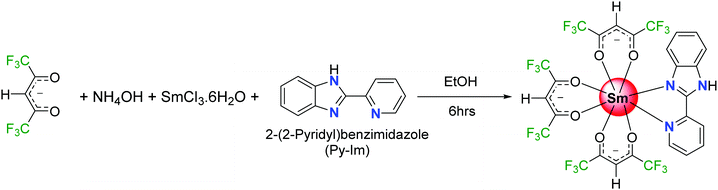
Generally, an efficient Sm(III) complex would display a deep red emission6 because of the presence of the electric-dipole 4G5/2 → 6H9/2 transition at 648 nm and thus is beneficial for constructing the red element in a full-color display. Moreover, the emission spectrum of Sm(III) ion displays two more medium intensity transitions at 563 nm (greenish-yellow emission) and 606 nm (yellowish-orange emission). The presence of these two medium intensity emission transitions in the spectrum offers emission color tunability; if the emission is not very efficient that would lead to residual ligand fluorescence (RLF) in the blue region of the spectrum. In fact, proper amalgamation of these colors in Sm(III) complex(es) could result in white light emission from a single molecule platform.7 This is achievable by change in concentration, excitation, temperature and solvent medium or by embedding the complex into a polymer matrix.7b,d,e Motivated by these ideas, and following on from some previous luminescence studies of Sm(III) hexafluoroacetylacetone complexes,8 we have synthesized a new ternary Sm(III) complex using hexafluoroacetylacetone (hfaa) as the primary antenna and 2-(2-pyridyl)benzimidazole (Py-Im) as the secondary ligand (Scheme 1). The primary hfaa ligand was chosen because of the presence of low vibrational bonds (C–F) that suppress radiationless transitions via vibrational relaxations.9 The bidentate secondary Py-Im ligand was chosen because of its compatible triplet state (3ππ* ≈ 20![[thin space (1/6-em)]](https://www.rsc.org/images/entities/char_2009.gif) 576 cm−1)1a and its asymmetrical N,N-chelating coordination mode via the five-membered imidazolyl nitrogen and the six-membered pyridyl nitrogen atoms, and thus could be useful in enhancing the radiative decay rate.10 Moreover, the NH proton of the imidazolyl ring is usually involved in hydrogen bond formation and self-assembly, resulting in fascinating structures and arrangements in the solid-state. The complex was characterized by analytical and spectroscopic methods and the solid-state structure was determined by single crystal X-ray diffraction (SC-XRD). It was found that NH proton in the complex contributes to the formation of a hydrogen bonded dimer in the solid-state, which is not common in this class of complexes.11 The photophysical properties of the complex were analyzed in detail by steady-state excitation and emission spectroscopy as well as by time-resolved spectroscopy in the solid-state and in different organic media (dichloromethane, acetonitrile, acetone, tetrahydrofuran, ethanol and methanol). The complex exhibits color tunability and shows a brilliant red emission in the solid-state with a remarkably long luminescence lifetime (τexp. ≈ 204.47 ± 4.043 μs) and an intrinsic quantum yield of QSmSm ≈ 6.60%. Upon changing the medium, the complex displays color tunability from orange to violet with an obvious change in the luminescence lifetime, thus hinting towards white light generation. Considering these interesting photophysical properties and the possibility of generating white light emission at a single component level, the complex was further embedded into a PU polymer matrix with different doping concentrations to develop color-tunable flexible hybrid thin films with a view to developing high-performance luminescent materials for optoelectronic application.
576 cm−1)1a and its asymmetrical N,N-chelating coordination mode via the five-membered imidazolyl nitrogen and the six-membered pyridyl nitrogen atoms, and thus could be useful in enhancing the radiative decay rate.10 Moreover, the NH proton of the imidazolyl ring is usually involved in hydrogen bond formation and self-assembly, resulting in fascinating structures and arrangements in the solid-state. The complex was characterized by analytical and spectroscopic methods and the solid-state structure was determined by single crystal X-ray diffraction (SC-XRD). It was found that NH proton in the complex contributes to the formation of a hydrogen bonded dimer in the solid-state, which is not common in this class of complexes.11 The photophysical properties of the complex were analyzed in detail by steady-state excitation and emission spectroscopy as well as by time-resolved spectroscopy in the solid-state and in different organic media (dichloromethane, acetonitrile, acetone, tetrahydrofuran, ethanol and methanol). The complex exhibits color tunability and shows a brilliant red emission in the solid-state with a remarkably long luminescence lifetime (τexp. ≈ 204.47 ± 4.043 μs) and an intrinsic quantum yield of QSmSm ≈ 6.60%. Upon changing the medium, the complex displays color tunability from orange to violet with an obvious change in the luminescence lifetime, thus hinting towards white light generation. Considering these interesting photophysical properties and the possibility of generating white light emission at a single component level, the complex was further embedded into a PU polymer matrix with different doping concentrations to develop color-tunable flexible hybrid thin films with a view to developing high-performance luminescent materials for optoelectronic application.
 |
| | Scheme 1 Synthesis of [Sm(hfaa)3(Py-Im)] complex. | |
2. Experimental section
2.1 Materials, syntheses and analyses
SmCl3·6H2O was purchased from Strem Chemicals, Inc. USA, while other chemicals were obtained from Sigma Aldrich and used as received. Solvents were pre-dried and distilled before use according to standard procedures.12 Elemental analysis was performed on Euro EA – CHN Elemental Analyser in the Department of Chemistry, Sultan Qaboos University. Attenuated total-reflectance (ATR) infrared (IR) spectra of pure solid samples were recorded on diamond using a Cary 630 FT-IR spectrometer. Mass spectra were obtained using a VG Autospec magnetic sector instrument using electrospray ionization (ESI).
2.2 Synthesis of the [Sm(hfaa)3(Py-Im)] ternary complex
The samarium complex was synthesized by a one-step reaction at room temperature (RT) (Scheme 1). To an ethanolic hfaa (0.73 g; 3.50 mmol) solution, 25% ethanolic ammonia (0.27 mL) solution was added dropwise with constant stirring. After the mixture was stirred for a further 30 min, ethanolic solutions of Py-Im (0.226 g, 1.16 mmol) and SmCl3·6H2O (0.422 g, 1.16 mmol) were added sequentially, and the reaction mixture was left with stirring for a further 6 h. The solution was left to allow slow solvent evaporation. After a week, a yellow powder precipitated. The precipitate was filtered, washed with ice-cold ethanol followed by hexane, and dried in the air to obtain a yellow solid in 65% yield. Calculated for C27H12F18N3O6Sm: C, 33.55; H, 1.25; N, 4.35; found C, 33.88; H, 1.20; N, 4.29%. ESI-MS – [M + K-(CH3)2CO]; m/z = 948.1; melting point (Tm) = 195 °C.
2.3 Single crystal X-ray diffraction analyses
A single crystal of [Sm(hfaa)3(Py-Im)] with dimensions of 0.77 × 0.57 × 0.43 mm was selected for X-ray diffraction. The intensity data was collected at 296 K on a STOE IPDS 2 diffractometer equipped with graphite monochromatic Mo-Kα radiation (λ = 0.71073 Å). The structure was solved by direct methods using SHELXT13 and refined by full-matrix least-squares methods on F2 using SHELXL17/1.14 All the hydrogen atoms were placed in calculated positions and refined using a riding model, with C–H = 0.93 Å for CH H-atoms, and Uiso(H) = 1.2Ueq(C). The N-bound H-atom was positioned geometrically (N–H = 0.86 Å) and refined with a riding model, with Uiso(H) = 1.2Ueq(N). The molecular geometry calculations and drawings were performed with Mercury for Windows15 and PLATON.16 WinGX17 was used to prepare material for publication. The crystal data, data collection and refinement parameters for [Sm(hfaa)3(Py-Im)] are presented in Table S1, CCDC 1943973.†
2.4 Hirshfeld surface analysis
Hirshfeld surface (HS) analysis (including fingerprint plots) was used to understand the interactions involved in the crystal packing. The Hirshfeld surface analysis18 and the associated two-dimensional fingerprint plots19 were generated using the CrystalExplorer17 package.20 The normalized contact distance (dnorm) was calculated via the following expression:| |  | (1) |
de and di are distances from a point on the surface to the nearest nucleus outside the HS and to the nearest nucleus inside the HS, respectively. rvdwi and rvdwe terms are the van der Waals radii of the atom, which lie inside the HS and outside of the HS, respectively. We employed the final validated CIF as the input to CrystalExplorer17 to conduct the above calculations for the samarium complex.
2.5 Hybrid thin film fabrication of [Sm(hfaa)3(Py-Im)]@PU_x%
A PU composite thin film of the [Sm(hfaa)3(Py-Im)] complex was fabricated by dissolving PU (4% w/v) in tetrahydrofuran (THF) (25 mL) The suspension was left with stirring at room temperature until a clear solution was observed. The solution of [Sm(hfaa)3(Py-Im)] in THF (5 mL) was added and the mixture was left with stirring overnight. The resulting solution was cast on glass Petri dishes and left for complete evaporation at 50 °C, which resulted in a transparent and smooth thin film.
2.6 Spectroscopic measurements
All spectroscopic measurements were performed at RT. The electronic spectra of free Py-Im and the complex were obtained on a Varian Cary 50 spectrophotometer in the 200–600 nm range. Excitation, emission spectra and decay curves of [Sm(hfaa)3(Py-Im)] complex and their respective hybrid thin films [Sm(hfaa)3(Py-Im)]@PU_x% were recorded on an Edinburgh FS5 fluorimeter. All decay curves were fitted to mono-exponential functions using the software supplied with the instrument.
3. Results and discussion
The new mixed-ligand complex [Sm(hfaa)3(Py-Im)] was synthesized using a one-pot method (Scheme 1) reported previously for the synthesis of analogous lanthanide complexes.1a The complex was characterized by elemental analysis, FT-IR spectroscopy and mass spectrometry. The complex is stable to air and moisture and is readily soluble in common organic solvents (except hexane and carbon tetrachloride). The ESI-MS spectrum of the complex in positive mode, in acetone, showed a molecular peak for the species [M + K-(CH3)2CO] with m/z value of 948.1 (Fig. S1, ESI†), confirming the presence of three hfaa and one Py-Im ligand consistent with the formulation of the complex shown in Scheme 1. The FTIR spectrum of the complex (Fig. S2, ESI†) displays strong absorption peak at 1672 cm−1 due to the C![[double bond, length as m-dash]](https://www.rsc.org/images/entities/char_e001.gif) O stretching vibration. The ν(CN + CC) and δ(N–H) vibrations of free Py-Im at 1592 and 1440 cm−1 are shifted to higher wavenumbers in the complex, demonstrating ligand coordination to the Sm(III) ion through imidazolic and pyridyl nitrogen atoms.1a Moreover, a broad absorption band (3300–2350 cm−1) with a peak at 3055 cm−1 due to a N–H stretching mode in the free Py-Im (Fig. S2, ESI†) appears as a relatively less strong sharp peak which could be beneficial in suppressing the photoluminescence (PL) quenching.
O stretching vibration. The ν(CN + CC) and δ(N–H) vibrations of free Py-Im at 1592 and 1440 cm−1 are shifted to higher wavenumbers in the complex, demonstrating ligand coordination to the Sm(III) ion through imidazolic and pyridyl nitrogen atoms.1a Moreover, a broad absorption band (3300–2350 cm−1) with a peak at 3055 cm−1 due to a N–H stretching mode in the free Py-Im (Fig. S2, ESI†) appears as a relatively less strong sharp peak which could be beneficial in suppressing the photoluminescence (PL) quenching.
3.1 Crystal structure of [Sm(hfaa)3(Py-Im)]
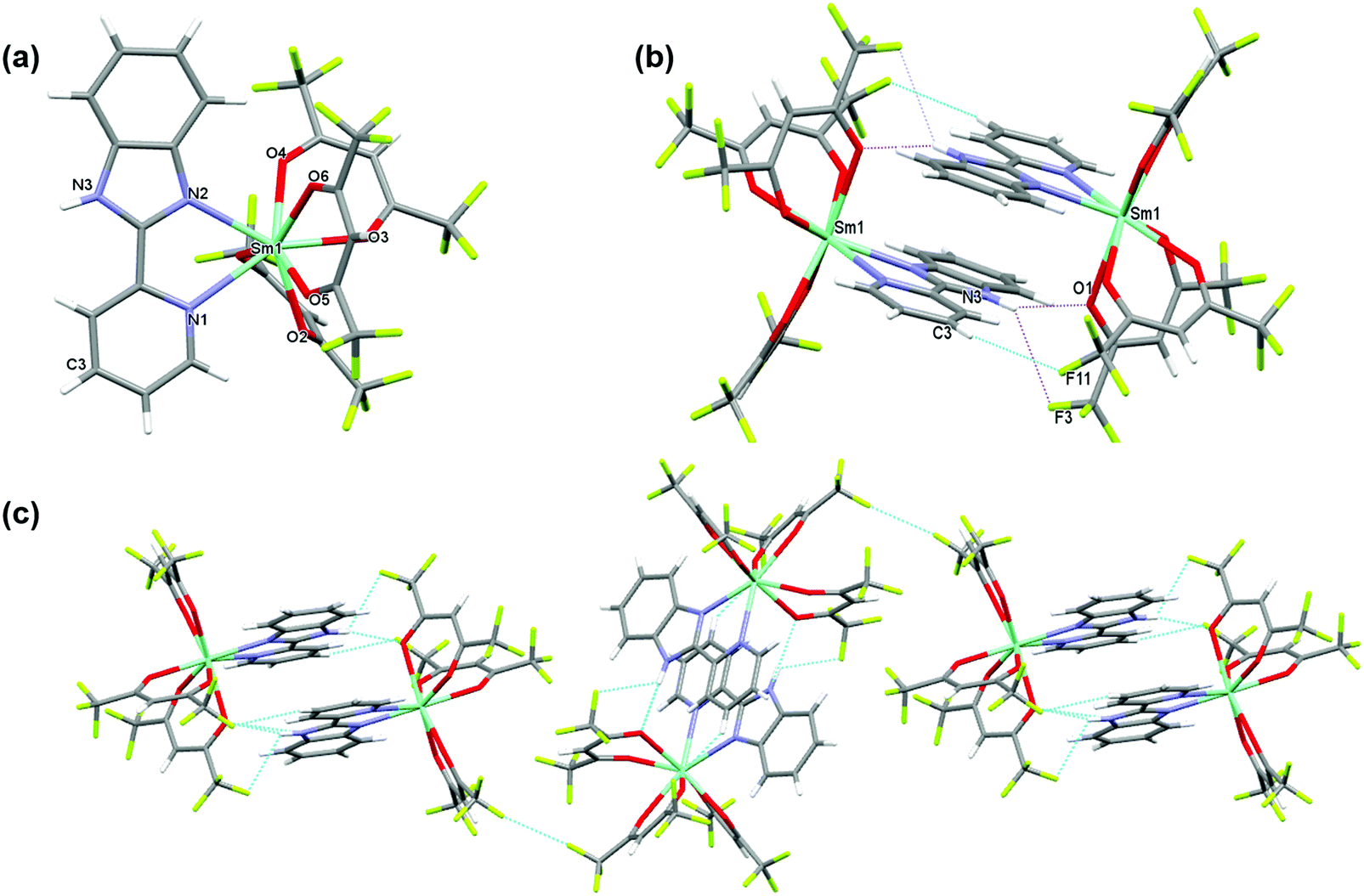
The complex crystallizes in the monoclinic space group P21/n with one independent [Sm(hfaa)3(Py-Im)] in the asymmetric unit (Fig. 1a). In the solid-state there is weak intermolecular hydrogen bonding that results in the dimerization of the structure through N–H⋯O (H(3)⋯O(1) 2.12 Å, N(3)⋯O(1) 2.920(6) Å, N(3)–H(3)⋯O(1) 153.8°) and N–H⋯F (H(3)⋯F(3) 2.58 Å, N(3)⋯F(3) 3.108(7) Å, N(3)–H(3)⋯F(3) 120.5°) hydrogen bonds as illustrated in Fig. 1b. The adjacent Sm(III) centers are separated by a distance of 8.160(1) Å. Each Sm(III) centers is in an 8-coordinate N2O6 environment with two nitrogen atoms from a Py-Im ligand and six oxygen atoms from three hfaa ligands. The coordination geometry of SmN2O6 is best described as a trigonal dodecahedron. The complex is isomorphous and isostructural with its recently published europium(III) analogue and displays a similar hydrogen bonding pattern.1a
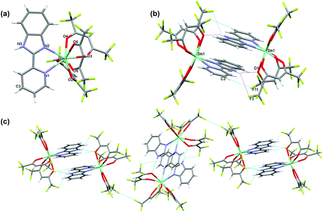 |
| | Fig. 1 (a) A view of the asymmetric unit of [Sm(hfaa)3(Py-Im)]2 and (b) comparative view of [Sm(hfaa)3(Py-Im)] represented via N–H⋯O and N–H⋯F intermolecular interactions. Dotted pink and blue lines depict the intermolecular interactions (c) packing diagram of the crystal exhibiting F⋯F interaction between hfaa ligands. | |
The metal–ligand distances are unremarkable. The Sm–O bond lengths vary from 2.349(3) to 2.454(3) Å with an average Sm–O bond length of 2.397 Å comparable to the reported Sm(III) complexes.21 The Sm–N1 and Sm–N2 bond lengths are 2.616(4) Å and 2.501(4) Å, respectively (Table S2, ESI†). This difference in the Sm–N bond lengths of 0.115 Å is similar to the difference in Eu–N bond lengths of 0.11 Å observed in the Eu analogue,1a and may be related to the bonding requirements of the Py-Im ligand that coordinates through the nitrogen atoms of linked 5- and 6-membered aromatic rings.
Beyond the dimeric assembly, intermolecular F⋯F interactions between the molecules occur (Fig. 1c). The detailed parameters of hydrogen bonds are given in (Table S3, ESI†). Furthermore, each molecule is linked by weak π–π stacking interactions [Cg1⋯Cg2i = 3.7460 (2) Å and Cg2⋯Cg3i = 3.7095 (2) Å; Cg1, Cg2 and Cg3 are the centroids of the N2/C6/N3/C7/C12, N1/C1–C5 and C7–C12 rings (Fig. S3, ESI†), respectively. The symmetry code is i = −x + 1, −y + 1, −z + 1], forming a 3-D structure.
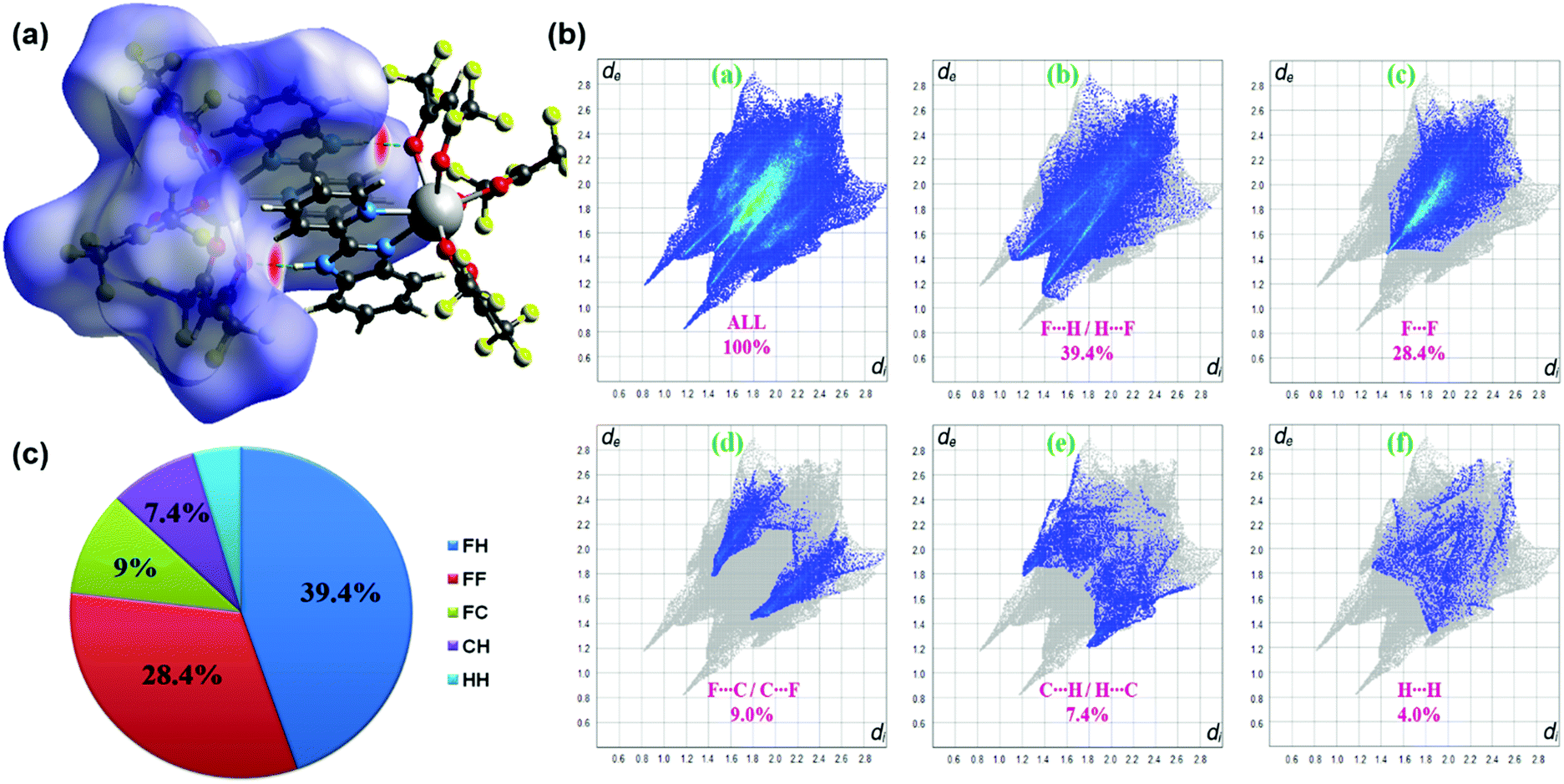
The three-dimensional Hirshfeld surface (HS) map generated for the complex is presented in Fig. 2a. Hirshfeld surface analysis is important in assessing the interactions in the crystal packing. In the maps in Fig. 2a, red areas are related to N–H⋯O intermolecular contacts. In the Hirshfeld surface maps, the contacts shown in red highlight the intermolecular interactions with distances shorter than the sum of the van der Waals radii.18 2D fingerprint plots (FPs) have been obtained from the Hirshfeld surface (HS) by plotting the fraction of points on the surface as a function of (de, di). Herein, de and di represent the distances from a point on the HS to the nearest atoms outside and inside the surface, respectively. F⋯H/H⋯F, F⋯F, F⋯C/C⋯F, C⋯H/H⋯C and H⋯H interactions exist in the FPs of complex (Fig. 2b). The F⋯H/H⋯F contacts represent the largest relative contribution, amounting to 39.4% in the complex (appearing as two narrow long spikes). The C⋯H/H⋯C contacts (7.4%) appear as two broad short spikes. Because of the replacement of CH3 groups by CF3 groups in the ligands, compared to other studies in the literature,2c,22 in this complex, the contribution of H⋯H interactions (4%) to the total HS is quite low.
 |
| | Fig. 2 (a) The dnorm-mapped Hirshfeld surface for visualizing the intermolecular contacts for the complex (b) 2D fingerprint plots and (c) π-chart for complex showing the percentage contribution of interactions. | |
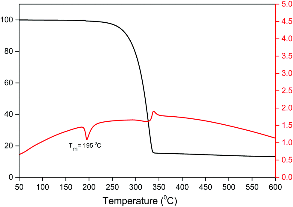
3.2 Thermal analysis
An important factor for the use of lanthanide-based hybrid materials in optoelectronic devices is their high thermal stability. The thermal stability of the Sm(III) complex was determined simultaneously by thermogravimetric analysis (TGA) and differential thermal analysis (DTA) as shown in Fig. 3. The thermogram exhibits a one-step weight loss due to the removal of the coordinated organic ligands (hfaa and Py-Im) with the decomposition temperature (Td) ≈ 224 °C. The DTA curve shows one sharp endothermic peak at 195 °C representing the melting point (Tm) of the complex. The high Td and Tm of the complex could be attributed to the hydrogen bonding and π–π stacking interactions in the complex in the solid-state. Moreover, the thermogram does not show any weight loss in the region 50–180 °C implying that it has no coordinated water/solvent molecules confirming the results of IR spectroscopic study.
 |
| | Fig. 3 TGA/DTA curve of the complex under N2 atmosphere. | |
3.3 Photophysical properties
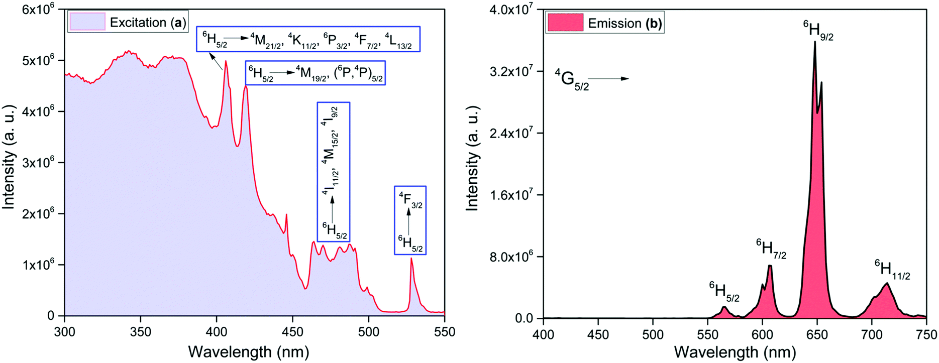
For strongly luminescent lanthanide complexes, the coordinated ligand(s) need to have some necessary prerequisites, namely; a strong light absorption properties that would result in strong light absorbing complexes and appropriate energy differences (ΔE)23 between the 3π–π* states of the coordinated organic ligand(s) and the emitting levels of Ln(III) ions. In order to check the first requirement, the electronic spectra of the free Py-Im ligand and the complex were recorded in DCM (Fig. S4, ESI†). The spectrum of the free Py-Im displays an intense absorption at 310 nm.1a The spectrum of the complex exhibits overlapping absorption bands of the Py-Im and hfaa with maxima at 298 nm with molar absorption coefficient 6.49 × 10⁴ M−1 cm−1 suggesting that the complex has strong light absorbing capability and hence potential for efficient PL. For the second parameter in the present complex, ΔE was calculated from the 3π–π* transition of the organic ligand(s) coordinated (3π–π* ≈ 21930 cm−1 for hfaa24 and 20576 cm−1 for Py-Im,1a respectively) to the central Sm(III) ion. The trivalent samarium ion has three potential excited states 4G5/2 (≈17924 cm−1), 4F3/2 (≈18332 cm−1) and 4G7/2 (≈20014 cm−1), respectively that can receive energy from 3π–π* states of the organic ligands.25 It is generally believed that after receiving energy from the 3π–π* states, the energy is transferred to 4G7/2 and 4F3/2 which finally relax the absorbed energy to 4G5/2 state, which in turn, undergoes radiative processes leading to emission from 4G5/2 state.26 The values of ΔE(3π–π*–4G5/2), ΔE(3π–π*–4F3/2) and ΔE(3π–π*–4G7/2) are 4006, 3598 and 1916 cm−1, respectively for hfaa while 2652, 2244 and 562 cm−1, respectively, for Py-Im. These energy differences suggest that the present complex should display strong emission at RT. In view of this we first analyzed the steady-state excitation and emission spectra as shown in Fig. 4. The excitation spectrum of the complex was obtained by monitoring the most intense emission transition appearing at 648 nm in the emission spectrum of the complex. The excitation spectrum in the 300–550 nm exhibits broadband and some intra-configurational transitions as shown in Fig. 4a at 406 nm, 418 nm, 477 nm and 527 nm, and are assigned27 to 4M21/2, 4K11/2, 6P3/2, 4F7/2, 4L13/2 ← 6H5/2, 4M19/2, (6P,4P)5/2 ← 6H5/2, 4I11/2, 4M19/2, 4I9/2 ← 6H5/2 and 4F3/2 ← 6H5/2, respectively.
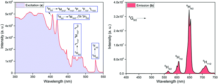 |
| | Fig. 4 Solid-state (a) excitation spectrum monitored at λem ≈ 648 nm and (b) corrected emission spectrum of the complex monitored at λex ≈ 374 nm at RT. | |
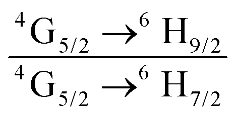
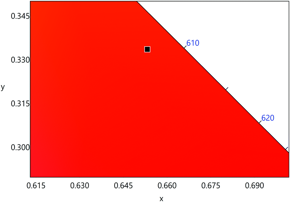
The emission spectrum of the complex at RT was obtained by choosing an excitation wavelength from the excitation spectrum to maximize the emission. The spectrum displays four well-resolved emission transitions at 564 nm, 605 nm, 648 nm and 714 nm, which are assigned to 4G5/2 → 6H5/2 (forbidden transition), 4G5/2 → 6H7/2 (magnetic dipole (MD) transition), 4G5/2 → 6H9/2 (electric dipole (ED) transition) and 4G5/2 → 6H11/2 (forbidden transition), respectively (Fig. 4b). Out of the four emission transitions in the spectrum, ED 4G5/2 → 6H9/2 hypersensitive transition dominates with the full width at half maxima (FWHM) ≈ 11.83 nm (Table 1) followed by the MD transition. It is well-established that the ratio (RLn) of the corrected ED to MD emission transition gives clues regarding the coordination symmetry and polarizability of the local environment around the Ln(III) ion in a given complex i.e., RSm = ED(4G5/2 → 6H9/2)/MD(4G5/2 → 6H7/2). The higher intensity of the ED transition and high RSm value of 6.00 for the present complex suggests a low molecular symmetry of the coordination sphere and that Sm(III) ion in the complex sits in a highly polarizable environment. The RSm value is comparable to values reported for similar Sm(III) complexes.2c,8a It worth noting that there is no residual ligand fluorescence in the 400–500 nm range suggesting that the energy absorbed by the organic ligands is efficiently transferred to Sm(III) emitting state as can be seen in Fig. 4b and colorful emission spectrum in Fig. S5, ESI,† as expected by the energy gap law. To get information about the emitted color from the solid complex, the CIE color coordinates (x;y) were calculated from the steady-state emission spectrum and the results are summarized in Table 1. As can be seen from the magnified CIE color diagram in Fig. 5, the complex emits intense red emission with color coordinates x = 0.6532; y = 0.3336, which are similar to National Television System Committee (NTSC) (x = 0.67; y = 0.33). It is important to emphasize that there are only few reported [Sm(β-diket.)3(ancillary ligand)] complexes that display an intense red emission.6,8a,b
Table 1 Photophysical parameters of the complex in different media at RT
| Medium |
FWHMa (nm) |
R
Sm
|
τ
exp.(μs) |
CIE (x; y) |
Color |
Q
SmSmc (%) |
FWHM of 4G5/2 → 6H9/2 ED transition.
Ratio of corrected emission intensity of ED to MD transition, i.e.,  . .
 . .
|
| Solid-state |
11.83 |
6.00 |
204.47 ± 4.043 |
0.6532; 0.3336 |
Brilliant red |
6.60 |
| DCM |
12.25 |
2.75 |
105.50 ± 0.143 |
0.6071; 0.3568 |
Orange |
3.40 |
| ACN |
11.13 |
2.70 |
42.75 ± 0.055 |
0.5607; 0.3167 |
Dark-coral |
1.37 |
| Acetone |
7.61 |
2.80 |
37.80 ± 0.187 |
0.4347; 0.2328 |
Rose-pink |
1.22 |
| THF |
6.55 |
2.47 |
35.01 ± 0.187 |
0.3451; 0.2355 |
Light-violet |
1.13 |
| EtOH |
7.96 |
2.20 |
20.39 ± 0.041 |
0.4409; 0.2623 |
Pale pink |
0.65 |
| MeOH |
8.02 |
2.39 |
14.27 ± 0.033 |
0.3634; 0.2144 |
Violet |
0.46 |
 |
| | Fig. 5 A magnified view of the CIE color diagram showing the intense red emission from the complex in the solid-state at RT. | |
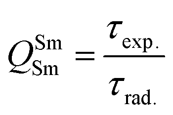
In addition to the steady-state emission, we also carried out the time-resolved PL decay dynamics. The PL lifetime (τexp) of the complex in the solid-state was measured at RT (Fig. S6 (ESI†) and Table 1) by monitoring the emission decay curve within 4G5/2 → 6H9/2 transition at 648 nm. The decay curve fits very well with mono-exponential behavior, indicating the presence of only emitting Sm(III) center in the solid-state. The complex displays remarkably long τexp. ≈ 204.47 ± 4.043 μs, which could be attributed to optimum ΔE between Sm(III) emitting state and prime hfaa and ancillary Py-Im ligands. Furthermore, the minimization of high energy oscillator strength of the N–H by intermolecular interactions i.e., N—H⋯O and N—H⋯F as shown in Fig. 1b and was complimented by the FTIR results, which show a relatively less strong sharp peak for N–H oscillator (Fig. S2, ESI†). Moreover, as determined by HS maps, the F⋯H/H⋯F largest relative contribution, amounting to 39.4% in the present complex further diminishes the role of another high energy oscillator enhancing the PL lifetime. Thus, HS analysis and 2-D fingerprint were very useful for understanding the contribution of intermolecular interactions in determining the PL properties. The PL lifetime of the present complex is higher than most of the known highly efficient [Sm(β-diket.)3(ancillary ligand)] complexes such as [Sm(hfaa)3(TPPO)2] ≈ 97 μs,8a [Sm(hfaa)3(phen)2] ≈ 37 μs8a and 54–56 μs,6 [Sm2(BTP)3(phen)2] ≈ 100 μs,28 [Sm(hfaa)3(tBu-xantpo)] ≈ 150 μs8c and is lower only two longest and efficient complexes [Sm(hfaa)3(pybox)] ≈ 390 μs8b and [Sm(hfaa)3(dpepo)] ≈ 280 μs8c until now, where TPPO = triphenylphosphine oxide; phen = 1,10-phenanthroline; BTP = 1,3-bis(4,4,4-trifluoro-1,3-dioxobutyl)phenyl; pybox = bis(oxazolinyl)pyridine; dpepo = bis[(2-diphenylphosphoryl)phenyl] ether; tBu-xantpo = 4,5-bis(di-tert-butylphosphoryl)-9,9-dimethylxanthene. The intrinsic quantum yield (QSmSm) of the complex is calculated by the following general expression 2 and the obtained data is summarized in Table 1:
| |  | (2) |
where
τrad is the calculated natural radiative lifetime of Sm(
III) ion (3100 μs) reported in the literature.
29
3.4 Effect of medium on PL properties and color.
ΔE between the emitting level and the next lower energy level in Sm(III) is ≈ 7400 cm−1.30 Therefore PL quenching is inevitable by the high energy oscillators (O–H ∼ 3300–3500 cm−1, N–H ∼ 3100–3300 cm−1 and C–H ∼ 2950 cm−1)31 of the solvents as well as oscillators within the coordinated ligands. In order to see the effect of the different solvents on the PL properties of the complex, we first analyzed the excitation spectra in different solvents. The excitation spectra in different solvents were obtained as discussed above and are shown in Fig. S7, ESI.† The spectra displayed broadband between 310–380 nm with the obvious change in intensity and follows the trend: DCM > ACN > Acetone > THF > EtOH > MeOH.
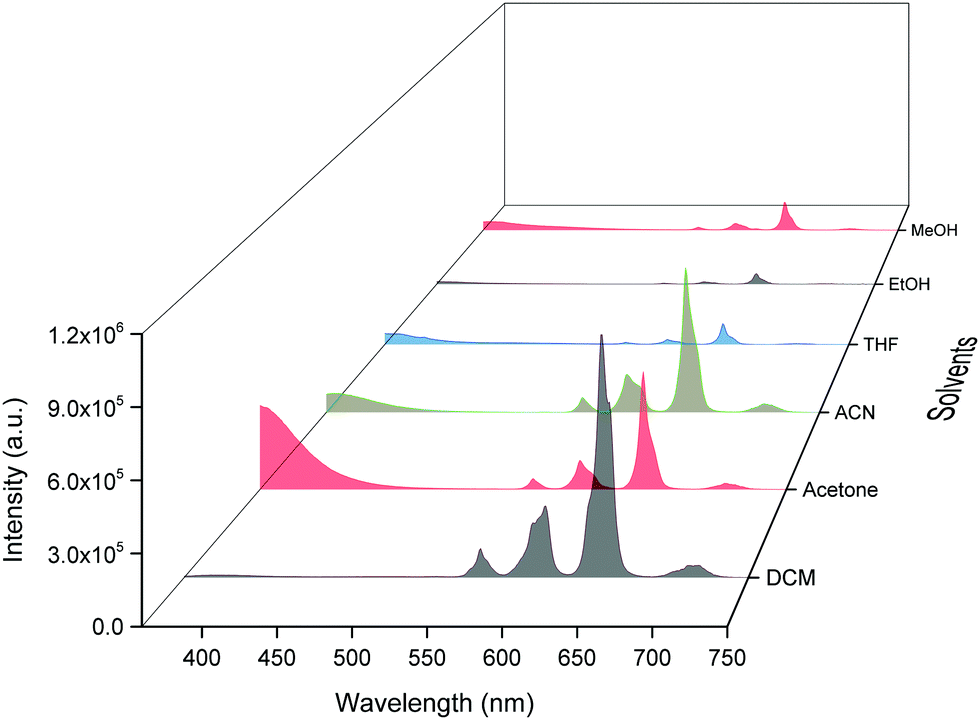
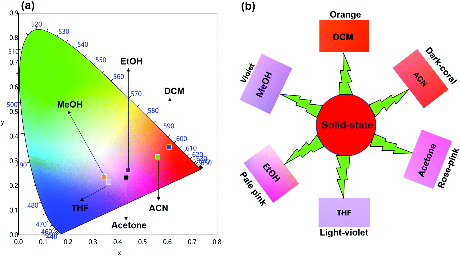
Steady-state emission spectra as shown in Fig. 6 were obtained by exciting them to their λmaxEx and exhibit typical emission transitions of Sm(III) ion as observed and discussed in the case of solid-state. The emission transitions follow the similar trend as observed 4G5/2 → 6H9/2 ≫ 4G5/2 → 6H7/2 > 4G5/2 → 6H5/2 > 4G5/2 → 6H11/2. Moreover, a concomitant residual ligand fluorescence is also observed (Fig. 6 and for a clearer understanding each emission spectrum is separately shown in Fig. S8–S13, ESI†), with their observed color maxima which is absent in the solid-state and increased by changing the solvents. This could be attributed to the interaction of high energy oscillators of solvent(s) and quenching of the 3ππ* energy by the dipole–dipole coupling of the ligands (hfaa and Py-Im) with the solvent32 and thus effecting the overall ET from the ligand(s) to Sm(III) ion. It is well known that the intensity of hypersensitive transition of Ln(III) ions is highly sensitive to the surrounding chemical environment and changes with the change in the solvent. The intensity of the hypersensitive 4G5/2 → 6H9/2 transition in different solvents follows the order: DCM ≫ ACN > Acetone > THF > MeOH > EtOH. The change in the intensity of the ED 4G5/2 → 6H9/2 transition is further reflected in the RSm values 2.75–2.20 on going from DCM to MeOH (Table 1). In order to understand more clearly the effect of different solvents, we determined τexp. in each solvent. In each case decay profiles (Fig. S14–S19, ESI†) satisfactory fit to mono-exponential and data obtained are gathered in Table 1. As expected, τexp. in solution (105.50 ± 0.143 to 14.27 ± 0.033 μs) is shorter than in the solid-state (204.47 ± 4.043 μs). The relatively shorter τexp. value in DCM with almost 50% decrease could be due to: (i) a smaller energy gap of ΔE = 7400 cm−1 between the 4G5/2 and the next lower energy level that matches to the 1st and 2nd overtone of C–H oscillator (νC–H ≈ 2950 cm−1) (ii) quenching of the 3ππ* energy by the dipole–dipole coupling of the ligands (hfaa and Py-Im) with the solvent molecule(s) that decreases the overall ET efficiency and thus leads to RFL in the range between 350–500 nm (Fig. S8–S13, ESI†) and (iii) conversion of the M2L2 assembly into ML structure that diffuses randomly in the solution with free N–H oscillator which results in more efficient quenching in polar solvents. The τexp. further dropped to 20.39 ± 0.041 and 14.27 ± 0.033 μs on changing the solvent to EtOH and MeOH, respectively. This drop in τexp. is due to presence of O–H oscillator (νO–H ≈ 3300–3500 cm−1) that matches the 1st vibrational overtone and thus the Franck–Condon factor becomes more favorable. This results in higher quenching compared to DCM and other solvents and less efficient ET, which could be seen (Fig. 5 and separate emission diagram Fig. S8–S13, ESI†) with concomitant decrease in the intensity of hypersensitive 4G5/2 → 6H9/2 (IRed) in the red region and simultaneous increase in intensity of RFL (IRFL) in the blue region. The change in the IRed and IRFL will subsequently effect the emitted color of the complex. In order to see the emitted color in different solvents, we calculated the CIE color coordinates (x;y) from the emission spectra and the obtained color coordinates are shown in Table 1 and Fig. 7. It is clear from the CIE color diagram that the present complex displays different colors in different solvents such as orange color in DCM and violet in MeOH (Fig. 7b) due to increase of IRFL.
 |
| | Fig. 6 Corrected emission spectra of the complex in different solvents at RT. | |
 |
| | Fig. 7 (a) 1931 CIE Chromaticity diagram and (b) a magnified CIE showing the exact emitted color of the complex in different solvents at RT. | |
The QSmSm of the complex in each solvent was calculated (Table 1) and follows the trend: DCM ≫ ACN > Acetone > THF > EtOH > MeOH, respectively, which is directly related to τexp.. Looking at these interesting PL properties, i.e., remarkably long τexp. in the solid-state and color tunability from orange to violet of the present complex in different solvents, we decided to develop hybrid thin films by encapsulating it in a PU polymer matrix. The encapsulation of lanthanide complex into polymer matrix usually increases the thermal and photostability coupled with the enhanced mechanical strength of the developed hybrid material, a necessary prerequisite for optoelectronic applications.2a,33 The hybrid and flexible thin films were developed by doping different concentrations such as 1%, 2%, 4% and 6% of the complex into the PU polymer matrix assuming that it would give us color-tunable materials. The PL properties of the flexible thin films were analyzed by the steady-state excitation and emission spectra. The excitation spectra of thin films displayed similar broadband as observed in the solid-state and in solution (Fig. S20, ESI†).
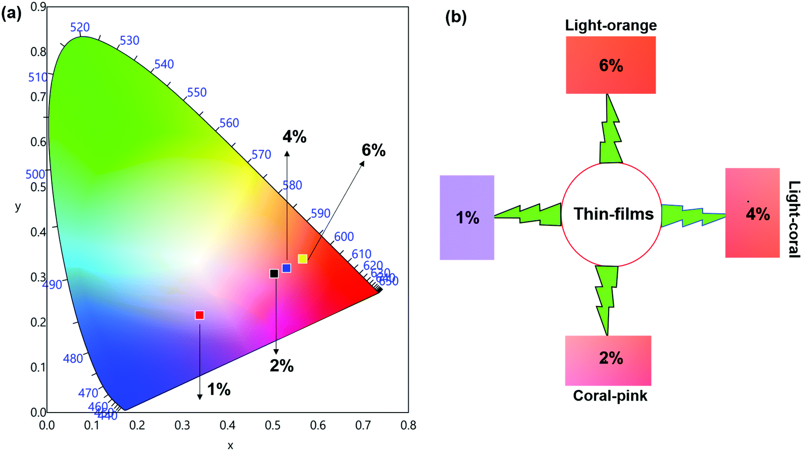
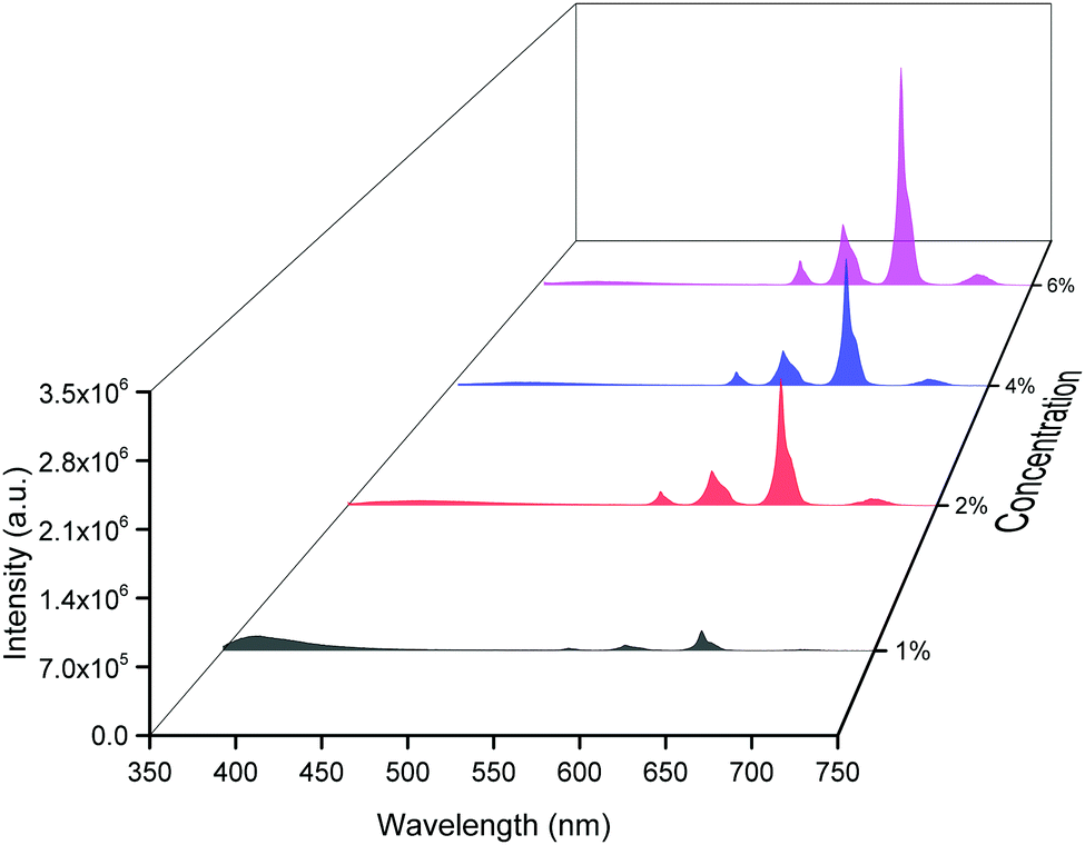
The emission spectra of the hybrid thin films obtained by exciting at λmaxEx displayed typical metal centered emission transitions (discussed above) as observed in the solid-state and in solution as shown in Fig. 8 and the data obtained is shown in Table 2. Hypersensitive 4G5/2 → 6H9/2 emission transition dominates the spectra and is narrower in hybrid thin films with FWHM in 5.66–5.90 nm indicating the higher potential of the developed hybrid thin film for optoelectronic applications. RSm values remain in the range of 1.99–2.45 (Table 2) as observed in different solvents suggesting that incorporation of the complex in the PU polymer matrix does not alter the symmetry and coordination sphere of the bare complex, so it does not lose its structural identity. The τexp. of hybrid thin films were determined as discussed above and the obtained data is gathered in Table 2 while the decay curves together with fitted curves are shown in Fig. S21–S24, ESI.† The lifetime of the hybrid thin films is in the range of 43.55–54.14 μs which is almost 4- and 2-fold shorter than in the solid-state and in DCM solution, this decrease could be attributed to the presence of a high-energy oscillator in the PU polymer matrix, nevertheless it remains at higher end of efficient emitting samarium complexes. To obtain the information for the emitted color by the different hybrid thin films, the CIE color coordinates (Table 2) and diagram were obtained from the steady-state emission spectra and are shown in Fig. 9a and a magnified view of the exact color is also shown in Fig. 9b. As can be seen and as per our assumption from Fig. 9, the developed material displayed color-tunable emission from violet to orange as the doping concentration of the complex was increased from 1–6%. The change in the color from violet to orange is due to the decrease in the IRFL and can be clearly seen in Fig. S25–S28, ESI.†
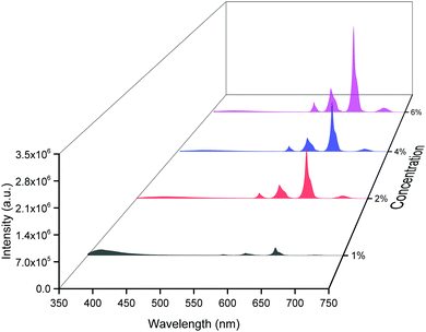 |
| | Fig. 8 Corrected emission spectra of [Sm(hfaa)3(Py-Im)]@PU at different doping concentrations at RT. | |
Table 2 Photophysical parameters of hybrid thin films of [Sm(hfaa)3(Py-Im)] at RT
| Medium (%) |
FWHMa (nm) |
R
Sm
|
τ
exp. (μs) |
CIE (x; y) |
Color |
Q
SmSmc (%) |
FWHM of 4G5/2 → 6H9/2 ED transition.
Ratio of corrected emission intensity of ED to MD transition, i.e.,  . .
 . .
|
| 1 |
5.66 |
1.99 |
43.55 ± 0.274 |
0.3380; 0.2162 |
Violet |
1.40 |
| 2 |
5.90 |
2.45 |
46.85 ± 0.240 |
0.5028; 0.3080 |
Coral pink |
1.51 |
| 4 |
5.72 |
2.40 |
51.81 ± 0.149 |
0.5295; 0.3203 |
Light coral |
1.67 |
| 6 |
5.84 |
2.41 |
54.14 ± 0.131 |
0.5666; 0.3408 |
Light orange |
1.74 |
 |
| | Fig. 9 (a) 1931 CIE Chromaticity diagram and (b) a magnified CIE showing the exact emitted color of [Sm(hfaa)3(Py-Im)]@PU_x% in different doping concentration at RT. | |
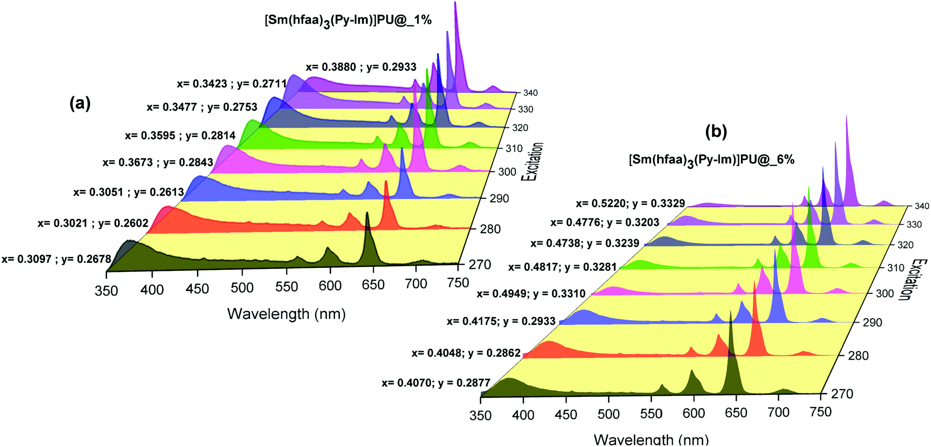
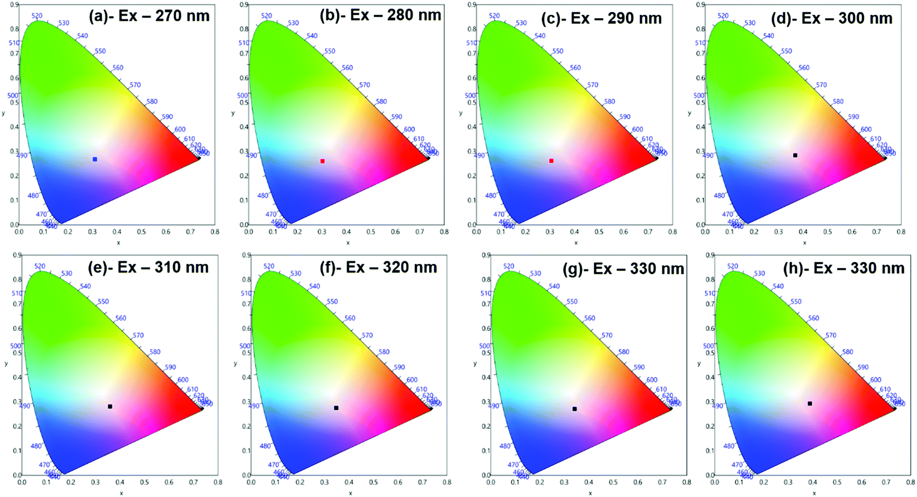
Moreover, to see more color tunability and to increase the chance to get the near-white light or white light emission from the developed hybrid thin films, the excitation wavelength was varied in the range of 270–340 nm at intervals of 10 nm. 1% and 6% doped hybrid materials were taken as reference models, as shown in Fig. 10, the steady-state emission spectra of both thin films exhibit increased emission intensity of the 4G5/2 → 6H9/2 emission transition with IRFL decreasing simultaneously. The corresponding CIE color coordinates is shown in their respective diagram while CIE chromaticity are shown in Fig. 11 and Fig. S29, ESI.† It can be seen from Fig. S29, ESI,† that 6% hybrid thin film displayed orange to light pink. Interestingly, the emission of 1% doped hybrid thin film falls mostly in the white region 1931 CIE chromaticity diagram as can be seen clearly in Fig. 11. On excitation at 300 and 310 nm, the 1% doped hybrid thin film exhibited a near white light emission with CIE coordinates of x = 0.3673; y = 0.2843 and x = 0.3595; y = 0.2814, respectively, which are very close to that for pure white light (x = 0.33, y = 0.33) according to the 1931 CIE diagram. Therefore this material could be a potential candidate to be used as a single-component material to generate white light or near-white light emission for SSL application.34
 |
| | Fig. 10 Corrected emission spectra of hybrid thin films at different excitation wavelengths at RT. The values are CIE (x;y) color coordinates obtained. | |
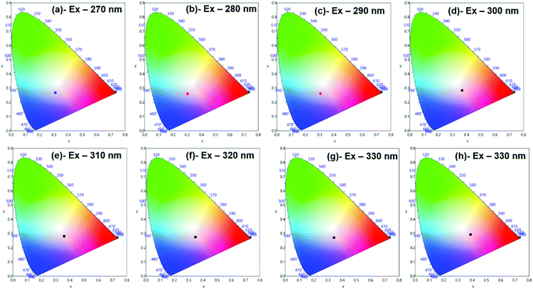 |
| | Fig. 11 1931 CIE Chromaticity diagram of hybrid [Sm(hfaa)3(Py-Im)]@PU_1% thin film at different excitation wavelength displaying near white-light emission. | |
4. Conclusion
We have synthesized a medium-dependent color-tunable Sm(III) complex that dimerizes in the solid-state through N–H⋯O (2.127 Å) and N–H⋯F (2.576 Å) hydrogen bonds. White light emission was achieved by adjustment of doping concentration into a PU polymer and excitation wavelength (as shown in Fig. 10a and 11). ΔE value of ≈7400 cm−1 between the emitting 4G5/2 level and the next lower energy level in the complex results in effective quenching by high energy oscillators and reduces the overall ET efficiency. This leads to RFL in the range between 350–500 nm, which plays a vital role in obtaining white light emission. The present work opens the door to exploit similar color-tunable Sm(III) based white light materials for the fabrication of full-color display devices and SSL applications.
Conflicts of interest
There are no conflicts of interest to declare in this work.
Acknowledgements
MSK acknowledges His Majesty's Trust Fund for Strategic Research (Grant No. SR/SQU/SCI/CHEM/16/02) for funding. RI thanks the HM's Trust Fund for a post-doctoral fellowship. The authors acknowledge the Faculty of Arts and Sciences, Ondokuz Mayıs University, Turkey, for the use of the Stoe IPDS 2 diffractometer (purchased under grant F.279 of the University Research Fund). PRR is grateful to the Engineering and Physical Sciences Research Council (EPSRC) for continued support (Grant EP/K004956/1).
References
-
(a) R. Ilmi, M. S. Khan, Z. Li, L. Zhou, W.-Y. Wong, F. Marken and P. R. Raithby, Inorg. Chem., 2019, 58, 8316–8331 CrossRef CAS PubMed;
(b) Y. He, L. Liu, G. Fu, W. Li, X. Lü, H. He and W.-Y. Wong, J. Mater. Chem. C, 2019, 7, 4800–4807 RSC.
-
(a) R. Ilmi, S. Anjum, A. Haque and M. S. Khan, J. Photochem. Photobiol., A, 2019, 383, 111968 CrossRef;
(b) P. K. Shahi, A. K. Singh, S. K. Singh, S. B. Rai and B. Ullrich, ACS Appl. Mater. Interfaces, 2015, 7, 18231–18239 CrossRef CAS PubMed;
(c) R. Ilmi, S. Kansız, N. Dege and M. S. Khan, J. Photochem. Photobiol., A, 2019, 377, 268–281 CrossRef CAS.
-
(a) R. Cui, W. Liu, L. Zhou, X. Zhao, Y. Jiang, Y. Zheng and H. Zhang, J. Mater. Chem. C, 2017, 5, 2066–2073 RSC;
(b) L. Zhou, L. Li, Y. Jiang, R. Cui, Y. Li, X. Zhao and H. Zhang, ACS Appl. Mater. Interfaces, 2015, 7, 16046–16053 CrossRef CAS PubMed.
-
(a) K. Yanagisawa, Y. Kitagawa, T. Nakanishi, T. Seki, K. Fushimi, H. Ito and Y. Hasegawa, Chem. – Eur. J., 2018, 24, 1956–1961 CrossRef CAS;
(b)
C. D. S. Brites, A. Millán and L. D. Carlos, in Handbook on the Physics and Chemistry of Rare Earths, ed. B. Jean-Claude and K. P. Vitalij, Elsevier, 2016, vol. 49, pp. 339–427 Search PubMed;
(c) D. Errulat, R. Marin, D. A. Gálico, K. L. M. Harriman, A. Pialat, B. Gabidullin, F. Iikawa, O. D. D. Couto, J. O. Moilanen, E. Hemmer, F. A. Sigoli and M. Murugesu, ACS Cent. Sci., 2019, 5, 1187–1198 CrossRef CAS PubMed.
-
(a) J. A. Smith, M. A. Singh-Wilmot, K. P. Carter, C. L. Cahill and J. A. Ridenour, Cryst. Growth Des., 2018, 19, 305–319 CrossRef;
(b) J.-H. Qin, H.-R. Wang, M.-L. Han, X.-H. Chang and L.-F. Ma, Dalton Trans., 2017, 46, 15434–15442 RSC.
- Y. Hasegawa, S.-i. Tsuruoka, T. Yoshida, H. Kawai and T. Kawai, J. Phys. Chem. A, 2008, 112, 803–807 CrossRef CAS PubMed.
-
(a) Y.-H. Zhang, X. Li and S. Song, Chem. Commun., 2013, 49, 10397–10399 RSC;
(b) Q.-Y. Yang, K. Wu, J.-J. Jiang, C.-W. Hsu, M. Pan, J.-M. Lehn and C.-Y. Su, Chem. Commun., 2014, 50, 7702–7704 RSC;
(c) J. Zhang, H. Li, P. Chen, W. Sun, T. Gao and P. Yan, J. Mater. Chem. C, 2015, 3, 1799–1806 RSC;
(d) Y. Xiao, S.-H. Wang, F.-K. Zheng, M.-F. Wu, J. Xu, Z.-F. Liu, J. Chen, R. Li and G.-C. Guo, CrystEngComm, 2016, 18, 721–727 RSC;
(e) J. Leng, H. Li, P. Chen, W. Sun, T. Gao and P. Yan, Dalton Trans., 2014, 43, 12228–12235 RSC.
-
(a) H. Kawai, C. Zhao, S.-I. Tsuruoka, T. Yoshida, Y. Hasegawa and T. Kawai, J. Alloys Compd., 2009, 488, 612–614 CrossRef CAS;
(b) T. Harada, K. Tokuda and K. Nishiyama, J. Mol. Liq., 2014, 200, 77–80 CrossRef CAS;
(c) K. Miyata, T. Nakagawa, R. Kawakami, Y. Kita, K. Sugimoto, T. Nakashima, T. Harada, T. Kawai and Y. Hasegawa, Chem. – Eur. J., 2011, 17, 521–528 CrossRef CAS PubMed.
-
(a) D. Parker and J. A. G. Williams, J. Chem. Soc., Dalton Trans., 1996, 3613–3628, 10.1039/DT9960003613;
(b) Y. Hasegawa, T. Ohkubo, K. Sogabe, Y. Kawamura, Y. Wada, N. Nakashima and S. Yanagida, Angew. Chem., Int. Ed., 2000, 39, 357–360 CrossRef CAS.
- K. Yanagisawa, T. Nakanishi, Y. Kitagawa, T. Seki, T. Akama, M. Kobayashi, T. Taketsugu, H. Ito, K. Fushimi and Y. Hasegawa, Eur. J. Inorg. Chem., 2015, 4769–4774 CrossRef CAS.
-
(a) K. Binnemans, K. Lodewyckx, T. Cardinaels, T. N. Parac-Vogt, C. Bourgogne, D. Guillon and B. Donnio, Eur. J. Inorg. Chem., 2006, 150–157 CrossRef CAS;
(b) T. K. Ronson, H. Adams, L. P. Harding, S. J. A. Pope, D. Sykes, S. Faulkner and M. D. Ward, Dalton Trans., 2007, 1006–1022, 10.1039/B618258E.
- D. B. G. Williams and M. Lawton, J. Org. Chem., 2010, 75, 8351–8354 CrossRef CAS PubMed.
- G. Sheldrick, Acta Crystallogr., Sect. A: Found. Adv., 2015, 71, 3–8 CrossRef PubMed.
- G. Sheldrick, Acta Crystallogr., Sect. C: Struct. Chem., 2015, 71, 3–8 Search PubMed.
- C. F. Macrae, P. R. Edgington, P. McCabe, E. Pidcock, G. P. Shields, R. Taylor, M. Towler and J. van de Streek, J. Appl. Crystallogr., 2006, 39, 453–457 CrossRef CAS.
- A. Spek, J. Appl. Crystallogr., 2003, 36, 7–13 CrossRef CAS.
- L. Farrugia, J. Appl. Crystallogr., 1999, 32, 837–838 CrossRef CAS.
- J. J. McKinnon, D. Jayatilaka and M. A. Spackman, Chem. Commun., 2007, 3814, 10.1039/b704980c.
- M. A. Spackman and D. Jayatilaka, CrystEngComm, 2009, 11, 19–32 RSC.
-
M. J. Turner, J. J. McKinnon, S. K. Wolff, D. J. Grimwood, P. R. Spackman, D. Jayatilaka and M. A. Spackman, CrystalExplorer17, The University of Western Australia, Perth, WA, Australia, 2017 Search PubMed.
-
(a) D. R. van Staveren, G. A. van Albada, J. G. Haasnoot, H. Kooijman, A. M. M. Lanfredi, P. J. Nieuwenhuizen, A. L. Spek, F. Ugozzoli, T. Weyhermüller and J. Reedijk, Inorg. Chim. Acta, 2001, 315, 163–171 CrossRef CAS;
(b) W. J. Evans, D. G. Giarikos, M. A. Johnston, M. A. Greci and J. W. Ziller, J. Chem. Soc., Dalton Trans., 2002, 520–526, 10.1039/B104095M.
-
(a) Y. Oueslati, S. Kansız, A. Valkonen, T. Sahbani, N. Dege and W. Smirani, J. Mol. Struct., 2019, 1196, 499–507 CrossRef CAS;
(b) S. Kansız, A. Tolan, H. İçbudak and N. Dege, J. Mol. Struct., 2019, 1190, 102–115 CrossRef;
(c) W. Guerrab, I.-M. Chung, S. Kansiz, J. T. Mague, N. Dege, J. Taoufik, R. Salghi, I. H. Ali, M. I. Khan, H. Lgaz and Y. Ramli, J. Mol. Struct., 2019, 1197, 369–376 CrossRef CAS.
-
(a) G. Stein and E. Würzberg, J. Chem. Phys., 1975, 62, 208–213 CrossRef CAS;
(b) M. Latva, H. Takalo, V. M. Mukkala, C. Matachescu, J. C. RodriguezUbis and J. Kankare, J. Lumin., 1997, 75, 149–169 CrossRef CAS;
(c) C.-L. Ho, H. Li and W.-Y. Wong, J. Organomet. Chem., 2014, 751, 261–285 CrossRef CAS.
- S. V. Eliseeva, M. Ryazanov, F. Gumy, S. I. Troyanov, L. S. Lepnev, J.-C. G. Bünzli and N. P. Kuzmina, Eur. J. Inorg. Chem., 2006, 4809–4820 CrossRef CAS.
- Y. Zheng, L. Fu, Y. Zhou, J. Yu, Y. Yu, S. Wang and H. Zhang, J. Mater. Chem., 2002, 12, 919–923 RSC.
- M. D. Regulacio, M. H. Pablico, J. A. Vasquez, P. N. Myers, S. Gentry, M. Prushan, S.-W. Tam-Chang and S. L. Stoll, Inorg. Chem., 2008, 47, 1512–1523 CrossRef CAS PubMed.
- R. Ilmi and K. Iftikhar, Polyhedron, 2017, 127, 191–202 CrossRef CAS.
- J. Shi, Y. Hou, W. Chu, X. Shi, H. Gu, B. Wang and Z. Sun, Inorg. Chem., 2013, 52, 5013–5022 CrossRef CAS PubMed.
- Z. Li, J. Yu, L. Zhou, H. Zhang and R. Deng, Inorg. Chem. Commun., 2008, 11, 1284–1287 CrossRef CAS.
- W. T. Carnall, P. R. Fields and K. Rajnak, J. Chem. Phys., 1968, 49, 4424–4442 CrossRef CAS.
- A. Døssing, Eur. J. Inorg. Chem., 2005, 1425–1434 CrossRef.
- W.-S. Lo, J. Zhang, W.-T. Wong and G.-L. Law, Inorg. Chem., 2015, 54, 3725–3727 CrossRef CAS PubMed.
- K. Binnemans, Chem. Rev., 2009, 109, 4283–4374 CrossRef CAS PubMed.
-
(a) R. Ilmi, M. S. Khan, W. Sun, L. Zhou, W.-Y. R. Wong and P. R. Raithby, J. Mater. Chem. C, 2019, 7, 13966–13975 RSC;
(b) L. Ying, C.-L. Ho, H. Wu, Y. Cao and W.-Y. Wong, Adv. Mater., 2014, 26, 2459–2473 CrossRef CAS PubMed;
(c) X. Yang, G. Zhou and W.-Y. Wong, J. Mater. Chem. C, 2014, 2, 1760–1778 RSC;
(d) G. Zhou, W.-Y. Wong and S. Suo, J. Photochem. Photobiol., C, 2010, 11, 133–156 CrossRef CAS.
Footnote |
| † Electronic supplementary information (ESI) available. CCDC 1943973. For ESI and crystallographic data in CIF or other electronic format see DOI: 10.1039/c9nj06287d |
|
| This journal is © The Royal Society of Chemistry and the Centre National de la Recherche Scientifique 2020 |
Click here to see how this site uses Cookies. View our privacy policy here. 
 Open Access Article
 This Open Access Article is licensed under a
  *a,
Sevgi
Kansız
*a,
Sevgi
Kansız
 .
c
.
c
 .
.
 .
c
.
c
 .
.