A highly selective and active metal-free catalyst for ammonia production†
Chengyu
Xing
a,
Chenyu
Wu
 a,
Yurui
Xue
*bc,
Yingjie
Zhao
 *a,
Lan
Hui
b,
Huidi
Yu
b,
Yuxin
Liu
b,
Qingyan
Pan
a,
Yan
Fang
b,
Chao
Zhang
b,
Danyan
Zhang
b,
Xi
Chen
b and
Yuliang
Li
 *bd
*bd
aCollege of Polymer Science and Engineering, Qingdao University of Science and Technology, Qingdao 266042, P. R. China. E-mail: yz@qust.edu.cn
bInstitute of Chemistry Chinese Academy of Sciences, Beijing, 100190, P. R. China. E-mail: ylli@iccas.ac.cn; xueyurui@iccas.ac.cn
cScience Center for Material Creation and Energy Conversion, School of Chemistry and Chemical Engineering, Shandong University, Jinan 250100, P. R. China
dUniversity of Chinese Academy of Sciences, Beijing 100049, P. R. China
First published on 10th July 2020
Abstract
We report a facile surface-induced method for the in situ growth of single-/few-layered crystalline fluorographdiyne film on the surface of carbon fibers (cFGDY). The crystallized structure of cFGDY was directly confirmed by the scanning/transmission electron microscopy (SEM/TEM), high-resolution TEM (HRTEM) and computer simulation, selected area electron diffraction (SAED), X-ray photoelectron spectroscopy (XPS), and Raman spectroscopy. cFGDY showed a 9-fold stacking mode. Our results show that cFGDY is a metal-free electrocatalyst with unique structure and excellent performance for ammonia production from nitrogen and water efficiently at room temperature and ambient pressure, achieving a high NH3 production rate and Faraday efficiency in neutral conditions. This work provides an efficient catalyst system with determined chemical and electronic structures for highly selective and active nitrogen reduction, serving as a promising platform towards the development of novel metal-free catalysts.
New conceptsWe report a new 3D metal-free nitrogen reduction reaction (NRR) electrocatalyst based on crystalline fluorographdiyne film grown on the surface of carbon fibers (cFGDY). By combining theoretical and experimental studies, we have comprehensively investigated the stacking mode for the carbon based 2D material and demonstrated a 9-fold stacking mode of the cFGDY. cFGDY shows determined electronic and chemical structures, determined active sites, and clear reaction mechanism and process. These advantages of cFGDY endow it with excellent performance for ammonia production from nitrogen and water at room temperature and ambient pressure, achieving high NH3 production rate and Faraday efficiency in neutral conditions. The fundamental study related NH3 production opens up a new avenue to efficient catalyst systems for highly selective and active nitrogen reduction, serving as a promising platform towards the development of novel metal-free catalysts. |
Introduction
Ammonia (NH3) production from atmospheric nitrogen has attracted increasing attention and been regarded as a promising way for sustainable energy solutions. Currently, the industrial NH3 production mainly relies on an energy-consuming Haber–Bosch process, which requires high temperature (>300 °C) and high pressure (>100 atm).1–3 Electro-catalyzed N2 reduction reaction (NRR) offers an ideal way for ammonia production from N2 and water at room temperatures and ambient pressures.4–7 Many efforts have recently been devoted to develop electrocatalysts that are capable of catalyzing NRR processes. Although metal-based catalysts have shown NRR catalytic activity, the corrosion remains a big challenge.8–11 Metal-free catalysts, such as heteroatom-doped carbon,12 polymeric carbon nitride,13 B4C nanosheets,14 and black P,15 have aroused great attention. However, the NH3 production rate of the reported electrocatalyst are still too low and far from practical applications.Graphdiyne (GDY), the first sp + sp2 cohybridized two dimensional carbon allotrope, has shown unique properties and excellent performances in many fields (such as catalysis, and energy conversion and storage).16–24 Controllable heteroatom substitution without changing the skeleton of the material is an effective strategy to tune the electronic/chemical structure and improve the catalytic properties. Yang and coworkers25 reported that crystalline carbon could improve the electron mobility and thus enhance corresponding electrocatalytic activities. Therefore, we would like to synthesize crystalline single-/few-layer FGDY. Here, we developed a surface-induced method for the synthesis of crystalline fluorographdiyne films on the surface of carbon fibres (cFGDY) using 1,3,5-triethynyl-2,4,6-trifluorobenzene (TETFB) as precursor. Experimental results confirmed the crystalline nature of cFGDY. The obtained cFGDY could be directly used as a self-supported metal-free electrode for NH3 synthesis. The unique structures of cFGDY endow it with 100% selectivity, high activity and stability for NRR.
Results and discussion
Fig. S1 (ESI†) shows the schematic illustration of the growing strategy of the crystalline FGDY (please see the Method section for details). Briefly, the freshly-cleaned 3-dimension weaved carbon fibres (CF) with smooth surface were directly used as substrates and added into a mixed solution of pyridine![[thin space (1/6-em)]](https://www.rsc.org/images/entities/char_2009.gif) :
:![[thin space (1/6-em)]](https://www.rsc.org/images/entities/char_2009.gif) acetone
acetone![[thin space (1/6-em)]](https://www.rsc.org/images/entities/char_2009.gif) :
:![[thin space (1/6-em)]](https://www.rsc.org/images/entities/char_2009.gif) N,N,N′,N′-tetramethylethylenediamine (volume ratio = 5
N,N,N′,N′-tetramethylethylenediamine (volume ratio = 5![[thin space (1/6-em)]](https://www.rsc.org/images/entities/char_2009.gif) :
:![[thin space (1/6-em)]](https://www.rsc.org/images/entities/char_2009.gif) 50
50![[thin space (1/6-em)]](https://www.rsc.org/images/entities/char_2009.gif) :
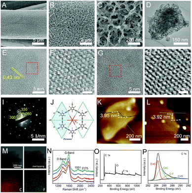
:![[thin space (1/6-em)]](https://www.rsc.org/images/entities/char_2009.gif) 1) containing pieces of copper foils. To control the coupling reaction kinetics, a low concentration of TETFB was employed for the growth of cFGDY. After a 12 hour reaction at 50 °C, colour of the substrate changed from grey to black (Fig. S2, ESI†), indicating the formation of cFGDY. Scanning electron microscopy (SEM, Fig. 1A–C) and transmission electron microscopy (TEM, Fig. 1D) images revealed the cFGDY possesses a porous 3D morphology that benefits to maximize the number of active sites. The contact angle test shows that pure CF has a hydrophobic surface with a contact angle of 130.5 (Fig. S3a, ESI†) and cFGDY has a superhydrophilic surface (contact angle is 0°, Fig. S3b, ESI†), indicating that the fluorination could produce a more hydrophilic surfaces which can consequently make the interaction between the active sites and electrolytes more easily and thus improving the catalytic performances.26
1) containing pieces of copper foils. To control the coupling reaction kinetics, a low concentration of TETFB was employed for the growth of cFGDY. After a 12 hour reaction at 50 °C, colour of the substrate changed from grey to black (Fig. S2, ESI†), indicating the formation of cFGDY. Scanning electron microscopy (SEM, Fig. 1A–C) and transmission electron microscopy (TEM, Fig. 1D) images revealed the cFGDY possesses a porous 3D morphology that benefits to maximize the number of active sites. The contact angle test shows that pure CF has a hydrophobic surface with a contact angle of 130.5 (Fig. S3a, ESI†) and cFGDY has a superhydrophilic surface (contact angle is 0°, Fig. S3b, ESI†), indicating that the fluorination could produce a more hydrophilic surfaces which can consequently make the interaction between the active sites and electrolytes more easily and thus improving the catalytic performances.26
High-resolution TEM (HRTEM) images (Fig. 1E–H) and selected area electron diffraction (SAED) patterns (Fig. 1I) reveal the high crystallinity nature of cFGDY. The SAED pattern of cFGDY from the normal direction of its 2D plane clearly reflects a reciprocal lattice complying with the D6h point group and the P6/mmm space group of the expected FGDY structure of a single layer (Fig. 1J and Fig. S6, ESI†). The representative atomic force microscopy (AFM) images of cFGDY nanosheets are shown in Fig. 1K and L. It is observed that the cFGDY nanosheet shows a height of around 3.92 (3.95) nm, in accordance with the theoretical thickness of the 9-fold stacking structure which will be detailedly discussed below. Raman spectrum of cFGDY (Fig. 1N) shows four characteristic peaks at 1369 (D band), 1579 (G band), 1931 and 2175 cm−1 (–C![[triple bond, length as m-dash]](https://www.rsc.org/images/entities/char_e002.gif) C–), respectively. Raman analysis clearly shows the intensity of the D band of cFGDY is lower than G band, indicating a high structure regularity of cFGDY.27,28 Energy disperse spectrum (EDS) analysis (Fig. 1M) together with the X-ray photoelectron spectroscopy (XPS) spectrum showed that the FGDY consists only of C and F elements (Fig. 1O). The high-resolution C 1s XPS spectrum (Fig. 1P) can be deconvoluted into four sub-peaks at 284.42 (sp2-C), 285.2 (sp-C), 286.8 (C–F), and 288.8 eV (C
C–), respectively. Raman analysis clearly shows the intensity of the D band of cFGDY is lower than G band, indicating a high structure regularity of cFGDY.27,28 Energy disperse spectrum (EDS) analysis (Fig. 1M) together with the X-ray photoelectron spectroscopy (XPS) spectrum showed that the FGDY consists only of C and F elements (Fig. 1O). The high-resolution C 1s XPS spectrum (Fig. 1P) can be deconvoluted into four sub-peaks at 284.42 (sp2-C), 285.2 (sp-C), 286.8 (C–F), and 288.8 eV (C![[double bond, length as m-dash]](https://www.rsc.org/images/entities/char_e001.gif) O), respectively. The peak area ratio of sp2-C to sp-C is 1, in accordance with the FGDY model. The small amounts of O peak is due to the oxygen adsorption from the air, which can also be observed from other carbon materials.29 The peak at 687.65 eV corresponds to the highly polarized C–F bond (Fig. S4, ESI†), which would be responsible for the improvement of the catalytic performance. These results indicated the successful synthesis of cFGDY.
O), respectively. The peak area ratio of sp2-C to sp-C is 1, in accordance with the FGDY model. The small amounts of O peak is due to the oxygen adsorption from the air, which can also be observed from other carbon materials.29 The peak at 687.65 eV corresponds to the highly polarized C–F bond (Fig. S4, ESI†), which would be responsible for the improvement of the catalytic performance. These results indicated the successful synthesis of cFGDY.
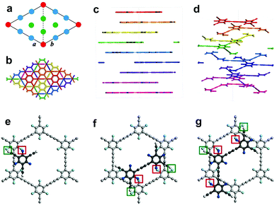
Comparison of the simulated structure with the average plane spacing (d) corresponding to the closest diffraction point (dmax = 0.467 nm, with respect to the central transmission spot), we were able to confirm a 9-fold stacking structure with a set of highest-atom-density planes (Fig. 2a–d, Fig. S5, S6 and Table S1, ESI,†dmax,calc = 0.472 nm, corresponding to d of the highest-density {300} planes, i.e. d{300}) is highly consistent with that determined from experimental SAED pattern (Fig. 1K; dmax, SAED = 0.467 nm; relative error δ as low as 1.1%). Acknowledging 9-fold stacking of the synthesized cFGDY, we were extremely curious about the driving force and the reason behind this preference for 9-fold stacking over other stacking modes (Fig. S6, ESI†). It was found by DFT calculations that the F atoms in formed cFGDY layer and H atoms of unreacted acetylenic groups could form F–H hydrogen bonds, which directing or templating the formation of 9-fold stacking and keeping the 9-fold stacking mode all along (Fig. 2e–g and Fig. S7, ESI†). According to the HRTEM results (Fig. 1E, G, and I), the FGDY exhibited the lattice distance of 0.437 nm, corresponding to {300} planes.
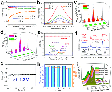
We subsequently assessed the performances of electrocatalyzed nitrogen reduction reaction (NRR) based on the crystalline FGDY electrode. All experiments were performed in three-electrode configuration with two chambers separated by Nafion membranes at room temperatures and ambient pressures in 0.1 M Na2SO4 aqueous solutions. Prior to each experiments, the electrolytes were saturated with N2 and were continuously bubbled with N2 during the NRR processes. cFGDY exhibits good stability at different potentials (Fig. 3a) and the highest NH3 yield rate (YNH3) of 44.14 ± 4.54 μg h−1 mgcat−1 at −1.2 V versus SCE (Fig. 3b and c and Fig. S8 and S9, ESI†). This value is much higher than reported metal-free electrocatalysts (Tables S2 and S3, ESI†) such as fluorographene nanosheet (9.3 μg h−1 mgcat−1),4 O-CNT (32.33 μg h−1 mgcat−1),30 and even higher than metal-based ones such as b-FeOOH nanorods (23.32 μg h−1 mgcat−1),31 MIL-125(Ti) (14.8 μg h−1 mgcat−1),32 and Pd/C (4.5 μg h−1 mgcat−1).33 It also shows the largest Faraday Efficiency (FE) of 25.95 ± 2.6% at −1.2 V versus SCE among the reported metal-free electrocatalysts (Fig. 3d and e and Tables S2 and S3, ESI†). To confirm the origin of the NH3, a series of control experiments were performed. Pure CF exhibited very poor NRR performance (YNH3 = 0.2 μg h−1 mgcat−1, FE = 0.1%) in N2-saturated 0.1 M Na2SO4 (Fig. S10 and S11, ESI†); for cFGDY, in Ar-saturated 0.1 M Na2SO4, no NH3 could be detected (Fig. 3c and d); 15N-isotopic labelling experiments were carried out to confirm the N source of the produced NH3.34 As shown in Fig. 3f, the 1H NMR spectra of the standard sample exhibits a triplet integral and a doublet integral, which correspond to 14NH4+ and 15NH4+ respectively. By using 15N2 as the feeding gas, only 15NH4+ was observed (red line in Fig. 3f). While, only 14NH4+ could be observed (black line in Fig. 3f) when the 14N2 was used as the feeding gas. 15N isotope-labelling experiments over cFGDY solidly confirm the N elements in the produced NH3 originated from the N2. Besides, no N2H4 could be detected over the whole NRR process (Fig. S12, ESI†). These results clearly demonstrate the formation of NH3 from N2 reduction, indicating the 100% reaction selectivity of cFGDY.
Stability is another important criterion for practical uses of an electrocatalyst. As shown in Fig. 3g, under the continuous N2 gas flow, cFGDY could maintain the nitrogen reduction activity over 17.5 h at a potential of −1.2 V versus SCE with negligible decrease in the current density. Besides, the NH3 production rate and FE for the NRR process over cFGDY exhibits slight variation after the 5-cycle tests (appropriate 90% retention at −1.2 V; Fig. 3h). Notably, the SEM (Fig. S13, ESI†), XPS (Fig. S14 and S15, ESI†) and Raman (Fig. 3i) results of the cFGDY showed negligible variation after the long-term NRR, indicating the excellent stability of the cFGDY. No N2H4 has been detected during the NRR process, indicating the 100% NRR selectivity of cFGDY.
Electrochemical impedance spectroscopy (EIS) was measured to study the catalytic kinetics of the catalysts (Fig. S16, ESI†). The cFGDY shows a smaller solution resistance (R1 = 28.45 Ω) and charge transfer resistance (R2 = 2.334 Ω) than pure CF (R1 = 35.97 Ω, R2 = 351.1 Ω), verifying the high conductivity of cFGDY. The EIS after NRR was also measured. A slight in-crease in both R1 (29.83 Ω) and R2 (28.31 Ω) was observed. In addition, the electrochemically active surface area (ECSA) was evaluated by measuring the double-layer capacitances (Cdl, Fig. S17, ESI†). cFGDY shows a Cdl of 5.0 mF cm−2, about 50 times larger than pure CF (0.1 mF cm−2), revealing the large numbers of the active sites of the cFGDY that benefits to the improvement of the reaction activity.
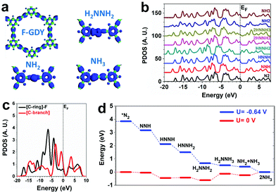
DFT calculations are applied to investigate the NRR on cFGDY from both electronic and energetic perspective. The calculation models of cFGDY with the similar features to previous studies was employed (Fig. S18, ESI†).35 Compared with the F-connected C-ring sites, the C-branch site are more electron-rich, indicating the electroactive sites. For the adsorption of key intermediates, the electrons are evidentially localized near the C-branch region, confirming their electroactivity feature (Fig. 4a). By analyzing the projected density of states (PDOS) of the valence band (VB) with different adsorbates, it is noted that the valence bands are highly stabilized during the NRR with nearly unchanged VB bands. This feature leads to the robustness of the electrocatalyst with high stability during the NRR. However, the band offset of VB is noted (Fig. 4b). The detailed comparison between different C sites determines the preferred reaction pathway. Compared to the F-connected C-ring sites, the C-branch sites show a higher position that is closer to the EF, supporting a higher electroactivity of NRR (Fig. 4c). Thus, a determined pathway has been investigated from the energetic view. The NRR shows a continuous downhill until the formation of *NH2NH3 with 0.49 eV energy barrier. The final formation of NH3 also shows a barrier of 0.24 eV. By applying U = −0.64 V potential, the NRR process becomes a purely downhill trend with an overall energy gain of −3.85 eV (Fig. 4d).
Conclusions
We successfully synthesized crystalline FGDY with a 9-fold stacking mode as determined by the HRTEM, XRD and DFT analysis. The high-quality and unique properties of the cFGDY makes it can function as an efficient metal-free NRR electrocatalysts NRR. DFT calculations support that the alkynic C-branch are active sites, which is beneficial for the adsorption of key intermediates, N![[triple bond, length as m-dash]](https://www.rsc.org/images/entities/char_e002.gif) N activation, and can facilitate electron transfer of the subsequent N2-to-NH3 hydrogenation process. This work not only paves a new way for the facile synthesis of highly selective and active metal-free catalysts with determined chemical/electronic structure, but also provides a model for more accurate understanding of the nitrogen production on carbon materials.
N activation, and can facilitate electron transfer of the subsequent N2-to-NH3 hydrogenation process. This work not only paves a new way for the facile synthesis of highly selective and active metal-free catalysts with determined chemical/electronic structure, but also provides a model for more accurate understanding of the nitrogen production on carbon materials.
Conflicts of interest
There are no conflicts to declare.Acknowledgements
This work was supported by the National Nature Science Foundation of China (21790050 and 21790051), the National Key Research and Development Project of China (2016YFA0200104 and 2018YFA0703501), and the Key Program of the Chinese Academy of Sciences (QYZDY-SSW-SLH015).Notes and references
- R. Schlogl, Angew. Chem., Int. Ed., 2003, 42, 2004–2008 CrossRef PubMed.
- H. Liu, Chin. J. Catal., 2014, 35, 1619–1640 CrossRef CAS.
- T. Kandemir, M. E. Schuster, A. Senyshyn, M. Behrens and R. Schlçgl, Angew. Chem., Int. Ed., 2013, 52, 12723–12726 CrossRef CAS PubMed.
- X. Cui, C. Tang and Q. Zhang, Adv. Energy Mater., 2018, 8, 1800369 CrossRef.
- C. Guo, J. Ran, A. Vasileff and S. Qiao, Energy Environ. Sci., 2018, 11, 45–56 RSC.
- Z. H. Xue, S. N. Zhang, Y. X. Lin, H. Su, G. Y. Zhai, J. T. Han, Q. Y. Yu, X. H. Li, M. Antonietti and J. S. Chen, J. Am. Chem. Soc., 2019, 141(38), 14976–14980 CrossRef CAS PubMed.
- Y. X. Lin, S. N. Zhang, Z. H. Xue, J. J. Zhang, H. Su, T. J. Zhao, G. Y. Zhai, X. H. Li, M. Antonietti and J. S. Chen, Nat. Commun., 2019, 10, 4830 CrossRef PubMed.
- L. Zhang, X. Ji, X. Ren, Y. Ma, X. Shi, Z. Tian, A. M. Asiri, L. Chen, B. Tang and X. Sun, Adv. Mater., 2018, 30, 1800191 CrossRef PubMed.
- Y. Hao, Y. Guo, L. Chen, M. Shu, X. Wang, T. Bu, W. Gao, N. Zhang, X. Su, X. Feng, J. Zhou, B. Wang, C. Hu, A. Yin, R. Si, Y. Zhang and C. Yan, Nat. Catal., 2019, 2, 448–456 CrossRef CAS.
- R. Paul, F. Du, L. Dai, Y. Ding, Z. Wang, F. Wei and A. Roy, Adv. Mater., 2019, 14, 1805598 CrossRef PubMed.
- D. Deng, K. Novoselov, Q. Fu, N. Zheng, Z. Tian and X. Bao, Nat. Nanotechnol., 2016, 11, 218–230 CrossRef CAS PubMed.
- J. Zhao, J. Yang, L. Ji, H. Wang, H. Chen, Z. Niu, Q. Liu, T. Li, G. Cui and X. Sun, Chem. Commun., 2019, 55, 4266–4269 RSC.
- C. Lv, Y. Qian, C. Yan, Y. Ding, Y. Liu, G. Chen and G. Yu, Angew. Chem., Int. Ed., 2018, 57, 10246–10250 CrossRef CAS PubMed.
- W. Qiu, X. Xie, J. Qiu, W. Fang, R. Liang, X. Ren, X. Ji, G. Cui, A. M. Asiri, G. Cui, B. Tang and X. Sun, Nat. Commun., 2018, 9, 3485 CrossRef PubMed.
- L. Zhang, L. Ding, G. Chen, X. Yang and H. Wang, Angew. Chem., Int. Ed., 2019, 58, 2612–2616 CrossRef CAS PubMed.
- G. Li, Y. Li, H. Liu, Y. Guo, Y. Li and D. Zhu, Chem. Commun., 2010, 46, 3256 RSC.
- C. Huang, Y. Li, N. Wang, Y. Xue, Z. Zuo, H. Liu and Y. Li, Chem. Rev., 2018, 118, 7744–7803 CrossRef CAS PubMed.
- X. Gao, H. Liu and D. Wang, J. Chem. Soc. Rev., 2019, 48, 908 RSC.
- R. Sakamoto, N. Fukui, H. Maeda, R. Matsuoka, R. Toyoda and H. Nishihara, Adv. Mater., 2019, 31, 1804211 CrossRef CAS PubMed.
- L. Hui, Y. Xue, H. Yu, Y. Liu, Y. Fang, C. Xing, B. Huang and Y. Li, J. Am. Chem. Soc., 2019, 141, 10677–10683 CrossRef CAS PubMed.
- Y. Xue, B. Huang, Y. Yi, Y. Guo, Z. Zuo, Y. Li, Z. Jia, H. Liu and Y. Li, Nat. Commun., 2018, 9, 1460 CrossRef PubMed.
- H. Yu, Y. Xue, L. Hui, C. Zhang, Y. Li, Z. Zuo, Y. Zhao, Z. Li and Y. Li, Adv. Mater., 2018, 30, 1707082 CrossRef PubMed.
- J. Li, J. Xu, Z. Xie, X. Gao, J. Zhou, Y. Xiong, C. Chen, J. Zhang and Z. Liu, Adv. Mater., 2018, 30, 1800548 CrossRef PubMed.
- N. Wang, J. He, K. Wang, Y. Zhao, T. Jiu, C. Huang and Y. Li, Adv. Mater., 2019, 31, 1803202 CrossRef CAS PubMed.
- W. Niu, K. Marcus, L. Zhou, Z. Li, L. Shi, K. Liang and Y. Yang, ACS Catal., 2018, 8, 1926–1931 CrossRef CAS.
- S. Lin, L. Xu, A. Wang and Z. Wang, Nat. Commun., 2020, 11, 399 CrossRef CAS PubMed.
- Y. Jia, L. Zhang, A. Du, G. Gao, J. Chen, X. Yan, C. L. Brown and X. Yao, Adv. Mater., 2016, 28, 9532–9538 CrossRef CAS PubMed.
- Y. Jia, L. Zhang, L. Zhuang, H. Liu, X. Yan, X. Wang, J. Liu, J. Wang, Y. Zheng, Z. Xiao, E. Taran, J. Chen, D. Yang, Z. Zhu, S. Wang, L. Dai and X. Yao, Nat. Catal., 2019, 2, 688–695 CrossRef CAS.
- M. Ryota, S. Ryota, H. Ken, S. Sono, M. Hiroyasu, N. Kosuke and N. Hiroshi, J. Am. Chem. Soc., 2017, 139, 3145–3152 CrossRef PubMed.
- J. Zhao, B. Wang, Q. Zhou, H. Wang, X. Li, H. Chen, Q. Wei, D. Wu, Y. Luo, J. You, F. Gong and X. Sun, Chem. Commun., 2019, 55, 4997–5000 RSC.
- X. Zhu, Z. Liu, Q. Liu, Y. Luo, X. Shi, A. M. Asiri, Y. Wu and X. Sun, Chem. Commun., 2018, 54, 11332–11335 RSC.
- Q. Qin, Y. Zhao, M. Schmallegger, T. Heil, J. Schmidt, R. Walczak, G. Gescheidt-Demner, H. Jiao and M. Oschatz, Angew. Chem., Int. Ed., 2019, 58, 13101–13106 CrossRef CAS PubMed.
- J. Wang, L. Yu, L. Hu, G. Chen, H. Xin and X. Feng, Nat. Commun., 2018, 9, 1795 CrossRef PubMed.
- H. Zou, W. Rong, B. Long, Y. Ji and L. Duan, ACS Catal., 2019, 9, 10649–10655 CrossRef CAS.
- Z. Feng, Y. Li, Y. Tang, W. Chen, R. Li, Y. Ma and X. Dai, J. Mater. Sci., 2020, 55, 8220–8230 CrossRef CAS.
Footnote |
| † Electronic supplementary information (ESI) available. See DOI: 10.1039/d0nh00287a |
| This journal is © The Royal Society of Chemistry 2020 |


